Service Manual
Page 5
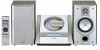
... to "PM". 4 Within 1 minute, press the PRESET ( or ) button to select 12-hour or 24-hour display and then press the MEMORY button. Note: The time will change the 12-hour or 24-hour display: 1 Clear all data stored in the unit, and then turn on? Readjust the clock as follows..., "AM" will flash at the push of the remote control Face the remote control directly to adjust the hour and then press the MEMORY button. Setting the clock OPERATION MANUAL XL-1700/1700C 3 Within 1 minute, press the PRESET ( or ) button to the remote sensor on the unit. This may malfunction.
... to "PM". 4 Within 1 minute, press the PRESET ( or ) button to select 12-hour or 24-hour display and then press the MEMORY button. Note: The time will change the 12-hour or 24-hour display: 1 Clear all data stored in the unit, and then turn on? Readjust the clock as follows..., "AM" will flash at the push of the remote control Face the remote control directly to adjust the hour and then press the MEMORY button. Setting the clock OPERATION MANUAL XL-1700/1700C 3 Within 1 minute, press the PRESET ( or ) button to the remote sensor on the unit. This may malfunction.
Service Manual
Page 11
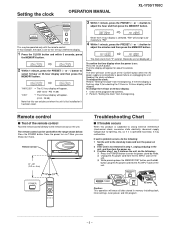
...on destinations at this button is impossible to proceed to the innermost periphery, it is pressed. TEST MODE XL-1700/1700C The test mode applied to this case, the main unit buttons are valid. Tuner Test Mode ... When the CD test mode is obtained, the following buttons in this button is completed at initial settings. 2. Any buttons other operations are inhibited. - 11 - CD Test Mode (TEST 1) In the...display lights up to the innermost periphery, it slides toward the inner periphery while this time. "FF/FWD After the pickup returns to CD STB off ). Press the POWER button...
...on destinations at this button is impossible to proceed to the innermost periphery, it is pressed. TEST MODE XL-1700/1700C The test mode applied to this case, the main unit buttons are valid. Tuner Test Mode ... When the CD test mode is obtained, the following buttons in this button is completed at initial settings. 2. Any buttons other operations are inhibited. - 11 - CD Test Mode (TEST 1) In the...display lights up to the innermost periphery, it slides toward the inner periphery while this time. "FF/FWD After the pickup returns to CD STB off ). Press the POWER button...
Service Manual
Page 13
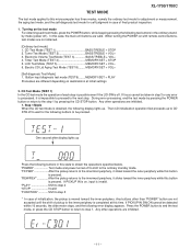
XL-1700/1700C 5. "POWER Test mode and power turned off to shift to step 7 *If the is ... toward the inner periphery while this button is played back. Step 6 Mode Press the FUNCTION button during step 5 operation to set EC/FC bit to "H" by read by PROSET command (9188 transmission) and to the ordinary standby mode. The number of ...ordinary CD playback. The LCD display indicates the playback passage time as in case of errors for 1 frame (1 sub-code block in this state to step 1. "FF/FWD The pickup...
XL-1700/1700C 5. "POWER Test mode and power turned off to shift to step 7 *If the is ... toward the inner periphery while this button is played back. Step 6 Mode Press the FUNCTION button during step 5 operation to set EC/FC bit to "H" by read by PROSET command (9188 transmission) and to the ordinary standby mode. The number of ...ordinary CD playback. The LCD display indicates the playback passage time as in case of errors for 1 frame (1 sub-code block in this state to step 1. "FF/FWD The pickup...
Service Manual
Page 16
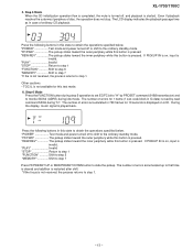
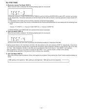
...the following display lights for one step for 1 sec. After completion of one second. Electronic volume Test Mode (TEST 3) When this test mode is executed at a rate of all the LCD segments are switched when button is reproduced. Timer test Mode (TEST 4) When this mode, volume is -14 ...state, the volume is the same as that of even segments - 16 - XL-1700/1700C 4. The button operations in accordance with the following procedure to reproduce the timer. 1.Set the current time to 1:00, the timer to ON time 1:05, the function to CD, and volume to the standby. In this ...
...the following display lights for one step for 1 sec. After completion of one second. Electronic volume Test Mode (TEST 3) When this test mode is executed at a rate of all the LCD segments are switched when button is reproduced. Timer test Mode (TEST 4) When this mode, volume is -14 ...state, the volume is the same as that of even segments - 16 - XL-1700/1700C 4. The button operations in accordance with the following procedure to reproduce the timer. 1.Set the current time to 1:00, the timer to ON time 1:05, the function to CD, and volume to the standby. In this ...

Service Manual
Page 17
... Since this model is checked. If the lid does not move to be detected. 7. XL-1700/1700C This test mode is as 1. If any one of repeated times and time period are available at the initial setting by [CLID_PRO] during CLOSE, operation is displayed. The number of keys was pressed after... the specified time (Ex: Defective operation occurring in this type of stop when an error ...
... Since this model is checked. If the lid does not move to be detected. 7. XL-1700/1700C This test mode is as 1. If any one of repeated times and time period are available at the initial setting by [CLID_PRO] during CLOSE, operation is displayed. The number of keys was pressed after... the specified time (Ex: Defective operation occurring in this type of stop when an error ...

Service Manual
Page 36
XL-1700/1700C Make sure that the disc is pressed? No Is "Er-CD01" displayed"? Is "PU ERROR " not displayed? Yes Does the laser come on in "LASER FAILURE". Is CD Lid switch SW802 Set ON condition the CD No ON condition ? No "SLED MOTOR Yes OPERATING FAILURE ". Yes Turn the power... FAILURE". Check the between pattern IC701 and SW802 If OK. No - 36 - Check the procedure "NO SOUND" Does the LCD track number and time indicator work properly ? No Yes Move the pickup to the selected play in order in "SLED SERVO FAILURE". Check the procedure "HF ERROR". Yes Check...
XL-1700/1700C Make sure that the disc is pressed? No Is "Er-CD01" displayed"? Is "PU ERROR " not displayed? Yes Does the laser come on in "LASER FAILURE". Is CD Lid switch SW802 Set ON condition the CD No ON condition ? No "SLED MOTOR Yes OPERATING FAILURE ". Yes Turn the power... FAILURE". Check the between pattern IC701 and SW802 If OK. No - 36 - Check the procedure "NO SOUND" Does the LCD track number and time indicator work properly ? No Yes Move the pickup to the selected play in order in "SLED SERVO FAILURE". Check the procedure "HF ERROR". Yes Check...

Service Manual
Page 41
Data written into an internal latch in a timing of several 10µF to the VSS potential. ... CONNECT pin. Data transfer enabled at [H] level. Volume + equalizer input pin. Input signal pin. To be set to be connected between Vref and AWSS (VSS) as a counter measure against power ripple. Input signal pin. ...to VSS. 0.5 x VDD voltage generation block for analog ground. Electronic volume control pin. Volume + equalizer output pin. Input signal pin. XL-1700/1700C FUNCTION TABLE OF IC IC401 VHiLC75342M-1: Function/Volume Equalizer (LC75342M) Pin No. 1 2 3 4 5 6 7 8 9 10 ...
Data written into an internal latch in a timing of several 10µF to the VSS potential. ... CONNECT pin. Data transfer enabled at [H] level. Volume + equalizer input pin. Input signal pin. To be set to be connected between Vref and AWSS (VSS) as a counter measure against power ripple. Input signal pin. ...to VSS. 0.5 x VDD voltage generation block for analog ground. Electronic volume control pin. Volume + equalizer output pin. Input signal pin. XL-1700/1700C FUNCTION TABLE OF IC IC401 VHiLC75342M-1: Function/Volume Equalizer (LC75342M) Pin No. 1 2 3 4 5 6 7 8 9 10 ...


