

Service Manual
Page 1
Reference Information 3. Alignment and Adjustments 5. Schematic Diagrams Electrical Parts List 8. Block Diagrams 9. Wiring Diagram 10. Specifications 4. Exploded View and Parts List 7. PROJECTION TV RECEIVER Chassis : Model : P51A (REV. 1) PCJ534RF3C/XAA PCJ534RFX/XTC PCJ614RF3C/XAA PROJECTION TV RECEIVER CONTENTS 1. Troubleshooting 6. Precautions 2.
Reference Information 3. Alignment and Adjustments 5. Schematic Diagrams Electrical Parts List 8. Block Diagrams 9. Wiring Diagram 10. Specifications 4. Exploded View and Parts List 7. PROJECTION TV RECEIVER Chassis : Model : P51A (REV. 1) PCJ534RF3C/XAA PCJ534RFX/XTC PCJ614RF3C/XAA PROJECTION TV RECEIVER CONTENTS 1. Troubleshooting 6. Precautions 2.
Service Manual
Page 4
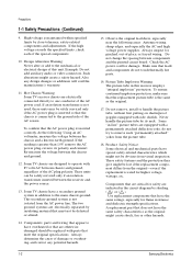
... Example: Do not add auxiliary audio or video connectors. To confirm that must not be replaced with side shields. Some TV chassis are designed to operate with a permanently attached deflection yoke; The two ground systems are equipped with 85 volts AC between... not touch thermally hot parts. 16. These safety features and the protection they give might create a safety hazard. Samsung Electronics Precautions 1-1 Safety Precautions (Continued) 9. Some TV chassis have the same ratings, especially for higher voltage, wattage, etc. Also, any potential hazards. 1-2 15....
... Example: Do not add auxiliary audio or video connectors. To confirm that must not be replaced with side shields. Some TV chassis are designed to operate with a permanently attached deflection yoke; The two ground systems are equipped with 85 volts AC between... not touch thermally hot parts. 16. These safety features and the protection they give might create a safety hazard. Samsung Electronics Precautions 1-1 Safety Precautions (Continued) 9. Some TV chassis have the same ratings, especially for higher voltage, wattage, etc. Also, any potential hazards. 1-2 15....
Service Manual
Page 8
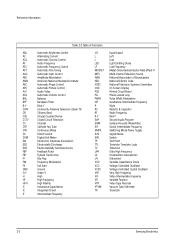
...Automatic Phase Control APC Automatic Picture Control A/V Audio-Video AVC Automatic Volume Control BAL Balance BPF Bandpass Filter B-Y Blue-Y CATV Community Antenna Television (Cable TV) CB Citizens Band CCD Charge Coupled Device CCTV Closed Circuit Television Ch Channel CRT Cathode Ray Tube CW Continuous Wave DC Direct Current DVM Digital... Diode Voltage Controlled Oscillator Voltage Controlled Crystal Oscillator Very High Frequency Video Intermediate Frequency Variable Resistor Video Tape Recorder Vacuum Tube Voltmeter Transistor 2-2 Samsung Electronics
...Automatic Phase Control APC Automatic Picture Control A/V Audio-Video AVC Automatic Volume Control BAL Balance BPF Bandpass Filter B-Y Blue-Y CATV Community Antenna Television (Cable TV) CB Citizens Band CCD Charge Coupled Device CCTV Closed Circuit Television Ch Channel CRT Cathode Ray Tube CW Continuous Wave DC Direct Current DVM Digital... Diode Voltage Controlled Oscillator Voltage Controlled Crystal Oscillator Very High Frequency Video Intermediate Frequency Variable Resistor Video Tape Recorder Vacuum Tube Voltmeter Transistor 2-2 Samsung Electronics

Service Manual
Page 16
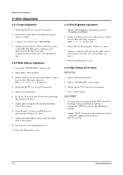
Turn off the TV (STAND-BY). 3. Turn on the TV, and then select "STANDARD"on the picture adjustment mode. 2. Initial display when the service mode is received SERVICE NORMAL 480P GEOMETRICS PICTURE PICTURE2 SOUND PIP ... necessary, re-do steps 1~3. When a RF signal is switched. 1. When a DTV signal is received SERVICE NORMAL 1080i GEOMETRICS PICTURE PICTURE2 SOUND PIP OPTION READ RESET Samsung Electronics 4-1
Turn off the TV (STAND-BY). 3. Turn on the TV, and then select "STANDARD"on the picture adjustment mode. 2. Initial display when the service mode is received SERVICE NORMAL 480P GEOMETRICS PICTURE PICTURE2 SOUND PIP ... necessary, re-do steps 1~3. When a RF signal is switched. 1. When a DTV signal is received SERVICE NORMAL 1080i GEOMETRICS PICTURE PICTURE2 SOUND PIP OPTION READ RESET Samsung Electronics 4-1

Service Manual
Page 18
4-2 Facotry Data 4-2-1 Progressive GEOMETRIC TV/480P Item Item 43" 53" 61" VS 132 132 114 VS VA 122 122 88 VA VL 114 114 114 VL VSC 104 104 104 ... 91 75 114 104 0 114 100 96 96 128 128 0 65 62 131 128 139 150 125 96 53 56 45 106 54 131 Remark Samsung Electronics 4-3
4-2 Facotry Data 4-2-1 Progressive GEOMETRIC TV/480P Item Item 43" 53" 61" VS 132 132 114 VS VA 122 122 88 VA VL 114 114 114 VL VSC 104 104 104 ... 91 75 114 104 0 114 100 96 96 128 128 0 65 62 131 128 139 150 125 96 53 56 45 106 54 131 Remark Samsung Electronics 4-3

Service Manual
Page 24
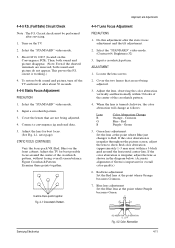
... the 4-pole of the 2-pole/4-pole zero magnets) ADJUSTMENT 1. CORE 2. Adjust the G-Focus until the light around the core disappears. Samsung Electronics 4-9 Input a crosshatch and dot pattern. 2. Warm up the TV for at the point where the focus is misaligned (Use an audio oscillator). (Creation of CPM Zero Magnet) (Creation of VM...
... the 4-pole of the 2-pole/4-pole zero magnets) ADJUSTMENT 1. CORE 2. Adjust the G-Focus until the light around the core disappears. Samsung Electronics 4-9 Input a crosshatch and dot pattern. 2. Warm up the TV for at the point where the focus is misaligned (Use an audio oscillator). (Creation of CPM Zero Magnet) (Creation of VM...
Service Manual
Page 25
... at least 30 minutes. 5. keys. 9. Select SBT by pressing the Volume +/- Select "STANDARD" video mode. 3. Warm up the TV for at least 10 minutes. 4. keys. 7. Select R-drive, G-drive, and B-drive by mode, press the remote-control keys in the following sequence : Mute - 1 -...4-4-2 White Balance Adjustment 1. Adjust the VR (VR501, VR531, VR561) screen so that the digital meter indicates DC 31V ± 0.1V. 4-10 Samsung Electronics keys. 4. Press the Menu key to exit. 4-4-3 Sub-Brightness Adjustment 1. In the stand-by pressing the Volume +/- Adjust the low light ...
... at least 30 minutes. 5. keys. 9. Select SBT by pressing the Volume +/- Select "STANDARD" video mode. 3. Warm up the TV for at least 10 minutes. 4. keys. 7. Select R-drive, G-drive, and B-drive by mode, press the remote-control keys in the following sequence : Mute - 1 -...4-4-2 White Balance Adjustment 1. Adjust the VR (VR501, VR531, VR561) screen so that the digital meter indicates DC 31V ± 0.1V. 4-10 Samsung Electronics keys. 4. Press the Menu key to exit. 4-4-3 Sub-Brightness Adjustment 1. In the stand-by pressing the Volume +/- Adjust the low light ...
Service Manual
Page 26
...of the center of the crosshatch pattern, without losing overall screen balance. Turn on the Convergence PCB). Short GT18, GT17 (located on the TV. 2. Select the "STANDARD" video mode. (Contrast:64, Brightness:32) 3. Adjust the lens, observing the color aberration vertically and horizontally... pattern. 4. Crimson Blue - Green 5. Green lens adjustment: Set the lens at the point where Orange becomes Crimson. 7. P L1 L2 Samsung Electronics RED ABERRATION BLUE ABERRATION L1, L2_< P Fig. 4-2 Color Aberration 4-11 This proves the F.S. Cover the lenses that are not being...
...of the center of the crosshatch pattern, without losing overall screen balance. Turn on the Convergence PCB). Short GT18, GT17 (located on the TV. 2. Select the "STANDARD" video mode. (Contrast:64, Brightness:32) 3. Adjust the lens, observing the color aberration vertically and horizontally... pattern. 4. Crimson Blue - Green 5. Green lens adjustment: Set the lens at the point where Orange becomes Crimson. 7. P L1 L2 Samsung Electronics RED ABERRATION BLUE ABERRATION L1, L2_< P Fig. 4-2 Color Aberration 4-11 This proves the F.S. Cover the lenses that are not being...

Service Manual
Page 33
... are completed, press to save data. 13 EXIT BUTTON After the Convergence adjustments are completed, press to exit to mute BLUE color. 7. B-MUTE Press to TV mode. 4-18 Samsung Electronics TEST/NORMAL Press to the previous data during the Convergence Adjustment. 8. CANCEL KEY Press to revert to check...
... are completed, press to save data. 13 EXIT BUTTON After the Convergence adjustments are completed, press to exit to mute BLUE color. 7. B-MUTE Press to TV mode. 4-18 Samsung Electronics TEST/NORMAL Press to the previous data during the Convergence Adjustment. 8. CANCEL KEY Press to revert to check...
Service Manual
Page 41
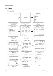
Alignment and Adjustments 4-8 PC Mode 4-8-1 TV Setup Mode 4-26 Samsung Electronics
Alignment and Adjustments 4-8 PC Mode 4-8-1 TV Setup Mode 4-26 Samsung Electronics

Service Manual
Page 54
4-9-5 PIP Module PIN NO. 1 2 3 4 5 6 7 8 9 10 11 12 13 14 15 16 17 18 19 20 21 22 ITEM GND TV GND N.C 8V N.C PIP-Pr/R PIP-Y/G PIP-Pb/B PIP-FB 12V PIP-F/B PIP-B PIP-G PIP-R N.C V-SYNC H-SYNC SCL SDA 5V GND FUNCTION GND SUB-V INPUT GND N.C 8V INPUT N.C PIP-Pr/R (DVD SIG) OUT PIP-Y/G (DVD SIG) OUT PIP-Pb/B (DVD SIG) OUT PIP FAST BLANKING 12V INPUT N.C DVD-B IN DVD-G IN DVD-R IN N.C V-SYNC INPUT H-SYNC INPUT SERIAL CLOCK LINE SERIAL DATA LINE 5V INPUT GND Alignment and Adjustments OUT VOLT GND 2.93V GND 8V 2.02V 2.04V 2.02V 2.02V 12V N.C 4.11V 4.5V 5V GND Samsung Electronics 4-39
4-9-5 PIP Module PIN NO. 1 2 3 4 5 6 7 8 9 10 11 12 13 14 15 16 17 18 19 20 21 22 ITEM GND TV GND N.C 8V N.C PIP-Pr/R PIP-Y/G PIP-Pb/B PIP-FB 12V PIP-F/B PIP-B PIP-G PIP-R N.C V-SYNC H-SYNC SCL SDA 5V GND FUNCTION GND SUB-V INPUT GND N.C 8V INPUT N.C PIP-Pr/R (DVD SIG) OUT PIP-Y/G (DVD SIG) OUT PIP-Pb/B (DVD SIG) OUT PIP FAST BLANKING 12V INPUT N.C DVD-B IN DVD-G IN DVD-R IN N.C V-SYNC INPUT H-SYNC INPUT SERIAL CLOCK LINE SERIAL DATA LINE 5V INPUT GND Alignment and Adjustments OUT VOLT GND 2.93V GND 8V 2.02V 2.04V 2.02V 2.02V 12V N.C 4.11V 4.5V 5V GND Samsung Electronics 4-39
Service Manual
Page 55
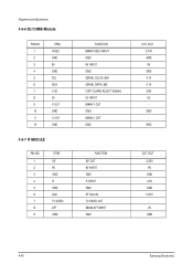
Alignment and Adjustments 4-9-6 3D/COMB Module PIN NO. 1 2 3 4 5 6 7 8 9 10 11 12 ITEM VIDEO GND 9V GND SCL SDA V-3D 5V Y-OUT GND C-OUT GND 4-9-7 IF MODULE PIN NO. 1 2 3 4 5 6 7 8 9 ITEM SIF 9V GND IF GND AGC TV-VIDEO AFT GND FUNCTION MAIN VIDEO INPUT GND 9V INPUT GND SERIAL CLOCK LINE SERIAL DATA LINE COPY GUARD REJECT SIGNAL 5V INPUT MAIN Y OUT GND MAIN C OUT GND OUT VOLT 2.74V GND 9V GND 4.1V 4.1V 3.8V 5V GND GND FUNCTION SIF OUT 9V INPUT GND IF INPUT GND RF AGC IN TV-VIDEO OUT MAIN AFT INPUT GND OUT VOLT 3.25V 9V GND 4.5V GND 5.37V 2V GND 4-40 Samsung Electronics
Alignment and Adjustments 4-9-6 3D/COMB Module PIN NO. 1 2 3 4 5 6 7 8 9 10 11 12 ITEM VIDEO GND 9V GND SCL SDA V-3D 5V Y-OUT GND C-OUT GND 4-9-7 IF MODULE PIN NO. 1 2 3 4 5 6 7 8 9 ITEM SIF 9V GND IF GND AGC TV-VIDEO AFT GND FUNCTION MAIN VIDEO INPUT GND 9V INPUT GND SERIAL CLOCK LINE SERIAL DATA LINE COPY GUARD REJECT SIGNAL 5V INPUT MAIN Y OUT GND MAIN C OUT GND OUT VOLT 2.74V GND 9V GND 4.1V 4.1V 3.8V 5V GND GND FUNCTION SIF OUT 9V INPUT GND IF INPUT GND RF AGC IN TV-VIDEO OUT MAIN AFT INPUT GND OUT VOLT 3.25V 9V GND 4.5V GND 5.37V 2V GND 4-40 Samsung Electronics

Service Manual
Page 73
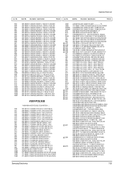
...,DISC;0.47nF,10%,1kV,Y5P,TP,6.3 2401-000133 C-AL;1000uF,20%,16V,GP,TP,10x20,5 2201-000551 C-CERAMIC,DISC;0.47nF,10%,1kV,Y5P,TP,6.3 7-8 Samsung Electronics Specification Remark CN402 CN801 CN802 CNW406 CNW809 D464 D810 D871 DZ833 F801 F802 F804 IC421 IC430 IC431 IC802 IC804 IC806 L431 L432 L800 L801...0402-000236 DIODE-RECTIFIER;GI824,400V,5A,-,TP 0402-000250 DIODE-RECTIFIER;RG4C,1000V,1A,AA96-00032AASSY-H/S;-,-,AA62-30173B,FMLG12, FMGG26 0406-001007 DIODE-TVS;P6KE180A,171/180/189V,600W,CAS 3601-000300 FUSE-CARTRIDGE;250V,6.3A,SLOW-BLOW,GLASS 3601-001137 FUSE-AXIAL LEAD;250V,6A,SLOW-BLOW,GLASS...
...,DISC;0.47nF,10%,1kV,Y5P,TP,6.3 2401-000133 C-AL;1000uF,20%,16V,GP,TP,10x20,5 2201-000551 C-CERAMIC,DISC;0.47nF,10%,1kV,Y5P,TP,6.3 7-8 Samsung Electronics Specification Remark CN402 CN801 CN802 CNW406 CNW809 D464 D810 D871 DZ833 F801 F802 F804 IC421 IC430 IC431 IC802 IC804 IC806 L431 L432 L800 L801...0402-000236 DIODE-RECTIFIER;GI824,400V,5A,-,TP 0402-000250 DIODE-RECTIFIER;RG4C,1000V,1A,AA96-00032AASSY-H/S;-,-,AA62-30173B,FMLG12, FMGG26 0406-001007 DIODE-TVS;P6KE180A,171/180/189V,600W,CAS 3601-000300 FUSE-CARTRIDGE;250V,6.3A,SLOW-BLOW,GLASS 3601-001137 FUSE-AXIAL LEAD;250V,6A,SLOW-BLOW,GLASS...
Service Manual
Page 90
...,100 0402-000236 DIODE-RECTIFIER;GI824,400V,5A,-,TP 0402-000250 DIODE-RECTIFIER;RG4C,1000V,1A,AA96-00032AASSY-H/S;-,-,AA62-30173B,FMLG12, FMGG26 0406-001007 DIODE-TVS;P6KE180A,171/180/189V,600W,CAS 3601-000300 FUSE-CARTRIDGE;250V,6.3A,SLOW-BLOW,GLASS 3601-001137 FUSE-AXIAL LEAD;250V,6A,SLOW-BLOW,GLASS... 6003-000333 SCREW-TAPTITE;RH,+,2S,M3,L10,ZPC(YEL),SW 0505-001202 FET-SILICON;IRFS640A,N,200V,9.8A,0.18ohm 0205-000129 GREASE-SILICON;SC102,JAPAN Samsung Electronics 7-25 Description ; Code No. Description ; Electrical Parts List Loc. Code No.
...,100 0402-000236 DIODE-RECTIFIER;GI824,400V,5A,-,TP 0402-000250 DIODE-RECTIFIER;RG4C,1000V,1A,AA96-00032AASSY-H/S;-,-,AA62-30173B,FMLG12, FMGG26 0406-001007 DIODE-TVS;P6KE180A,171/180/189V,600W,CAS 3601-000300 FUSE-CARTRIDGE;250V,6.3A,SLOW-BLOW,GLASS 3601-001137 FUSE-AXIAL LEAD;250V,6A,SLOW-BLOW,GLASS... 6003-000333 SCREW-TAPTITE;RH,+,2S,M3,L10,ZPC(YEL),SW 0505-001202 FET-SILICON;IRFS640A,N,200V,9.8A,0.18ohm 0205-000129 GREASE-SILICON;SC102,JAPAN Samsung Electronics 7-25 Description ; Code No. Description ; Electrical Parts List Loc. Code No.


