

Service Manual
Page 1
Alignment and Adjustments 5. Electrical Parts List 8. Precautions 2. Block Diagrams 9. Troubleshooting 6. Exploded View and Parts List 7. Reference Information 3. Wiring Diagram 10. Schematic Diagrams Specifications 4. PROJECTION TV RECEIVER Chassis : Model : P51A (REV. 1) PCJ534RF3C/XAA PCJ534RFX/XTC PCJ614RF3C/XAA PROJECTION TV RECEIVER CONTENTS 1.
Alignment and Adjustments 5. Electrical Parts List 8. Precautions 2. Block Diagrams 9. Troubleshooting 6. Exploded View and Parts List 7. Reference Information 3. Wiring Diagram 10. Schematic Diagrams Specifications 4. PROJECTION TV RECEIVER Chassis : Model : P51A (REV. 1) PCJ534RF3C/XAA PCJ534RFX/XTC PCJ614RF3C/XAA PROJECTION TV RECEIVER CONTENTS 1.
Service Manual
Page 3
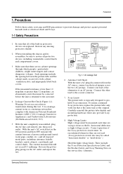
... the AC line cord directly into the power outlet. With the unit's AC switch first in the ON position and then OFF, measure the current between the picture tube and the cabinet mask, excessively wide cabinet ventilation slots, and improperly fitted back covers. Antenna Cold Check: With the unit's AC plug disconnected from the AC source, connect an electrical jumper...
... the AC line cord directly into the power outlet. With the unit's AC switch first in the ON position and then OFF, measure the current between the picture tube and the cabinet mask, excessively wide cabinet ventilation slots, and improperly fitted back covers. Antenna Cold Check: With the unit's AC plug disconnected from the AC source, connect an electrical jumper...
Service Manual
Page 4
... areas: Antenna wiring, sharp edges, and especially the AC and high voltage power supplies. These units can be safely serviced only if the AC power plug is inserted so that the AC power plug is connected to the ground side of the AC source. Picture Tube Implosion Warning: The picture tube in addition to operate with a permanently attached deflection yoke; Do not remove, install or...
... areas: Antenna wiring, sharp edges, and especially the AC and high voltage power supplies. These units can be safely serviced only if the AC power plug is inserted so that the AC power plug is connected to the ground side of the AC source. Picture Tube Implosion Warning: The picture tube in addition to operate with a permanently attached deflection yoke; Do not remove, install or...
Service Manual
Page 5
... any of this manual. Always connect a test instrument's ground lead to prevent contact with thermally hot components. always remove the instrument's ground lead last. 9. The internal wiring is sometimes used. If some parts inside the optical engine (except lamp) are correctly installed. 8. Some components are printed on the cabinet. Insulation Checking Procedure: Disconnect the power cord from the AC power source before connecting the positive...
... any of this manual. Always connect a test instrument's ground lead to prevent contact with thermally hot components. always remove the instrument's ground lead last. 9. The internal wiring is sometimes used. If some parts inside the optical engine (except lamp) are correctly installed. 8. Some components are printed on the cabinet. Insulation Checking Procedure: Disconnect the power cord from the AC power source before connecting the positive...
Service Manual
Page 8
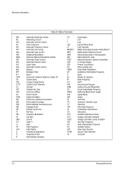
...-Tr Multi-channel Television Sound National Association of Broadcasters National Electric Code National Television Systems Committee On Screen Display Printed Circuit Board Phase-Locked Loop Pulse Width Modulation Quadrature Intermediate Frequency Right Resistor & Capacitor Radio Frequency Red-Y Second Audio Program Surface Acoustic Wave(Filter) Sound Intermediate Frequency Switching Mode Power Supply Signal/Noise Switch Test Point Transistor Transistor Logic Television Ultra High Frequency Underwriters Laboratories Ultraviolet Variable-Capacitance Diode Voltage Controlled Oscillator Voltage...
...-Tr Multi-channel Television Sound National Association of Broadcasters National Electric Code National Television Systems Committee On Screen Display Printed Circuit Board Phase-Locked Loop Pulse Width Modulation Quadrature Intermediate Frequency Right Resistor & Capacitor Radio Frequency Red-Y Second Audio Program Surface Acoustic Wave(Filter) Sound Intermediate Frequency Switching Mode Power Supply Signal/Noise Switch Test Point Transistor Transistor Logic Television Ultra High Frequency Underwriters Laboratories Ultraviolet Variable-Capacitance Diode Voltage Controlled Oscillator Voltage...

Service Manual
Page 16
Turn off the TV (STAND-BY). 3. When a DTV signal is switched. 1. Turn on the TV, and then select "STANDARD"on the picture adjustment mode. 2. Initial display when the service mode is received SERVICE NORMAL 1080i GEOMETRICS PICTURE PICTURE2 SOUND PIP OPTION READ RESET Samsung Electronics 4-1 Alignment and Adjustments 4-1 When entering the service mode: 1. When a RF signal is received SERVICE NORMAL 480P GEOMETRICS PICTURE PICTURE2 SOUND PIP OPTION READ RESET 2. Enter the service mode by pressing the remote control keys in the following sequence : MUTE 1→...
Turn off the TV (STAND-BY). 3. When a DTV signal is switched. 1. Turn on the TV, and then select "STANDARD"on the picture adjustment mode. 2. Initial display when the service mode is received SERVICE NORMAL 1080i GEOMETRICS PICTURE PICTURE2 SOUND PIP OPTION READ RESET Samsung Electronics 4-1 Alignment and Adjustments 4-1 When entering the service mode: 1. When a RF signal is received SERVICE NORMAL 480P GEOMETRICS PICTURE PICTURE2 SOUND PIP OPTION READ RESET 2. Enter the service mode by pressing the remote control keys in the following sequence : MUTE 1→...

Service Manual
Page 17
Alignment and Adjustments 3. When the PC mode is switched MAIN MENU ZOOM COMPRESS FREEZE SET UP RESET EXIT 4. Service Mode Control Keys MAIN MENU MENU DISPLAY CH UP/DOWN Select item by moving cursor VOL UP/DOWN Decrease or increase the adjustment values Note : The PC mode can be switched to the service mode by pressing the F.Mode Key (only on the factory remote control). 4-2 Samsung Electronics
Alignment and Adjustments 3. When the PC mode is switched MAIN MENU ZOOM COMPRESS FREEZE SET UP RESET EXIT 4. Service Mode Control Keys MAIN MENU MENU DISPLAY CH UP/DOWN Select item by moving cursor VOL UP/DOWN Decrease or increase the adjustment values Note : The PC mode can be switched to the service mode by pressing the F.Mode Key (only on the factory remote control). 4-2 Samsung Electronics

Service Manual
Page 22
Alignment and Adjustments Note 1 SZM-386U OPTION TABLE Option adjustment is done in the service mode Byte : 00 D7 D6 D5 D4 D3 D2 D1 D0 Name SharpCenter50En CXA1839(DVD) V-Chip AFN Auto Power On Function 0 1 X Operate Sharpness, Color, Tint adjustment available in the DVD Menu X Sharpness, Color, Tint not adjustable in the DVD Menu Operate Remark X Operate X Operate Current Set Setting Byte : 01 D7 D6 D5 D4 D3 D2 D1 D0 Name 3D Comb-filter All Mighty Conv. Function 0 1 UPD6488 UPD64082 X Operate Remark Samsung Electronics 4-7
Alignment and Adjustments Note 1 SZM-386U OPTION TABLE Option adjustment is done in the service mode Byte : 00 D7 D6 D5 D4 D3 D2 D1 D0 Name SharpCenter50En CXA1839(DVD) V-Chip AFN Auto Power On Function 0 1 X Operate Sharpness, Color, Tint adjustment available in the DVD Menu X Sharpness, Color, Tint not adjustable in the DVD Menu Operate Remark X Operate X Operate Current Set Setting Byte : 01 D7 D6 D5 D4 D3 D2 D1 D0 Name 3D Comb-filter All Mighty Conv. Function 0 1 UPD6488 UPD64082 X Operate Remark Samsung Electronics 4-7

Service Manual
Page 24
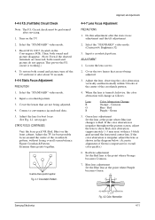
... the 4-pole of the 2-pole/4-pole zero magnets) ADJUSTMENT 1. Cover the Green and Blue lenses. 5. Input a crosshatch and dot pattern. 2. Check the squarewave at least 10 minutes. 4. Alignment and Adjustments 4-3 Beam Alignment PRECAUTION 1. Adjust the Green lens as with the Green lens. 6. CoGv-eFOr CtUhSe Red and Blue lenses. Select the "STANDARD" video mode. 3. Warm up the TV for at the point where the focus is installed). 7.
... the 4-pole of the 2-pole/4-pole zero magnets) ADJUSTMENT 1. Cover the Green and Blue lenses. 5. Input a crosshatch and dot pattern. 2. Check the squarewave at least 10 minutes. 4. Alignment and Adjustments 4-3 Beam Alignment PRECAUTION 1. Adjust the Green lens as with the Green lens. 6. CoGv-eFOr CtUhSe Red and Blue lenses. Select the "STANDARD" video mode. 3. Warm up the TV for at the point where the focus is installed). 7.
Service Manual
Page 25
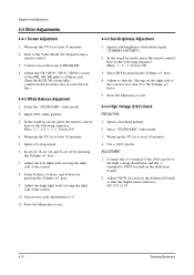
... the Volume +/- Input a sub-brightness adjustment signal. (TOSHIBA PATTERN) 2. keys. 4. Select "STANDARD" video mode. 3. Warm up the TV for at least 10 minutes. 4. If necessary, redo adjustments 6~9. 11. Power ON 3. Turn to RK,GK,BK. 4. Adjust the high light with viewing the dark side of the screen. 8. Adjust so that the digital meter indicates DC 31V ± 0.1V. 4-10 Samsung Electronics Connect an oscilloscope to the Video Mode (No Signal) using a remote-control. 3. Warm up the TV for...
... the Volume +/- Input a sub-brightness adjustment signal. (TOSHIBA PATTERN) 2. keys. 4. Select "STANDARD" video mode. 3. Warm up the TV for at least 10 minutes. 4. If necessary, redo adjustments 6~9. 11. Power ON 3. Turn to RK,GK,BK. 4. Adjust the high light with viewing the dark side of the screen. 8. Adjust so that the digital meter indicates DC 31V ± 0.1V. 4-10 Samsung Electronics Connect an oscilloscope to the Video Mode (No Signal) using a remote-control. 3. Warm up the TV for...
Service Manual
Page 26
... "STANDARD" video mode. 2. Cover the lenses that are removed, both sound and picture, turn off the TV and reset it after about 30 seconds. 4-4-6 Static Focus Adjustment PRECAUTION 1. Crimson Blue - Green 5. Input a crosshatch pattern. Circuit check must be performed after the static focus adjustment and the tilt adjustment. 2. Select the "STANDARD" video mode. 3. Adjust the lens for overall color quality.) 6. Green lens adjustment: Set the lens at the point where Blue just changes to show Red color aberration (approximately...
... "STANDARD" video mode. 2. Cover the lenses that are removed, both sound and picture, turn off the TV and reset it after about 30 seconds. 4-4-6 Static Focus Adjustment PRECAUTION 1. Crimson Blue - Green 5. Input a crosshatch pattern. Circuit check must be performed after the static focus adjustment and the tilt adjustment. 2. Select the "STANDARD" video mode. 3. Adjust the lens for overall color quality.) 6. Green lens adjustment: Set the lens at the point where Blue just changes to show Red color aberration (approximately...
Service Manual
Page 27
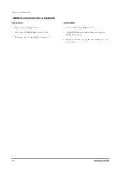
ADJUSTMENT 1. Warm up the set for at least 10 minutes. Input a crosshatch pattern. 2. Cover the Red and Blue lenses. 2. Adjust VR491 (located on the convergence PCB, H-Parabola). 3. Select the "STANDARD" video mode. 3. Balance the left and right sides of the dynamic focus lines. 4-12 Samsung Electronics Alignment and Adjustments 4-4-8 Horizontal Dynamic Focus Adjustment PRECAUTION 1.
ADJUSTMENT 1. Warm up the set for at least 10 minutes. Input a crosshatch pattern. 2. Cover the Red and Blue lenses. 2. Adjust VR491 (located on the convergence PCB, H-Parabola). 3. Select the "STANDARD" video mode. 3. Balance the left and right sides of the dynamic focus lines. 4-12 Samsung Electronics Alignment and Adjustments 4-4-8 Horizontal Dynamic Focus Adjustment PRECAUTION 1.

Service Manual
Page 33
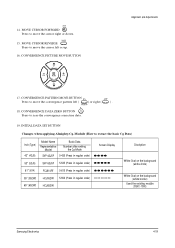
... EXIT BUTTON After the Convergence adjustments are completed, press to exit to move a line up/down or left/right. 10. LINE SHIFT Press to TV mode. 4-18 Samsung Electronics G-SELECT Press to mute GREEN color. 6. G-MUTE Press to select GREEN color. 3. B-SELECT Press to call the factory default values. 11. FACTORY DATA SELECT BUTTON Press to select BLUE color. 4. Alignment and Adjustments 4-6-1 KEY Function 1. R-SELECT Press to mute RED color...
... EXIT BUTTON After the Convergence adjustments are completed, press to exit to move a line up/down or left/right. 10. LINE SHIFT Press to TV mode. 4-18 Samsung Electronics G-SELECT Press to mute GREEN color. 6. G-MUTE Press to select GREEN color. 3. B-SELECT Press to call the factory default values. 11. FACTORY DATA SELECT BUTTON Press to select BLUE color. 4. Alignment and Adjustments 4-6-1 KEY Function 1. R-SELECT Press to mute RED color...
Service Manual
Page 34
CONVERGENCE PICTURE MOVE BUTTON Alignment and Adjustments 17. INITIAL DATA SET BUTTON Changes when applying Almighty-Cg, Module (How to zero the convergence correction data. 19. MOVE CURSOR REVERSE Press to move the cursor right or down. 15. CONVERGENCE DATA ZERO BUTTON Press to extract the basic Cg Data) Inch (Type) 43" (43J5) Model Name Representative Model Basic Data Number after entring the Cg-Mode SVP...
CONVERGENCE PICTURE MOVE BUTTON Alignment and Adjustments 17. INITIAL DATA SET BUTTON Changes when applying Almighty-Cg, Module (How to zero the convergence correction data. 19. MOVE CURSOR REVERSE Press to move the cursor right or down. 15. CONVERGENCE DATA ZERO BUTTON Press to extract the basic Cg Data) Inch (Type) 43" (43J5) Model Name Representative Model Basic Data Number after entring the Cg-Mode SVP...

Service Manual
Page 35
Alignment and Adjustments 4-7 Convergence Adjustment 4-20 Samsung Electronics
Alignment and Adjustments 4-7 Convergence Adjustment 4-20 Samsung Electronics

Service Manual
Page 46
... R Samsung Electronics Alignment and Adjustments FUNCTION POWER ON/OFF RELAY CONTROL REMOCON INPUT VIDEO SIGNAL MUTE 3D PHONIC DATA LINE 3D PHONIC CLOCK LINE 3D PHONIC ENABLE LINE VALID DTV SIGNAL (LOW) MODE SELECTOR CONTROL PROTECT PORT NORMAL H,V-SYNC CLOCK BUS LINE DATA BUS LINE CVBS LOOP FILTER GND SUB AUTO FINE TURNING CONTROL KEY SCAN 1 MAIN TUNER AFT KEY SCAN 2 KEY SCAN 3 GND VCC SIGNAL FOR OSC-FREQUENCY OSD CONTROL ON SCREEN DISPLAY BLUE OUTPUT ON SCREEN DISPLAY GREEN OUTPUT ON SCREEN DISPLAY RED OUTPUT...
... R Samsung Electronics Alignment and Adjustments FUNCTION POWER ON/OFF RELAY CONTROL REMOCON INPUT VIDEO SIGNAL MUTE 3D PHONIC DATA LINE 3D PHONIC CLOCK LINE 3D PHONIC ENABLE LINE VALID DTV SIGNAL (LOW) MODE SELECTOR CONTROL PROTECT PORT NORMAL H,V-SYNC CLOCK BUS LINE DATA BUS LINE CVBS LOOP FILTER GND SUB AUTO FINE TURNING CONTROL KEY SCAN 1 MAIN TUNER AFT KEY SCAN 2 KEY SCAN 3 GND VCC SIGNAL FOR OSC-FREQUENCY OSD CONTROL ON SCREEN DISPLAY BLUE OUTPUT ON SCREEN DISPLAY GREEN OUTPUT ON SCREEN DISPLAY RED OUTPUT...

Service Manual
Page 48
... TONE 24 OSD B 25 OSD G 26 OSD R Samsung Electronics Alignment and Adjustments FUNCTION POWER ON/OFF RELAY CONTROL REMOCON INPUT VIDEO SIGNAL MUTE N.C N.C CONTROL-3PORT N.C N.C PROTECT PORT N.C CLOCK BUS LINE DATA BUS LINE CVBS LOOP FILTER GND SUB AUTO FINE TURNING CONTROL KEY SCAN 1 MAIN TUNER AFT KEY SCAN 2 KEY SCAN 3 GND VCC SIGNAL FOR OSC-FREQUENCY OSD CONTROL ON SCREEN DISPLAY BLUE OUTPUT ON SCREEN DISPLAY GREEN OUTPUT ON SCREEN DISPLAY RED OUTPUT OUT VOLT H--> L 5V 3V 5V 4.5V 4.5V...
... TONE 24 OSD B 25 OSD G 26 OSD R Samsung Electronics Alignment and Adjustments FUNCTION POWER ON/OFF RELAY CONTROL REMOCON INPUT VIDEO SIGNAL MUTE N.C N.C CONTROL-3PORT N.C N.C PROTECT PORT N.C CLOCK BUS LINE DATA BUS LINE CVBS LOOP FILTER GND SUB AUTO FINE TURNING CONTROL KEY SCAN 1 MAIN TUNER AFT KEY SCAN 2 KEY SCAN 3 GND VCC SIGNAL FOR OSC-FREQUENCY OSD CONTROL ON SCREEN DISPLAY BLUE OUTPUT ON SCREEN DISPLAY GREEN OUTPUT ON SCREEN DISPLAY RED OUTPUT OUT VOLT H--> L 5V 3V 5V 4.5V 4.5V...
Service Manual
Page 66
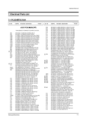
...TUNER-F/S;TCPN9082PC27P(S),NTSC,TR,181CH AA59-40003Q MODULE-MTS;-,MZ-201,ZENITH,US,43X54,AA13-00012A IC-MCU;Z9037112PSC-OTP,OTP,ST,64kword AA27-10001C COIL-CHOKE;-,100uH,K,-,5.0A,ST,700UH-K(R AA29-00004AFILTER-LINE NOISE;-,20UH,3A,AC80-260V,TQ 3501-001053 RELAY-POWER;5VDC,530MW,10A,1FORMA,15MS,5 AA26-00019A TRANS-SWITCHING...CERAMIC,DISC;100nF,+80-20%,50V,Y5V,TP, 2401-000603 C-AL;1uF,20%,50V,GP,TP,5x11,5 Samsung Electronics 7-1 Electrical Parts List 7-1 PCJ534RF3C/XAA Loc. Electrical Parts List 7. Code No. AA94-02599L ,ER 2201-000446 C-CERAMIC,DISC;3.3nF,20%,400V,Y5U,TP,15x 2201-000446 C-...
...TUNER-F/S;TCPN9082PC27P(S),NTSC,TR,181CH AA59-40003Q MODULE-MTS;-,MZ-201,ZENITH,US,43X54,AA13-00012A IC-MCU;Z9037112PSC-OTP,OTP,ST,64kword AA27-10001C COIL-CHOKE;-,100uH,K,-,5.0A,ST,700UH-K(R AA29-00004AFILTER-LINE NOISE;-,20UH,3A,AC80-260V,TQ 3501-001053 RELAY-POWER;5VDC,530MW,10A,1FORMA,15MS,5 AA26-00019A TRANS-SWITCHING...CERAMIC,DISC;100nF,+80-20%,50V,Y5V,TP, 2401-000603 C-AL;1uF,20%,50V,GP,TP,5x11,5 Samsung Electronics 7-1 Electrical Parts List 7-1 PCJ534RF3C/XAA Loc. Electrical Parts List 7. Code No. AA94-02599L ,ER 2201-000446 C-CERAMIC,DISC;3.3nF,20%,400V,Y5U,TP,15x 2201-000446 C-...
Service Manual
Page 76
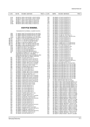
Specification Remark Loc. Code No. Description ; No. Code No. Specification Remark RZ146 RZ147 RZ148 RZ148A RZ149 RZ149A 2003-002148 R-METAL OXIDE;3.9OHM,2%,2W,AF...BOX,12P,1R,2.5mm,ANGLE, 3711-000447 CONNECTOR-HEADER;3WALL,3P,1R,2.5mm,ANGLE 1204-001222 IC-AUDIO PROCESSOR;TDA7429,DIP,44P,-,PLA 1201-000191 IC-OP AMP;4558,DIP,8P,300MIL,DUAL,20V/mV 0904-001121 IC-I/O SUPPORT CHIP;8574,8BIT,DIP,16P,30 1001-000212 IC-VIDEO SWITCH...(S);100KOHM,5%,1/2W,AA,TP,2.4X6. 2001-000429 R-CARBON;1KOHM,5%,1/8W,AA,TP,1.8X3.2MM Samsung Electronics 7-11 Description ; Electrical Parts List Loc.
Specification Remark Loc. Code No. Description ; No. Code No. Specification Remark RZ146 RZ147 RZ148 RZ148A RZ149 RZ149A 2003-002148 R-METAL OXIDE;3.9OHM,2%,2W,AF...BOX,12P,1R,2.5mm,ANGLE, 3711-000447 CONNECTOR-HEADER;3WALL,3P,1R,2.5mm,ANGLE 1204-001222 IC-AUDIO PROCESSOR;TDA7429,DIP,44P,-,PLA 1201-000191 IC-OP AMP;4558,DIP,8P,300MIL,DUAL,20V/mV 0904-001121 IC-I/O SUPPORT CHIP;8574,8BIT,DIP,16P,30 1001-000212 IC-VIDEO SWITCH...(S);100KOHM,5%,1/2W,AA,TP,2.4X6. 2001-000429 R-CARBON;1KOHM,5%,1/8W,AA,TP,1.8X3.2MM Samsung Electronics 7-11 Description ; Electrical Parts List Loc.
Service Manual
Page 87
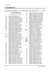
...TUNER-F/S;TCPN9082PC27P(S),NTSC,TR,181CH AA59-40003Q MODULE-MTS;-,MZ-201,ZENITH,US,43X54,AA13-00012A IC-MCU;Z9037112PSC-OTP,OTP,ST,64kword AA27-10001C COIL-CHOKE;-,100uH,K,-,5.0A,ST,700UH-K(R AA29-00004AFILTER-LINE NOISE;-,20UH,3A,AC80-260V,TQ 3501-001053 RELAY-POWER;5VDC,530MW,10A,1FORMA,15MS,5 AA26-00019A TRANS-SWITCHING...),SW AA62-30013K HEATSINK-ES;-,-,-,-,44/18,-,WHT,A6063 EX AA99-30179HASSY-PCB ROBOT; Electrical Parts List 7-2 PCJ614RF3C/XAA Loc. Specification Remark Loc. Description ; No. No. Code No. AA94-02599L ,ER 2201-000446 C-CERAMIC,DISC;3.3nF,20%,400V,Y5U,TP,15x ...
...TUNER-F/S;TCPN9082PC27P(S),NTSC,TR,181CH AA59-40003Q MODULE-MTS;-,MZ-201,ZENITH,US,43X54,AA13-00012A IC-MCU;Z9037112PSC-OTP,OTP,ST,64kword AA27-10001C COIL-CHOKE;-,100uH,K,-,5.0A,ST,700UH-K(R AA29-00004AFILTER-LINE NOISE;-,20UH,3A,AC80-260V,TQ 3501-001053 RELAY-POWER;5VDC,530MW,10A,1FORMA,15MS,5 AA26-00019A TRANS-SWITCHING...),SW AA62-30013K HEATSINK-ES;-,-,-,-,44/18,-,WHT,A6063 EX AA99-30179HASSY-PCB ROBOT; Electrical Parts List 7-2 PCJ614RF3C/XAA Loc. Specification Remark Loc. Description ; No. No. Code No. AA94-02599L ,ER 2201-000446 C-CERAMIC,DISC;3.3nF,20%,400V,Y5U,TP,15x ...


