

Owners Instructions
Page 1
Samsung SyncMaster 700s Color Monitor Owner's Instructions
Samsung SyncMaster 700s Color Monitor Owner's Instructions
Owners Instructions
Page 2
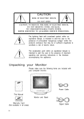
... equilateral triangle is intended to alert the user to constitute a risk of important operating and servicing instructions in all areas) ii Monitor and Stand Power Cable Signal Cable The exclamation point within the product's enclosure that may be of sufficient magnitude to the presence of electric shock. Unpacking your computer monitor: This Manual Warranty Card (Not available in the literature accompanying the...
... equilateral triangle is intended to alert the user to constitute a risk of important operating and servicing instructions in all areas) ii Monitor and Stand Power Cable Signal Cable The exclamation point within the product's enclosure that may be of sufficient magnitude to the presence of electric shock. Unpacking your computer monitor: This Manual Warranty Card (Not available in the literature accompanying the...
Owners Instructions
Page 3
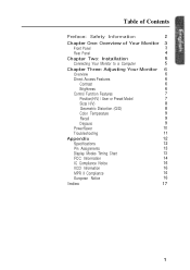
...: Safety Information 2 Chapter One: Overview of Your Monitor 3 Front Panel 3 Rear Panel 4 Chapter Two: Installation 5 Connecting Your Monitor to a Computer 5 Chapter Three: Adjusting Your Monitor 6 Overview 6 Direct Access Features 6 Contrast 6 Brightness 6 Control Function Features 7 Position(H/V) / User or Preset Model 7 Size( H/V) 8 Geometric Distortion (G/D) 8 Color Temperature 9 Recall 9 Degauss 9 PowerSaver 10 Troubleshooting 11 Appendix 12 Specifications 12 Pin Assignments 13 Display Modes Timing Chart 13 FCC Information 14 IC Compliance...
...: Safety Information 2 Chapter One: Overview of Your Monitor 3 Front Panel 3 Rear Panel 4 Chapter Two: Installation 5 Connecting Your Monitor to a Computer 5 Chapter Three: Adjusting Your Monitor 6 Overview 6 Direct Access Features 6 Contrast 6 Brightness 6 Control Function Features 7 Position(H/V) / User or Preset Model 7 Size( H/V) 8 Geometric Distortion (G/D) 8 Color Temperature 9 Recall 9 Degauss 9 PowerSaver 10 Troubleshooting 11 Appendix 12 Specifications 12 Pin Assignments 13 Display Modes Timing Chart 13 FCC Information 14 IC Compliance...

Owners Instructions
Page 4
... anything metallic into the monitor openings. in direct sunlight, and keep the cord away from it and contact an authorized dealer immediately. Also, avoid using your computer monitor. 1 Before connecting the AC power cord to an outlet, make sure the voltage designation on the power cord, and keep it away from heaters,... dealer or service center. 12 High temperatures can cause problems. Don't use your monitor in particular, if there are provided for an extended period of dust. Doing so may create the danger of electric shock. 3 To avoid electric shock, never touch the inside ...
... anything metallic into the monitor openings. in direct sunlight, and keep the cord away from it and contact an authorized dealer immediately. Also, avoid using your computer monitor. 1 Before connecting the AC power cord to an outlet, make sure the voltage designation on the power cord, and keep it away from heaters,... dealer or service center. 12 High temperatures can cause problems. Don't use your monitor in particular, if there are provided for an extended period of dust. Doing so may create the danger of electric shock. 3 To avoid electric shock, never touch the inside ...

Owners Instructions
Page 5
Chapter One: Overview of Your Monitor English Front Panel 1 Function control buttons Use these buttons to control the shape of the display area, and to control the color qualities of the display image. 2 Brightness Use this rotary control to adjust the overall brightness of the display image. 3 Contrast Use this rotary control to adjust the contrast level of the display image. 4 Power indicator This light glows green during normal operation, and glows amber when you are making adjustments. 5 Power button Use this button to turn the monitor on and off. 3
Chapter One: Overview of Your Monitor English Front Panel 1 Function control buttons Use these buttons to control the shape of the display area, and to control the color qualities of the display image. 2 Brightness Use this rotary control to adjust the overall brightness of the display image. 3 Contrast Use this rotary control to adjust the contrast level of the display image. 4 Power indicator This light glows green during normal operation, and glows amber when you are making adjustments. 5 Power button Use this button to turn the monitor on and off. 3

Owners Instructions
Page 6
Chapter One: Overview of Your Monitor 3 Rear Panel 1 Power port Connect the power cable here. 2 Signal port Connect your signal cable here. 4
Chapter One: Overview of Your Monitor 3 Rear Panel 1 Power port Connect the power cable here. 2 Signal port Connect your signal cable here. 4
Owners Instructions
Page 7
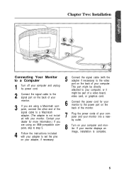
... might be part of a video board, video card, or graphics card. 6 Connect the power cord for more information.) If you are using a Macintosh computer, connect the other end of the signal cable to a Macintosh adapter. (The adapter is complete. 5 Chapter Two: Installation English Connecting Your Monitor to a Computer 1 Turn off your computer and unplug its power cord. 2 Connect the signal cable to the signal port on the back of your monitor. 3 If you are using an IBM-compatible computer, skip...
... might be part of a video board, video card, or graphics card. 6 Connect the power cord for more information.) If you are using a Macintosh computer, connect the other end of the signal cable to a Macintosh adapter. (The adapter is complete. 5 Chapter Two: Installation English Connecting Your Monitor to a Computer 1 Turn off your computer and unplug its power cord. 2 Connect the signal cable to the signal port on the back of your monitor. 3 If you are using an IBM-compatible computer, skip...

Owners Instructions
Page 8
... contrast between dark colors and light colors, or move it to the left to adjust the controls, an on-screen menu shows you use these adjustments are made using the control buttons on this page can be accessed quickly, at the touch of the monitor. Brightness This feature will adjust the monitor's contrast. All of these buttons to decrease the brightness. 6 Contrast This feature will adjust the overall brightness of the image being displayed. Rotate the rotary control...
... contrast between dark colors and light colors, or move it to the left to adjust the controls, an on-screen menu shows you use these adjustments are made using the control buttons on this page can be accessed quickly, at the touch of the monitor. Brightness This feature will adjust the monitor's contrast. All of these buttons to decrease the brightness. 6 Contrast This feature will adjust the overall brightness of the image being displayed. Rotate the rotary control...

Owners Instructions
Page 9
... instructions to change the position of the monitor's entire display. 1 Push this section can all be accessed using your changes when the OSD remains inactive for access, however some features require that you cannot adjust the display image while a control function is disabled (the indicator's color is orange. Use the adjustment control buttons (V and A) to change the vertical position. However, you push two buttons. Most features use the V and A buttons to change the horizontal position of the user modes...
... instructions to change the position of the monitor's entire display. 1 Push this section can all be accessed using your changes when the OSD remains inactive for access, however some features require that you cannot adjust the display image while a control function is disabled (the indicator's color is orange. Use the adjustment control buttons (V and A) to change the vertical position. However, you push two buttons. Most features use the V and A buttons to change the horizontal position of the user modes...
Owners Instructions
Page 10
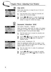
... edges. 1 Push this button once to adjust the horizontal and vertical size of the entire display. 2 Use the 4 and b buttons to change the horizontal size (width) of the entire display; use the V and A buttons to change the trapezoid setting. adjust the tilt setting when the display area appears rotated to the left or right; Chapter Three: Adjusting Your Monitor Size (H/V) Follow these instructions to change the size of the monitor's entire display. 1 Push this button once to access the...
... edges. 1 Push this button once to adjust the horizontal and vertical size of the entire display. 2 Use the 4 and b buttons to change the horizontal size (width) of the entire display; use the V and A buttons to change the trapezoid setting. adjust the tilt setting when the display area appears rotated to the left or right; Chapter Three: Adjusting Your Monitor Size (H/V) Follow these instructions to change the size of the monitor's entire display. 1 Push this button once to access the...

Owners Instructions
Page 11
Chapter Three: Adjusting Your Monitor COLOR TEMP. Push the button once to their original factory settings. Note : This operation resets all of the recall function. These effects are normal. If this button, a green LED indicates that the factory settings for the current video signal timing have been recalled. Color Temperature Follow these steps to change and the image will remove any color impurity caused by magnetic fields. After pushing this...
Chapter Three: Adjusting Your Monitor COLOR TEMP. Push the button once to their original factory settings. Note : This operation resets all of the recall function. These effects are normal. If this button, a green LED indicates that the factory settings for the current video signal timing have been recalled. Color Temperature Follow these steps to change and the image will remove any color impurity caused by magnetic fields. After pushing this...
Owners Instructions
Page 12
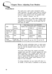
... been used with a computer equipped with a VESA DPMS compliant video card installed in power management system called PowerSaver. Chapter Three: Adjusting Your Monitor PowerSaver This monitor has a built-in your computer. This system operates with VESA DPMS functionality. If your monitor OFF when it unattended for details. State Normal Operation Horizontal Sync Active Vertical Sync Active Video Active Power Indicator Green Power Saving function mode EPA/NUTEK Standby mode Suspend mode Power-off Mode Position A1 Position...
... been used with a computer equipped with a VESA DPMS compliant video card installed in power management system called PowerSaver. Chapter Three: Adjusting Your Monitor PowerSaver This monitor has a built-in your computer. This system operates with VESA DPMS functionality. If your monitor OFF when it unattended for details. State Normal Operation Horizontal Sync Active Vertical Sync Active Video Active Power Indicator Green Power Saving function mode EPA/NUTEK Standby mode Suspend mode Power-off Mode Position A1 Position...

Owners Instructions
Page 13
.... l Adjust the Color Temperature settings. l Check to see that both the monitor and the computer are distorted with dark or shadowed areas. l Adjust the Brightness or Contrast settings. The image is amber, amber/green, or blinking. The image is using its power management system. l Adjust the Size settings. l The monitor is too light or too dark. Chapter Three: Adjusting Your Monitor Troubleshooting Before calling for service, check the information in and turned on. There is no screen image.
.... l Adjust the Color Temperature settings. l Check to see that both the monitor and the computer are distorted with dark or shadowed areas. l Adjust the Brightness or Contrast settings. The image is amber, amber/green, or blinking. The image is using its power management system. l Adjust the Size settings. l The monitor is too light or too dark. Chapter Three: Adjusting Your Monitor Troubleshooting Before calling for service, check the information in and turned on. There is no screen image.
Owners Instructions
Page 14
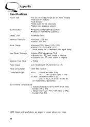
... to 160 Hz (automatic) Display Color Unlimited colors Maximum Resolution Horizontal: 1280 dots Vertical: 1024 lines Active Display Horizontal: 306 ± 3 mm (12.05"+ 0.12") Vertical: 230 ± 3 mm (9.06"+ 0.12") (Active display size is dependent upon signal timing) Input Signal, Terminated Analog 0.714 Vpp positive at 75 Ω Separate sync: TTL level, positive or negative Composite sync: TTL level, positive or negative Maximum Pixel Clock 110MHz Power Supply AC 100-240 Volt...
... to 160 Hz (automatic) Display Color Unlimited colors Maximum Resolution Horizontal: 1280 dots Vertical: 1024 lines Active Display Horizontal: 306 ± 3 mm (12.05"+ 0.12") Vertical: 230 ± 3 mm (9.06"+ 0.12") (Active display size is dependent upon signal timing) Input Signal, Terminated Analog 0.714 Vpp positive at 75 Ω Separate sync: TTL level, positive or negative Composite sync: TTL level, positive or negative Maximum Pixel Clock 110MHz Power Supply AC 100-240 Volt...

Owners Instructions
Page 15
... GND DDC Data H/V-Sync Not Used DDC Clock Cable Adapter (Figure 2 Apple MAC II GND-R Red H/V Sync Sense 0 Green GND-G Sense 1 Reserved Blue Sense 2 GND V-Sync GND-B GND H-Sync Figure 1 : Male Type Figure 2 : Male Type Display Modes Timing Chart Display Mode Horizontal Vertical Pixel Sync Polarity Frequency (kHz) Frequency (Hz) Clock (MHz) (H/V) IBM, VGA2, 720 x 400 IBM, VGA3, 640 x 480 VESA, 640 x 480 VESA, 800 x 600 VESA, 800 x 600 VESA, 1024 x 768 VESA, 1024 x 768 31...
... GND DDC Data H/V-Sync Not Used DDC Clock Cable Adapter (Figure 2 Apple MAC II GND-R Red H/V Sync Sense 0 Green GND-G Sense 1 Reserved Blue Sense 2 GND V-Sync GND-B GND H-Sync Figure 1 : Male Type Figure 2 : Male Type Display Modes Timing Chart Display Mode Horizontal Vertical Pixel Sync Polarity Frequency (kHz) Frequency (Hz) Clock (MHz) (H/V) IBM, VGA2, 720 x 400 IBM, VGA3, 640 x 480 VESA, 640 x 480 VESA, 800 x 600 VESA, 800 x 600 VESA, 1024 x 768 VESA, 1024 x 768 31...
Owners Instructions
Page 16
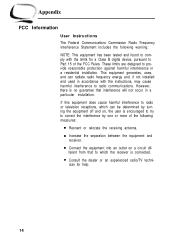
... will not occur in a particular installation. cian for a Class B digital device, pursuant to correct the interference by turning the equipment off and on a circuit dif- Appendix FCC Information User Instructions The Federal Communications Commission Radio Frequency Interference Statement includes the following measures: l Reorient or relocate the receiving antenna. This equipment generates, uses, and can be determined by...
... will not occur in a particular installation. cian for a Class B digital device, pursuant to correct the interference by turning the equipment off and on a circuit dif- Appendix FCC Information User Instructions The Federal Communications Commission Radio Frequency Interference Statement includes the following measures: l Reorient or relocate the receiving antenna. This equipment generates, uses, and can be determined by...
Owners Instructions
Page 17
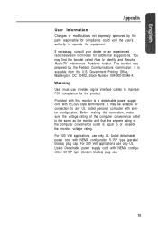
... making the connection, make sure the voltage rating of the computer convenience outlet is the same as the monitor and that the ampere rating of the computer convenience outlet is available from the U.S. It is equal to Identify and Resolve Radio/TV Interference Problems helpful. Provided with this monitor is a detachable power supply cord with NEMA configuration 6015P type (tandem blades) plug cap...
... making the connection, make sure the voltage rating of the computer convenience outlet is the same as the monitor and that the ampere rating of the computer convenience outlet is available from the U.S. It is equal to Identify and Resolve Radio/TV Interference Problems helpful. Provided with this monitor is a detachable power supply cord with NEMA configuration 6015P type (tandem blades) plug cap...
Owners Instructions
Page 18
...-003. MPR II Compliance The SyncMaster 700s monitor complies with these directives implies conformity to the standards set by the Voluntary Control Council For Interference by the Commission of the European Community. European Notice Manufacturer: Samsung Electronics Co., Ltd. Compliance with SWEDAC (MPR II) recommendations for correct handling. Product Safety 16 When used in a residential area or...
...-003. MPR II Compliance The SyncMaster 700s monitor complies with these directives implies conformity to the standards set by the Voluntary Control Council For Interference by the Commission of the European Community. European Notice Manufacturer: Samsung Electronics Co., Ltd. Compliance with SWEDAC (MPR II) recommendations for correct handling. Product Safety 16 When used in a residential area or...
Owners Instructions
Page 19
... monitor to a computer 5 Contrast 3, 6 D Degauss 9 Display modes timing chart 13 E European notice 16 F FCC information 14 Front panel 3 Function control buttons 3 G Geometric distortion 8 I IC compliance notice 16 Installation 5 M Macintosh 5 Manual ii MPR II compliance 16 P Paralleolgram 8 Pin assignments 13 Pincushion 8 Position 7 Power button 3 Power cable ii Power indicator 3 Power port 4 Powersaver 10 Preset mode 7 R Rear panel 4 Recall 9 S Safety Signal cable Signal port Size Specifications Stand T Tilt Trapzoid Troubleshooting...
... monitor to a computer 5 Contrast 3, 6 D Degauss 9 Display modes timing chart 13 E European notice 16 F FCC information 14 Front panel 3 Function control buttons 3 G Geometric distortion 8 I IC compliance notice 16 Installation 5 M Macintosh 5 Manual ii MPR II compliance 16 P Paralleolgram 8 Pin assignments 13 Pincushion 8 Position 7 Power button 3 Power cable ii Power indicator 3 Power port 4 Powersaver 10 Preset mode 7 R Rear panel 4 Recall 9 S Safety Signal cable Signal port Size Specifications Stand T Tilt Trapzoid Troubleshooting...


