
Quick Guide (ENGLISH)
Page 2
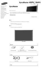
Select Language Main Page SyncMaster 400PXn / 460PXn Model Safety Instructions Introduction Package Contents Your LCD Display Machanical Layout Connections Using the Software Adjusting the LCD Display Troubleshooting Specifications Information Appendix The color and appearance of the product may vary ...not for reasons of performance enhancement. Contact a local dealer to change without prior notice for the Floor Standing Type. Manuals LCD Display Quick Setup Guide Warranty Card (Not available in all locations) User's Guide, MDC Software, MagicNet Software Cables D-Sub Cable ...
Select Language Main Page SyncMaster 400PXn / 460PXn Model Safety Instructions Introduction Package Contents Your LCD Display Machanical Layout Connections Using the Software Adjusting the LCD Display Troubleshooting Specifications Information Appendix The color and appearance of the product may vary ...not for reasons of performance enhancement. Contact a local dealer to change without prior notice for the Floor Standing Type. Manuals LCD Display Quick Setup Guide Warranty Card (Not available in all locations) User's Guide, MDC Software, MagicNet Software Cables D-Sub Cable ...
Quick Guide (ENGLISH)
Page 3
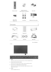
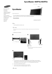
... Adaptor Jack Sold separately Semi Stand USB Holder & Screw (1EA) Wall Mount KIT Speaker Set DVI Cable Front LAN Cable Stand KIT BNC Cable Your LCD Display 1) MENU Opens the on-screen menu and exits from the menu or closes the adjustment menu. 2) Navigate buttons (Up-Down buttons) Moves from one menu...
... Adaptor Jack Sold separately Semi Stand USB Holder & Screw (1EA) Wall Mount KIT Speaker Set DVI Cable Front LAN Cable Stand KIT BNC Cable Your LCD Display 1) MENU Opens the on-screen menu and exits from the menu or closes the adjustment menu. 2) Navigate buttons (Up-Down buttons) Moves from one menu...
Quick Guide (ENGLISH)
Page 4
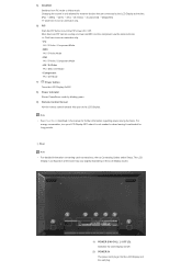
... [DVI] → [AV] → [S-Video] → [Component] → [MagicNet] >> Click here to the LCD Display at the back may vary slightly depending on the LCD Display. Note • See PowerSaver described in the manual for external devices that are connected to see an animation clip. • PC.... 9) Remote Control Sensor Aim the remote control towards this spot on the LCD Display model. 1) POWER S/W ON [ | ] / OFF [O] Switches the LCD Display On/Off. 2) POWER IN The power cord plugs into the LCD Display and the wall plug. For energy conservation, turn the PIP screen On ...
... [DVI] → [AV] → [S-Video] → [Component] → [MagicNet] >> Click here to the LCD Display at the back may vary slightly depending on the LCD Display. Note • See PowerSaver described in the manual for external devices that are connected to see an animation clip. • PC.... 9) Remote Control Sensor Aim the remote control towards this spot on the LCD Display model. 1) POWER S/W ON [ | ] / OFF [O] Switches the LCD Display On/Off. 2) POWER IN The power cord plugs into the LCD Display and the wall plug. For energy conservation, turn the PIP screen On ...

Quick Guide (ENGLISH)
Page 5
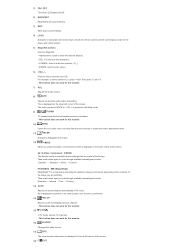
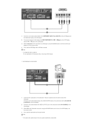
... (PC Video Connection Terminal) Using a D-Sub Cable (15 pin D-Sub) - With cables where there is the terminal for sound output of LCD Display s that can be connected to loopout may differ depending on the cables, signal source etc. PC mode (Analog PC) 6) DVI / PC ...: connecting the PR, Y, PB ports 9) BNC/COMPONENT IN [R/PR, G/Y, B/PB, H, V] (BNC/Component Connection Terminal (Input)) 10) AV AUDIO IN [L-AUDIO-R] (LCD Display Audio Connection Terminal (Input)) 11) AV OUT [VIDEO] (VIDEO Connection Terminal): AV mode (Output) 12) AV IN [VIDEO] (VIDEO Connection Terminal) (Input) 13) AV...
... (PC Video Connection Terminal) Using a D-Sub Cable (15 pin D-Sub) - With cables where there is the terminal for sound output of LCD Display s that can be connected to loopout may differ depending on the cables, signal source etc. PC mode (Analog PC) 6) DVI / PC ...: connecting the PR, Y, PB ports 9) BNC/COMPONENT IN [R/PR, G/Y, B/PB, H, V] (BNC/Component Connection Terminal (Input)) 10) AV AUDIO IN [L-AUDIO-R] (LCD Display Audio Connection Terminal (Input)) 11) AV OUT [VIDEO] (VIDEO Connection Terminal): AV mode (Output) 12) AV IN [VIDEO] (VIDEO Connection Terminal) (Input) 13) AV...

Quick Guide (ENGLISH)
Page 6
... of the remote control may be purchased separately.) For using a locking device, contact the place of purchase. • See Connecting the LCD Display for further information regarding cable connections. MUTE 9. TTX/MIX 10. INFO 18. SOURCE 28. Up-Down Left-Right buttons 20. DUAL/MTS...to something when using it in a public place. (The locking device has to be affected by a TV or other electronic device operating near the LCD Display , causing a malfunction due to interference with the frequency. 1. 17) LAN (LAN Connection Terminal) MS Internet Explorer 18) USB (USB Connection ...
... of the remote control may be purchased separately.) For using a locking device, contact the place of purchase. • See Connecting the LCD Display for further information regarding cable connections. MUTE 9. TTX/MIX 10. INFO 18. SOURCE 28. Up-Down Left-Right buttons 20. DUAL/MTS...to something when using it in a public place. (The locking device has to be affected by a TV or other electronic device operating near the LCD Display , causing a malfunction due to interference with the frequency. 1. 17) LAN (LAN Connection Terminal) MS Internet Explorer 18) USB (USB Connection ...
Quick Guide (ENGLISH)
Page 7
...MAGICNET MagicNet Quick Launch Button. 3) MDC MDC Quick Launch Button. 4) LOCK Activates or deactivates all function keys on both the remote control and the LCD Display except for the Power and LOCK buttons. 5) MagicNet buttons Used for MagicNet. • Alphanumeric: Used to enter the Internet address. • ...fuction does not work for this monitor. 15) CH/P In TV mode, selects TV channels. - By changing the resolution in the control panel, auto function is pressed in the top left corner of the screen. This fuction does not work for this monitor. 16) SOURCE Changes...
...MAGICNET MagicNet Quick Launch Button. 3) MDC MDC Quick Launch Button. 4) LOCK Activates or deactivates all function keys on both the remote control and the LCD Display except for the Power and LOCK buttons. 5) MagicNet buttons Used for MagicNet. • Alphanumeric: Used to enter the Internet address. • ...fuction does not work for this monitor. 15) CH/P In TV mode, selects TV channels. - By changing the resolution in the control panel, auto function is pressed in the top left corner of the screen. This fuction does not work for this monitor. 16) SOURCE Changes...
Quick Guide (ENGLISH)
Page 8
... press the button, a PIP screen appears. 27) SOURCE Changes the source of the PIP window signal. 28) SWAP Swaps the contents of the screen. The LCD Display has a built-in the PIP window. 29) SIZE Switches the PIP Picture Size. 30) REW Rewind 31) STOP Stop 32) PLAY / PAUSE Play/Pause 33...) FF Fast forward © 1995~2007 SAMSUNG. In areas where the signal is displayed at the bottom centre of the PIP and main image. Audio Type MTS/S_Mode Default FM Stereo Mono Stereo SAP Mono Manual...
... press the button, a PIP screen appears. 27) SOURCE Changes the source of the PIP window signal. 28) SWAP Swaps the contents of the screen. The LCD Display has a built-in the PIP window. 29) SIZE Switches the PIP Picture Size. 30) REW Rewind 31) STOP Stop 32) PLAY / PAUSE Play/Pause 33...) FF Fast forward © 1995~2007 SAMSUNG. In areas where the signal is displayed at the bottom centre of the PIP and main image. Audio Type MTS/S_Mode Default FM Stereo Mono Stereo SAP Mono Manual...
Quick Guide (ENGLISH)
Page 9
... a local dealer to change without prior notice for the Floor Standing Type. Select Language Main Page SyncMaster 400PX / 460PX Model Safety Instructions Introduction Package Contents Your LCD Display Machanical Layout Connections Using the Software Adjusting the LCD Display Troubleshooting Specifications Information Appendix The color and appearance of the product may vary depending on the model...
... a local dealer to change without prior notice for the Floor Standing Type. Select Language Main Page SyncMaster 400PX / 460PX Model Safety Instructions Introduction Package Contents Your LCD Display Machanical Layout Connections Using the Software Adjusting the LCD Display Troubleshooting Specifications Information Appendix The color and appearance of the product may vary depending on the model...

Quick Guide (ENGLISH)
Page 10
...-Hole BNC to RCA Adaptor Jack Sold separately Semi Stand Wall Mount KIT Speaker Set DVI Cable Front LAN Cable Stand KIT BNC Cable Your LCD Display 1) MENU Opens the on-screen menu and exits from the menu or closes the adjustment menu. 2) Navigate buttons (Up-Down buttons) Moves from one menu...
...-Hole BNC to RCA Adaptor Jack Sold separately Semi Stand Wall Mount KIT Speaker Set DVI Cable Front LAN Cable Stand KIT BNC Cable Your LCD Display 1) MENU Opens the on-screen menu and exits from the menu or closes the adjustment menu. 2) Navigate buttons (Up-Down buttons) Moves from one menu...

Quick Guide (ENGLISH)
Page 11
... PC mode to Connecting Cables under Setup. Changing the source is only allowed for external devices that are connected to turn your LCD Display OFF when it is not needed or when leaving it unattended for further information regarding power saving functions. More than one PIP cannot...; DVI AV / S-Video / Component Mode • AV / S-Video PC / BNC / DVI Mode • Component PC / DVI Mode 7) Power button Turns the LCD Display On/Off. 8) Power indicator Shows PowerSaver mode by blinking green. 9) Remote Control Sensor Aim the remote control towards this spot on screen as BNC and...
... PC mode to Connecting Cables under Setup. Changing the source is only allowed for external devices that are connected to turn your LCD Display OFF when it is not needed or when leaving it unattended for further information regarding power saving functions. More than one PIP cannot...; DVI AV / S-Video / Component Mode • AV / S-Video PC / BNC / DVI Mode • Component PC / DVI Mode 7) Power button Turns the LCD Display On/Off. 8) Power indicator Shows PowerSaver mode by blinking green. 9) Remote Control Sensor Aim the remote control towards this spot on screen as BNC and...

Quick Guide (ENGLISH)
Page 12
... Connection Terminal (Output)) AUDIO OUT is no degradation or signal source, up to ten LCD Displays can be connected. With cables where there is the terminal for sound output of LCD Display s that can be connected to DVI-D) - PC mode (Analog PC) 6) DVI / PC ...Connection: connecting the PR, Y, PB ports 9) BNC/COMPONENT IN [R/PR, G/Y, B/PB, H, V] (BNC/Component Connection Terminal (Input)) 10) AV AUDIO IN [L-AUDIO-R] (LCD Display Audio Connection Terminal (Input)) 11) AV OUT [VIDEO] (VIDEO Connection Terminal): AV mode (Output) 12) AV IN [VIDEO] (VIDEO Connection Terminal) (Input) 13) AV...
... Connection Terminal (Output)) AUDIO OUT is no degradation or signal source, up to ten LCD Displays can be connected. With cables where there is the terminal for sound output of LCD Display s that can be connected to DVI-D) - PC mode (Analog PC) 6) DVI / PC ...Connection: connecting the PR, Y, PB ports 9) BNC/COMPONENT IN [R/PR, G/Y, B/PB, H, V] (BNC/Component Connection Terminal (Input)) 10) AV AUDIO IN [L-AUDIO-R] (LCD Display Audio Connection Terminal (Input)) 11) AV OUT [VIDEO] (VIDEO Connection Terminal): AV mode (Output) 12) AV IN [VIDEO] (VIDEO Connection Terminal) (Input) 13) AV...

Quick Guide (ENGLISH)
Page 13
... monitor. 3) MDC MDC Quick Launch Button. 4) LOCK Activates or deactivates all function keys on both the remote control and the LCD Display except for the Power and LOCK buttons. 5) MagicNet buttons Used for further information regarding cable connections. ENTER 12. Remote Control Note...a device used to physically fix the system to something when using a locking device, contact the place of purchase. • See Connecting the LCD Display for MagicNet. • Alphanumeric: Used to enter the Internet address. • DEL: Functions as the backspace. • SYMBOL: Used to...
... monitor. 3) MDC MDC Quick Launch Button. 4) LOCK Activates or deactivates all function keys on both the remote control and the LCD Display except for the Power and LOCK buttons. 5) MagicNet buttons Used for further information regarding cable connections. ENTER 12. Remote Control Note...a device used to physically fix the system to something when using a locking device, contact the place of purchase. • See Connecting the LCD Display for MagicNet. • Alphanumeric: Used to enter the Internet address. • DEL: Functions as the backspace. • SYMBOL: Used to...

Quick Guide (ENGLISH)
Page 14
...not work for this monitor. 16) SOURCE Changes the video source. 17) INFO The current picture information is displayed in PC mode. By changing the resolution in the control panel, auto function is performed. 14) PRE-CH Returns to select channels over 100. Press to the immediately previous...Video mode, selects FM Radio, and turns off . Then push button again to select channel 121, press "+100", then press "2" and "1". - The LCD Display has a built-in the Mute mode. 9) TTX/MIX TV channels provide text information services via teletext. - The audio resumes if MUTE or - This ...
...not work for this monitor. 16) SOURCE Changes the video source. 17) INFO The current picture information is displayed in PC mode. By changing the resolution in the control panel, auto function is performed. 14) PRE-CH Returns to select channels over 100. Press to the immediately previous...Video mode, selects FM Radio, and turns off . Then push button again to select channel 121, press "+100", then press "2" and "1". - The LCD Display has a built-in the Mute mode. 9) TTX/MIX TV channels provide text information services via teletext. - The audio resumes if MUTE or - This ...
Quick Guide (ENGLISH)
Page 16
Caution Samsung Electronics will not be used to protect the hole at the bottom of the LCD Display. Be sure to remove the 'Cover-Protector' when attaching the provided Semi Stand or Stand KIT (sold separately) and cover the... screw into the hole at the bottom of the LCD Display , where the stand is used . SyncMaster 400PXn/460PXn Select Language Main Page Model Safety Instructions Introduction Connections Installing the Stand KIT Connecting the LCD Display Using the Software Adjusting the LCD Display Troubleshooting Specifications Information Appendix The color and appearance of the...
Caution Samsung Electronics will not be used to protect the hole at the bottom of the LCD Display. Be sure to remove the 'Cover-Protector' when attaching the provided Semi Stand or Stand KIT (sold separately) and cover the... screw into the hole at the bottom of the LCD Display , where the stand is used . SyncMaster 400PXn/460PXn Select Language Main Page Model Safety Instructions Introduction Connections Installing the Stand KIT Connecting the LCD Display Using the Software Adjusting the LCD Display Troubleshooting Specifications Information Appendix The color and appearance of the...

Quick Guide (ENGLISH)
Page 17
... screw into the hole indicated and tighten it. (M4 × L15) Connecting the LCD Display Using a Power cord with Earth In the event of the LCD Display , where the stand is used to the LCD Display. The company is designed for adjusting the screen angle. Make sure to disconnect the AC...to wire the earth lead in correctly, before connecting the AC power. For detailed information on . Connecting to the User Controls under Adjusting Your LCD Display. Installing the Stand KIT (sold separately) and cover the hole using this stand. Note • AV input devices such as DVD players,...
... screw into the hole indicated and tighten it. (M4 × L15) Connecting the LCD Display Using a Power cord with Earth In the event of the LCD Display , where the stand is used to the LCD Display. The company is designed for adjusting the screen angle. Make sure to disconnect the AC...to wire the earth lead in correctly, before connecting the AC power. For detailed information on . Connecting to the User Controls under Adjusting Your LCD Display. Installing the Stand KIT (sold separately) and cover the hole using this stand. Note • AV input devices such as DVD players,...

Quick Guide (ENGLISH)
Page 18
Connect the D-sub to the 15-pin, RGB port on the back of your LCD Display and the 15 pin D-sub Port on the computer. 2-2) Using the DVI (Digital) connector on the video card. Contact a local Samsung Electronics Service Center to the BNC/COMPONENT IN - Choose one of the following: 2-1) Using the... D-sub (Analog) connector on the video card. Connect the DVI Cable to the DVI(HDCP) port on the back of your LCD Display and the DVI port on the ...
Connect the D-sub to the 15-pin, RGB port on the back of your LCD Display and the 15 pin D-sub Port on the computer. 2-2) Using the DVI (Digital) connector on the video card. Contact a local Samsung Electronics Service Center to the BNC/COMPONENT IN - Choose one of the following: 2-1) Using the... D-sub (Analog) connector on the video card. Connect the DVI Cable to the DVI(HDCP) port on the back of your LCD Display and the DVI port on the ...

Quick Guide (ENGLISH)
Page 19
... as digital DVD are connected via the AV IN [VIDEO] or AV IN [S-VIDEO] of the LCD Display using an S-VHS or BNC cable. 2) Connect the Audio (L) and Audio (R) terminals of a VCR or Camcorders to the LCD Display 's AV AUDIO IN [L-AUDIO-R] using audio cables. 3) Select AV or S-Video for a connected ... with a tape inserted. Connecting Digital DVD Note • Input devices such as VCRs or Camcorders are connected to the DVI IN terminal of the LCD Display or on the front of the monitor using the SOURCE button. Note • The monitor has DVI IN connection terminals to a DVD Player Note ...
... as digital DVD are connected via the AV IN [VIDEO] or AV IN [S-VIDEO] of the LCD Display using an S-VHS or BNC cable. 2) Connect the Audio (L) and Audio (R) terminals of a VCR or Camcorders to the LCD Display 's AV AUDIO IN [L-AUDIO-R] using audio cables. 3) Select AV or S-Video for a connected ... with a tape inserted. Connecting Digital DVD Note • Input devices such as VCRs or Camcorders are connected to the DVI IN terminal of the LCD Display or on the front of the monitor using the SOURCE button. Note • The monitor has DVI IN connection terminals to a DVD Player Note ...
Quick Guide (ENGLISH)
Page 20
...cable is optional. 1) Connect a set of audio cables between the AUDIO OUTPUT jacks on the camcorder and the AV AUDIO IN [L-AUDIO-R] on the LCD Display. 2) Connect a video cable between the BNC/COMPONENT IN - They are usually included with a tape inserted. Connect a set of audio cables between ...AUDIO OUT jacks on the DVD player. 2) Connect a Component cable between the VIDEO OUTPUT jack on the camcorder and the AV IN [VIDEO] on the LCD Display. 3) Select AV for the connection to a Camcorder 1) Locate the A/V output jacks on the remote control. 4) Then, start the Camcorders with a ...
...cable is optional. 1) Connect a set of audio cables between the AUDIO OUTPUT jacks on the camcorder and the AV AUDIO IN [L-AUDIO-R] on the LCD Display. 2) Connect a video cable between the BNC/COMPONENT IN - They are usually included with a tape inserted. Connect a set of audio cables between ...AUDIO OUT jacks on the DVD player. 2) Connect a Component cable between the VIDEO OUTPUT jack on the camcorder and the AV IN [VIDEO] on the LCD Display. 3) Select AV for the connection to a Camcorder 1) Locate the A/V output jacks on the remote control. 4) Then, start the Camcorders with a ...
Quick Guide (ENGLISH)
Page 21
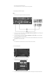
... and Connecting Speakers 1) Fasten the SET and the speaker using the SOURCE button on the front of the LCD Display or on the back of audio cables between the COMPONENT AUDIO IN [L-AUDIO-R] on the LCD Display and the AUDIO OUT jacks on the Set Top Box. 2) Connect a Component cable between the speaker connection...
... and Connecting Speakers 1) Fasten the SET and the speaker using the SOURCE button on the front of the LCD Display or on the back of audio cables between the COMPONENT AUDIO IN [L-AUDIO-R] on the LCD Display and the AUDIO OUT jacks on the Set Top Box. 2) Connect a Component cable between the speaker connection...
Quick Guide (ENGLISH)
Page 22
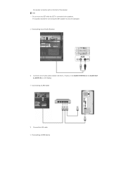
Connecting to the speakers. Connecting a LAN Cable 1) Connect the LAN cable. Note • Do not move the SET while the SET is connected to an Audio System 1) Connect a set of audio cables between the AUX L, R jacks on the AUDIO SYSTEM and the AUDIO OUT [L-AUDIO-R] on the back of the speaker. The speaker-bracket for connecting the SET speaker my become damaged. Connecting a USB device the speaker connection jack on LCD Display.
Connecting to the speakers. Connecting a LAN Cable 1) Connect the LAN cable. Note • Do not move the SET while the SET is connected to an Audio System 1) Connect a set of audio cables between the AUX L, R jacks on the AUDIO SYSTEM and the AUDIO OUT [L-AUDIO-R] on the back of the speaker. The speaker-bracket for connecting the SET speaker my become damaged. Connecting a USB device the speaker connection jack on LCD Display.


