User Manual
Page 1
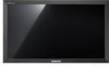
SyncMaster 320TSn-3 LCD Display User Manual The color and the appearance may differ depending on the product, and the specifications are subject to change without prior notice to improve the performance.
SyncMaster 320TSn-3 LCD Display User Manual The color and the appearance may differ depending on the product, and the specifications are subject to change without prior notice to improve the performance.

User Manual
Page 5
... may peel off the indication labels on the product. When cleaning the product, do not spray water directly onto the main body of the TFT-LCD screen, wipe with a slightly moistened, soft cloth. When cleaning the product, make sure to be repaired, contact a Service Center. Clean Others Safety Instructions When cleaning...
... may peel off the indication labels on the product. When cleaning the product, do not spray water directly onto the main body of the TFT-LCD screen, wipe with a slightly moistened, soft cloth. When cleaning the product, make sure to be repaired, contact a Service Center. Clean Others Safety Instructions When cleaning...
User Manual
Page 10
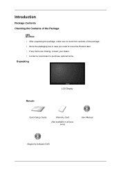
Introduction Package Contents Checking the Contents of the Package Note • After unpacking the package, make sure to check the contents of the package. • Store the packaging box in case you need to move the Product later. • If any items are missing, contact your dealer. • Contact a local dealer to purchase optional items. Unpacking Manuals LCD Display Quick Setup Guide Warranty Card (Not available in all locations) User Manual MagicInfo Software DVD
Introduction Package Contents Checking the Contents of the Package Note • After unpacking the package, make sure to check the contents of the package. • Store the packaging box in case you need to move the Product later. • If any items are missing, contact your dealer. • Contact a local dealer to purchase optional items. Unpacking Manuals LCD Display Quick Setup Guide Warranty Card (Not available in all locations) User Manual MagicInfo Software DVD
User Manual
Page 12
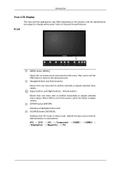
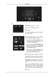
... item. Selects the input source that an external device is not on -screen menu and exits from PC mode to the previous menu. Introduction Your LCD Display The color and the appearance may differ depending on the product, and the specifications are subject to change without prior notice to . [PC DVI AV...
... item. Selects the input source that an external device is not on -screen menu and exits from PC mode to the previous menu. Introduction Your LCD Display The color and the appearance may differ depending on the product, and the specifications are subject to change without prior notice to . [PC DVI AV...

User Manual
Page 13
... the PIP button to turn your LCD Display OFF when it is not needed or when leaving it unattended for turning the LCD Display on the LCD Display. Power button [ ] Use this spot on and off. Power indicator Shows PowerSaver mode by Samsung and connect the MagicInfo output on ...[HDMI IN 2 (MAGICINFO)] on the network box to use MagicInfo with RGB (PC) and Component signals. The LCD Display's configuration at the back may display abnormally if the connected external input signal is enabled. Brightness Sensor Automatically detects the surrounding brightness. Note See the "Connections...
... the PIP button to turn your LCD Display OFF when it is not needed or when leaving it unattended for turning the LCD Display on the LCD Display. Power button [ ] Use this spot on and off. Power indicator Shows PowerSaver mode by Samsung and connect the MagicInfo output on ...[HDMI IN 2 (MAGICINFO)] on the network box to use MagicInfo with RGB (PC) and Component signals. The LCD Display's configuration at the back may display abnormally if the connected external input signal is enabled. Brightness Sensor Automatically detects the surrounding brightness. Note See the "Connections...
User Manual
Page 14
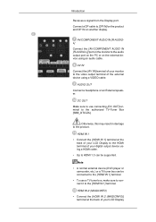
... the [RGB/COMPONENT IN] port on the monitor to the BNC port on the PC using the DVI cable. Introduction POWER S/W ON [ ] / OFF Switches the LCD Display On/Off. DVI IN (PC Video Connection Terminal) Connect the [DVI IN] port on the monitor to BNC cable. DP IN POWER The power cord... plugs into the LCD Display and the wall outlet. RGB/DVI/DP/HDMI AUDIO IN (PC/DVI/ DP/HDMI Audio Connection Terminal (Input)) Connect the [RGB/DVI/DP/HDMI AUDIO...
... the [RGB/COMPONENT IN] port on the monitor to the BNC port on the PC using the DVI cable. Introduction POWER S/W ON [ ] / OFF Switches the LCD Display On/Off. DVI IN (PC Video Connection Terminal) Connect the [DVI IN] port on the monitor to BNC cable. DP IN POWER The power cord... plugs into the LCD Display and the wall outlet. RGB/DVI/DP/HDMI AUDIO IN (PC/DVI/ DP/HDMI Audio Connection Terminal (Input)) Connect the [RGB/DVI/DP/HDMI AUDIO...
User Manual
Page 15
... an External speaker. HDMI IN 2 (MAGICINFO) • Connect the [HDMI IN 2 (MAGICINFO)] terminal at the back of your LCD Display to the HDMI terminal of your LCD Display Connect a DP cable to the authorized TV-Tuner Box [SBB_DTC/ZA]. DC OUT Make sure to use a TV tuner box, make...output terminal of your digital output device using a VIDEO cable. Introduction Receives a signal from the Display port. AV/COMPONENT AUDIO IN [R-AUDIOL] Connect the [AV/COMPONENT AUDIO IN [R-AUDIO-L]] port on another display. Note • A normal external device (DVD player or camcorder, etc.) or a TV ...
... an External speaker. HDMI IN 2 (MAGICINFO) • Connect the [HDMI IN 2 (MAGICINFO)] terminal at the back of your LCD Display to the HDMI terminal of your LCD Display Connect a DP cable to the authorized TV-Tuner Box [SBB_DTC/ZA]. DC OUT Make sure to use a TV tuner box, make...output terminal of your digital output device using a VIDEO cable. Introduction Receives a signal from the Display port. AV/COMPONENT AUDIO IN [R-AUDIOL] Connect the [AV/COMPONENT AUDIO IN [R-AUDIO-L]] port on another display. Note • A normal external device (DVD player or camcorder, etc.) or a TV ...

User Manual
Page 18
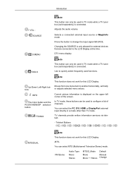
Electronic Program Guide (EPG) display. Turns the product Off. Used to enter the password during the OSD adjustment or to select Digital channels. SOURCE D.MENU TOOLS Up-Down Left-Right ... with the frequency. Introduction Remote Control Note The performance of the remote control may be affected by a TV or other electronic device operating near the LCD Display , causing a malfunction due to change the channel.
Electronic Program Guide (EPG) display. Turns the product Off. Used to enter the password during the OSD adjustment or to select Digital channels. SOURCE D.MENU TOOLS Up-Down Left-Right ... with the frequency. Introduction Remote Control Note The performance of the remote control may be affected by a TV or other electronic device operating near the LCD Display , causing a malfunction due to change the channel.
User Manual
Page 19
Note This function does not work for this LCD Display. You can select the PC, DVI, HDMI or DisplayPort external input directly ...Teletext Buttons MTS/DUAL Note This function does not work for external devices that are connected to the LCD Display at the time. MTS- Use to change the input signal SOURCE. You can select MTS (Multichannel Television ...Stereo) mode. Changing the SOURCE is displayed on the upper left corner of channels. Introduction + VOL SOURCE D.MENU TOOLS Up-Down Left-Right buttons...
Note This function does not work for this LCD Display. You can select the PC, DVI, HDMI or DisplayPort external input directly ...Teletext Buttons MTS/DUAL Note This function does not work for external devices that are connected to the LCD Display at the time. MTS- Use to change the input signal SOURCE. You can select MTS (Multichannel Television ...Stereo) mode. Changing the SOURCE is displayed on the upper left corner of channels. Introduction + VOL SOURCE D.MENU TOOLS Up-Down Left-Right buttons...
User Manual
Page 23
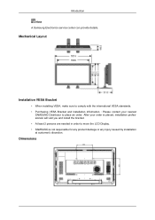
... service center can provide details. After your nearest SAMSUNG Distributor to move the LCD Display. • SAMSUNG is placed, installation professionals will visit you and install the bracket. • At least 2 persons are needed in order to place an order. Mechanical Layout ...
... service center can provide details. After your nearest SAMSUNG Distributor to move the LCD Display. • SAMSUNG is placed, installation professionals will visit you and install the bracket. • At least 2 persons are needed in order to place an order. Mechanical Layout ...
User Manual
Page 26
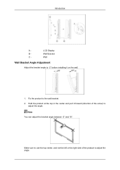
Wall Bracket C - Wall Wall Bracket Angle Adjustment Adjust the bracket angle to the wall bracket. 2. Make sure to use the top center, and not the left or the right side of the arrow) to adjust the angle. Fix the product to -2° before installing it forward (direction of the product to adjust the angle. Note You can adjust the bracket angle between -2° and 15°. Introduction A - Hold the product at the top in the center and pull it on the wall. 1. LCD Display B -
Wall Bracket C - Wall Wall Bracket Angle Adjustment Adjust the bracket angle to the wall bracket. 2. Make sure to use the top center, and not the left or the right side of the arrow) to adjust the angle. Fix the product to -2° before installing it forward (direction of the product to adjust the angle. Note You can adjust the bracket angle between -2° and 15°. Introduction A - Hold the product at the top in the center and pull it on the wall. 1. LCD Display B -
User Manual
Page 37
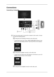
Choose one from the following options. Using the D-sub (Analog) connector on the video card. • Connect the D-sub to the 15-pin, [RGB/COMPONENT IN] port on the back of your LCD Display and the 15 pin D-sub Port on the computer. Using the DVI (Digital) connector on the video card. • Connect the DVI Cable to the monitor. Using the D-sub (Digital) connector on the video card. Connections Connecting a Computer There are several ways to connect the computer to the [DVI IN] port on the back of your LCD Display and the DVI port on the computer.
Choose one from the following options. Using the D-sub (Analog) connector on the video card. • Connect the D-sub to the 15-pin, [RGB/COMPONENT IN] port on the back of your LCD Display and the 15 pin D-sub Port on the computer. Using the DVI (Digital) connector on the video card. • Connect the DVI Cable to the monitor. Using the D-sub (Digital) connector on the video card. Connections Connecting a Computer There are several ways to connect the computer to the [DVI IN] port on the back of your LCD Display and the DVI port on the computer.

User Manual
Page 38
...HDMI1 must be selected before PC is selected, be connected to the POWER port on the back of the LCD Display. Turn on the power switch. Note Contact a local SAMSUNG Electronics Service Center to buy optional items. Connecting to Other devices Note • AV input devices such as... DVD players, VCRs or camcorders as well as an input source when connected to the contents under Adjusting Your LCD Display. • The LCD Display 's configuration at ...
...HDMI1 must be selected before PC is selected, be connected to the POWER port on the back of the LCD Display. Turn on the power switch. Note Contact a local SAMSUNG Electronics Service Center to buy optional items. Connecting to Other devices Note • AV input devices such as... DVD players, VCRs or camcorders as well as an input source when connected to the contents under Adjusting Your LCD Display. • The LCD Display 's configuration at ...
User Manual
Page 39
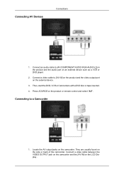
... between the VIDEO OUTPUT jack on the camcorder and the [AV IN] on the product or remote control and select "AV". Press SOURCE on the LCD Display . Then, start the DVD, VCR or Camcorders with a DVD disc or tape inserted. 4. Connect an audio cable to [AV/COMPONENT AUDIO IN [R-AUDIO-L]] on the...
... between the VIDEO OUTPUT jack on the camcorder and the [AV IN] on the product or remote control and select "AV". Press SOURCE on the LCD Display . Then, start the DVD, VCR or Camcorders with a DVD disc or tape inserted. 4. Connect an audio cable to [AV/COMPONENT AUDIO IN [R-AUDIO-L]] on the...
User Manual
Page 40
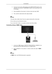
... Using a HDMI Cable 1. Connect a set of audio cables between the AUDIO OUTPUT jacks on the camcorder and the [AV /COMPONENT AUDIO IN [R-AUDIO-L]] on the LCD Display . 3. Press SOURCE on the product or remote control and select "HDMI1 / HDMI2" Note In HDMI mode, only PCM format audio is stereo, you need to...
... Using a HDMI Cable 1. Connect a set of audio cables between the AUDIO OUTPUT jacks on the camcorder and the [AV /COMPONENT AUDIO IN [R-AUDIO-L]] on the LCD Display . 3. Press SOURCE on the product or remote control and select "HDMI1 / HDMI2" Note In HDMI mode, only PCM format audio is stereo, you need to...
User Manual
Page 41
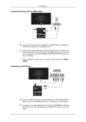
... product or remote control and select "HDMI1 / HDMI2" Connecting a DVD Player Connect a RGB to Component cable between the [AV/COMPONENT AUDIO IN [R-AUDIO-L]] on the LCD Display and the AUDIO OUT jacks on the DVD player. Connections Connecting Using a DVI to HDMI Cable Connect a DVI-HDMI cable to [HDMI IN 2 (MAGICINFO)] or..., and connect the opposite jack to the [RGB/DVI/DP/HDMI AUDIO IN] terminal of audio cables between the [RGB/COMPONENT IN] port on the LCD Display and the PR, Y, PB jacks on the digital device.
... product or remote control and select "HDMI1 / HDMI2" Connecting a DVD Player Connect a RGB to Component cable between the [AV/COMPONENT AUDIO IN [R-AUDIO-L]] on the LCD Display and the AUDIO OUT jacks on the DVD player. Connections Connecting Using a DVI to HDMI Cable Connect a DVI-HDMI cable to [HDMI IN 2 (MAGICINFO)] or..., and connect the opposite jack to the [RGB/DVI/DP/HDMI AUDIO IN] terminal of audio cables between the [RGB/COMPONENT IN] port on the LCD Display and the PR, Y, PB jacks on the digital device.
User Manual
Page 42
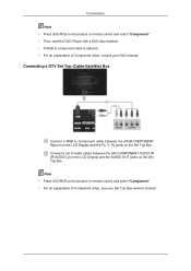
...manual. Note • Press SOURCE on the Set Top Box. Connect a set of audio cables between the [AV/COMPONENT AUDIO IN [R-AUDIO-L]] on the LCD Display and the AUDIO OUT jacks on the product or remote control and select "Component". • Then, start the DVD Player with a DVD disc inserted.... • A RGB to Component cable between the [RGB/COMPONENT IN] port on the LCD Display and the PR, Y, PB jacks on the product or remote control and select "Component". • For an explanation of Component video, consult your Set Top...
...manual. Note • Press SOURCE on the Set Top Box. Connect a set of audio cables between the [AV/COMPONENT AUDIO IN [R-AUDIO-L]] on the LCD Display and the AUDIO OUT jacks on the product or remote control and select "Component". • Then, start the DVD Player with a DVD disc inserted.... • A RGB to Component cable between the [RGB/COMPONENT IN] port on the LCD Display and the PR, Y, PB jacks on the product or remote control and select "Component". • For an explanation of Component video, consult your Set Top...
User Manual
Page 43
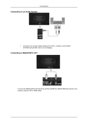
Connecting to MAGICINFO OUT Connect the [MAGICINFO OUT] terminal and the [HDMI IN 2 (MAGICINFO)] terminal on LCD Display. Connect a set of audio cables between the AUX L, R jacks on the AUDIO SYSTEM and [AUDIO OUT] on the product using the DP to an Audio System 1. Connections Connecting to HDMI cable.
Connecting to MAGICINFO OUT Connect the [MAGICINFO OUT] terminal and the [HDMI IN 2 (MAGICINFO)] terminal on LCD Display. Connect a set of audio cables between the AUX L, R jacks on the AUDIO SYSTEM and [AUDIO OUT] on the product using the DP to an Audio System 1. Connections Connecting to HDMI cable.
User Manual
Page 62
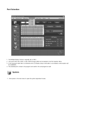
The Multiple Display Control is not selected, communication will be selected in the program and used , COM1 through COM4 can be unavailable. 4. If the exact port name that is connected to the LCD Display using a serial cable is originally set to open the system adjustment screen. System 1. If any port other than COM1 is stored in the Port Selection Menu. 3. The selected port is used for the next program as well. Port Selection 1. Click System in the main menu to COM1. 2.
The Multiple Display Control is not selected, communication will be selected in the program and used , COM1 through COM4 can be unavailable. 4. If the exact port name that is connected to the LCD Display using a serial cable is originally set to open the system adjustment screen. System 1. If any port other than COM1 is stored in the Port Selection Menu. 3. The selected port is used for the next program as well. Port Selection 1. Click System in the main menu to COM1. 2.
User Manual
Page 71
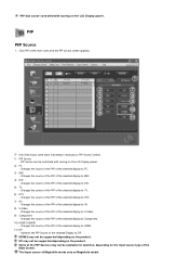
... Sources may not be controlled with turning on MagicInfo model. Some of the selected display to AV. 8) S-Video - PIP Source can be available for selection, depending on the LCD Display power. The Input source of the selected display to DVI. 5) TV - Changes the source of the PIP of MagicInfo works... only on the LCD Display power. 2) PC - Switches the PIP Source of the selected display to DP. Changes the source of the PIP of the selected Display to Component. 10) HDMI1/HDMI2 - Changes the source of the PIP of the ...
... Sources may not be controlled with turning on MagicInfo model. Some of the selected display to AV. 8) S-Video - PIP Source can be available for selection, depending on the LCD Display power. The Input source of the selected display to DVI. 5) TV - Changes the source of the PIP of MagicInfo works... only on the LCD Display power. 2) PC - Switches the PIP Source of the selected display to DP. Changes the source of the PIP of the selected Display to Component. 10) HDMI1/HDMI2 - Changes the source of the PIP of the ...


