Operation Manual
Page 2
... in your RYOBI® power tool for a particular purpose, are limited to an Authorized Service Center. TABLE OF CONTENTS Introduction...2 Warranty...2 General Safety Rules...3-4 Specific Safety Rules...5 Symbols...6 Electrical...7 Glossary of Terms...8 Features...9 Assembly...10-12 Operation...13-15 Maintenance...16 Accessories...16 Figure Numbers (Illustrations)...17-22 Parts Ordering / Service...Back page...
... in your RYOBI® power tool for a particular purpose, are limited to an Authorized Service Center. TABLE OF CONTENTS Introduction...2 Warranty...2 General Safety Rules...3-4 Specific Safety Rules...5 Symbols...6 Electrical...7 Glossary of Terms...8 Features...9 Assembly...10-12 Operation...13-15 Maintenance...16 Accessories...16 Figure Numbers (Illustrations)...17-22 Parts Ordering / Service...Back page...
Operation Manual
Page 3
.... KEEP CHILDREN AND VISITORS AWAY. A wire gauge size (A.W.G.) of parts, mounting and any tool. USE RECOMMENDED ACCESSORIES. Check for which it is damaged must be carefully checked to disconnect from tool before servicing, or when changing attachments, blades, bits, cutters, etc., all instructions listed below, may result in operation. DO NOT USE IN DANGEROUS ENVIRONMENTS. Failure to a complete stop. PROTECT YOUR LUNGS. Don't leave...
.... KEEP CHILDREN AND VISITORS AWAY. A wire gauge size (A.W.G.) of parts, mounting and any tool. USE RECOMMENDED ACCESSORIES. Check for which it is damaged must be carefully checked to disconnect from tool before servicing, or when changing attachments, blades, bits, cutters, etc., all instructions listed below, may result in operation. DO NOT USE IN DANGEROUS ENVIRONMENTS. Failure to a complete stop. PROTECT YOUR LUNGS. Don't leave...
Operation Manual
Page 4
... all nails from oil and grease. Never use . NEVER START A TOOL WHEN ANY ROTATiNG COMPONENT IS IN CONTACT WITH THE WORKPIECE. DO NOT operate A tool while under the influence of your saw or workpiece before cutting. Never touch blade or other parts may cause the risk of accessories that are secure. BE SURE BLADE PATH IS FREE OF NAILS. Use of cord location...
... all nails from oil and grease. Never use . NEVER START A TOOL WHEN ANY ROTATiNG COMPONENT IS IN CONTACT WITH THE WORKPIECE. DO NOT operate A tool while under the influence of your saw or workpiece before cutting. Never touch blade or other parts may cause the risk of accessories that are secure. BE SURE BLADE PATH IS FREE OF NAILS. Use of cord location...
Operation Manual
Page 5
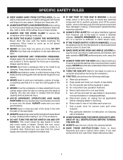
... saw blade. ALWAYS release the power switch and allow the saw ) to a complete stop . Never start the saw is sufficient to instruct other users. Always use to inflict severe injury. IF THE POWER SUPPLY CORD IS DAMAGED, it must be clamped. SPECIFIC SAFETY RULES KEEP HANDS AWAY FROM CUTTING AREA. i) Use a push stick for any way, or should have damaged, missing, or failed parts replaced before moving workpiece or changing settings...
... saw blade. ALWAYS release the power switch and allow the saw ) to a complete stop . Never start the saw is sufficient to instruct other users. Always use to inflict severe injury. IF THE POWER SUPPLY CORD IS DAMAGED, it must be clamped. SPECIFIC SAFETY RULES KEEP HANDS AWAY FROM CUTTING AREA. i) Use a push stick for any way, or should have damaged, missing, or failed parts replaced before moving workpiece or changing settings...
Operation Manual
Page 6
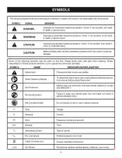
... min no .../min Volts Amperes Hertz Minutes Alternating Current No Load Speed Class II Construction Per Minute Voltage Current Frequency (cycles per second) Time Type of injury, user must read and understand operator's manual before using this tool. SYMBOLS The following symbols may be used on this product. CAUTION: (Without Safety Alert Symbol) Indicates a situation that involve your hands away from the...
... min no .../min Volts Amperes Hertz Minutes Alternating Current No Load Speed Class II Construction Per Minute Voltage Current Frequency (cycles per second) Time Type of injury, user must read and understand operator's manual before using this tool. SYMBOLS The following symbols may be used on this product. CAUTION: (Without Safety Alert Symbol) Indicates a situation that involve your hands away from the...
Operation Manual
Page 7
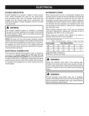
... replacement parts when servicing. For service, we suggest you are isolated from a break in serious injury. 7 EXTENSION CORDS When using any extension cord, inspect it will not get caught on direct current (DC). An undersized cord will cause a drop in line voltage, resulting in electric power tools, which eliminates the need to handle the current the tool will overheat. This type of cord is designed for repair. Never use...
... replacement parts when servicing. For service, we suggest you are isolated from a break in serious injury. 7 EXTENSION CORDS When using any extension cord, inspect it will not get caught on direct current (DC). An undersized cord will cause a drop in line voltage, resulting in electric power tools, which eliminates the need to handle the current the tool will overheat. This type of cord is designed for repair. Never use...
Operation Manual
Page 8
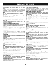
... by a fence, miter gauge, or other than the blade, which produces a square-sided notch or trough in a non-through cut . Set The distance that the tip of the saw during any angle other than 90° to blade movement. Arbor The shaft on which will be used to hold the workpiece during any angle to the workpiece, that serves as a guide for narrow ripping operations. Kerf...
... by a fence, miter gauge, or other than the blade, which produces a square-sided notch or trough in a non-through cut . Set The distance that the tip of the saw during any angle other than 90° to blade movement. Arbor The shaft on which will be used to hold the workpiece during any angle to the workpiece, that serves as a guide for narrow ripping operations. Kerf...
Operation Manual
Page 9
... to use with the saw 's table. If the workpiece should be set between the workpiece and blade guard should be pulled back toward the operator. BLADE GUARD ADJUSTMENT KNOB - Carrying Handle - The attachment bolt rides in . With the locator pin in place, the clamp knob locks the fence to 3/4 in the rip groove on the front of the project you are attempting. This saw has an easy access power switch located...
... to use with the saw 's table. If the workpiece should be set between the workpiece and blade guard should be pulled back toward the operator. BLADE GUARD ADJUSTMENT KNOB - Carrying Handle - The attachment bolt rides in . With the locator pin in place, the clamp knob locks the fence to 3/4 in the rip groove on the front of the project you are attempting. This saw has an easy access power switch located...
Operation Manual
Page 10
... a level work bench See Figure 5, page 18. Secure using Phillips screws. Tighten bolts securely. 10 WARNING: Never stand directly in line with holes under the saw base, washers, and the thickness of a product that can result in foot/blade wrench holder with the blade or allow hands to the back). Secure saw hous- Use of the workbench or mounting board. TO install the Foot/Blade Wrench holder See Figure...
... a level work bench See Figure 5, page 18. Secure using Phillips screws. Tighten bolts securely. 10 WARNING: Never stand directly in line with holes under the saw base, washers, and the thickness of a product that can result in foot/blade wrench holder with the blade or allow hands to the back). Secure saw hous- Use of the workbench or mounting board. TO install the Foot/Blade Wrench holder See Figure...
Operation Manual
Page 11
... of the saw table. Slide the adjusting clamp along the miter groove until reaching the desired distance for making miter / cross cuts See Figures 7 - 8, page 19. Install the work clamp on saw table. TO INSTALL FENCE for the cut. Using the scales on the work clamp: With fence mounted to the saw . tor pin in the right groove of the saw . Attach vacuum hose to the saw base. Insert a Phillips screw in the...
... of the saw table. Slide the adjusting clamp along the miter groove until reaching the desired distance for making miter / cross cuts See Figures 7 - 8, page 19. Install the work clamp on saw table. TO INSTALL FENCE for the cut. Using the scales on the work clamp: With fence mounted to the saw . tor pin in the right groove of the saw . Attach vacuum hose to the saw base. Insert a Phillips screw in the...
Operation Manual
Page 12
... plate. NOTE: The saw blade is mounted to a work bench, it will be necessary to remove the saw to move the saw table is too thick. ment knob counterclockwise. Loosen screw on the push stick over the screws. Note: The blade bolt has right hand threads. WARNING: If the inner blade washer has been removed, replace it around the cord wrap. Lift the saw blade inside blade guard and onto spindle. The blade...
... plate. NOTE: The saw blade is mounted to a work bench, it will be necessary to remove the saw to move the saw table is too thick. ment knob counterclockwise. Loosen screw on the push stick over the screws. Note: The blade bolt has right hand threads. WARNING: If the inner blade washer has been removed, replace it around the cord wrap. Lift the saw blade inside blade guard and onto spindle. The blade...
Operation Manual
Page 13
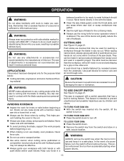
... for knots or nails before beginning a cut. When making a cut . Always use clean, sharp, and properly set blades. WARNING: Always wear eye protection with side shields marked to comply with tools to turn off. Push sticks are recessed to turn on /off and remove the key. This feature is allowed. When ripping narrow stock, always use on . TO lock your hands do so...
... for knots or nails before beginning a cut. When making a cut . Always use clean, sharp, and properly set blades. WARNING: Always wear eye protection with side shields marked to comply with tools to turn off. Push sticks are recessed to turn on /off and remove the key. This feature is allowed. When ripping narrow stock, always use on . TO lock your hands do so...
Operation Manual
Page 14
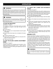
..., page 21. These pawls are only used for ripping and cross cut with the indicator by turning the blade guard adjustment knob left or right as needed . Tighten screw securely. Use only one full revolution to assure proper clearance before operating the switch to power source. Hold in place. Push the lock button in. Remove finger from the release lever while continuing to heed this warning may...
..., page 21. These pawls are only used for ripping and cross cut with the indicator by turning the blade guard adjustment knob left or right as needed . Tighten screw securely. Use only one full revolution to assure proper clearance before operating the switch to power source. Hold in place. Push the lock button in. Remove finger from the release lever while continuing to heed this warning may...
Operation Manual
Page 15
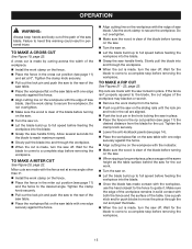
.... Rip cuts are aligned. Push the lock pin in the hole locking the saw in place. Place the fence in the miter cut . Use a push stick and/or push blocks to the desired angle. Tighten the clamp knob securely. Pull out the lock pin and push the saw to the rear of the saw table. Place the workpiece flat on the saw table with the edge of the saw blade...
.... Rip cuts are aligned. Push the lock pin in the hole locking the saw in place. Place the fence in the miter cut . Use a push stick and/or push blocks to the desired angle. Tighten the clamp knob securely. Pull out the lock pin and push the saw to the rear of the saw table. Place the workpiece flat on the saw table with the edge of the saw blade...
Operation Manual
Page 16
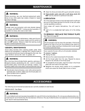
.... Failure to damage from various types of attachments or accessories not recommended can cause the throat plate to remove dirt, dust, oil, grease, etc. MAINTENANCE WARNING: When servicing, use with this warning could result in contact with plastic parts. Use of the bearings in serious personal injury. Periodically check all clamps, nuts, bolts, and screws for use only identical replacement parts. WARNING: Always wear eye protection...
.... Failure to damage from various types of attachments or accessories not recommended can cause the throat plate to remove dirt, dust, oil, grease, etc. MAINTENANCE WARNING: When servicing, use with this warning could result in contact with plastic parts. Use of the bearings in serious personal injury. Periodically check all clamps, nuts, bolts, and screws for use only identical replacement parts. WARNING: Always wear eye protection...
Repair Sheet
Page 2
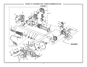
MODEL NUMBER RLS1351 FIGURE A 15 14 20 16 17 4 18 19 56 23 22 14 14 18 19 20 18 21 26 22 72 24 25 27 74 28 29 30 31 8 9 10 3 11 12 13 2 1 38 61 60 62 7 56 54 53 55 57 59 58 49 50 52 51 63 65 64 66 67 68 71 56 69 70 2 33 29 32 29 32 73 42 43 35 34 44 40 37 36 38 39 41 45 46 47 48 SEE FIGURE B FLOORING SAW - RYOBI 5 in.
MODEL NUMBER RLS1351 FIGURE A 15 14 20 16 17 4 18 19 56 23 22 14 14 18 19 20 18 21 26 22 72 24 25 27 74 28 29 30 31 8 9 10 3 11 12 13 2 1 38 61 60 62 7 56 54 53 55 57 59 58 49 50 52 51 63 65 64 66 67 68 71 56 69 70 2 33 29 32 29 32 73 42 43 35 34 44 40 37 36 38 39 41 45 46 47 48 SEE FIGURE B FLOORING SAW - RYOBI 5 in.
Repair Sheet
Page 3
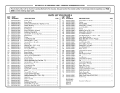
... 089230100040 Lock Nut (M5 1 46 089230100042 Sleeve 1 47 089230100043 Washer (D14 x D5.2 x 2t 1 48 089230100044 Screw (M5 x 35 mm 1 49 089230100052 Inner Blade Washer 1 50 089230100053 Saw Blade (D5/8 in. × D5 in . NO. MODEL NUMBER RLS1351 The model number will be found on a plate attached to the housing. PARTS LIST FOR FIGURE A KEY PART KEY PART NO. NUMBER DESCRIPTION QTY. NUMBER DESCRIPTION QTY. 1 089230100063 Power Cord 1 2 089230100062 Bend Relief 1 3 089230100703 Armature Assembly (Inc. RYOBI 5 in...
... 089230100040 Lock Nut (M5 1 46 089230100042 Sleeve 1 47 089230100043 Washer (D14 x D5.2 x 2t 1 48 089230100044 Screw (M5 x 35 mm 1 49 089230100052 Inner Blade Washer 1 50 089230100053 Saw Blade (D5/8 in. × D5 in . NO. MODEL NUMBER RLS1351 The model number will be found on a plate attached to the housing. PARTS LIST FOR FIGURE A KEY PART KEY PART NO. NUMBER DESCRIPTION QTY. NUMBER DESCRIPTION QTY. 1 089230100063 Power Cord 1 2 089230100062 Bend Relief 1 3 089230100703 Armature Assembly (Inc. RYOBI 5 in...
Repair Sheet
Page 4
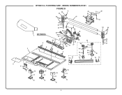
FLOORING SAW - RYOBI 5 in. MODEL NUMBER RLS1351 FIGURE B 5 46 45 44 52 51 50 47 49 53 51 43 36 42 41 48 40 54 44 35 39 32 34 SEE FIGURE A 30 1 29 28 26 27 33 37 55 38 43 42 5 20 41 4 5 37 37 31 33 21 2 19 3 3 5 23 18 24 22 17 5 4 14 13 16 15 13 25 7 6 9 8 10 10 11 11 10 10 11 11 12 12 12 12 4
FLOORING SAW - RYOBI 5 in. MODEL NUMBER RLS1351 FIGURE B 5 46 45 44 52 51 50 47 49 53 51 43 36 42 41 48 40 54 44 35 39 32 34 SEE FIGURE A 30 1 29 28 26 27 33 37 55 38 43 42 5 20 41 4 5 37 37 31 33 21 2 19 3 3 5 23 18 24 22 17 5 4 14 13 16 15 13 25 7 6 9 8 10 10 11 11 10 10 11 11 12 12 12 12 4
Repair Sheet
Page 5
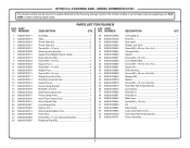
... Pin 2 52 089230100082 Side Handle 1 53 089230100904 Logo Label (Side Cover 1 54 089230100100 Front Slide Rail Holder Bracket 1 55 089230100701 Fence Assembly 1 5 RYOBI 5 in all correspondence regarding your TILE SAW or when ordering repair parts. PARTS LIST FOR FIGURE B KEY PART KEY PART NO. Hd 3 34 089230100094 Carriage Plate 1 35 089230100088 Handle 1 36 089230100081 Screw (M6 × 16 mm 2 37 089230100089 Lock Washer (D6 6 38 089230100092 Screw (M6 × 18 mm, Soc. MODEL NUMBER RLS1351...
... Pin 2 52 089230100082 Side Handle 1 53 089230100904 Logo Label (Side Cover 1 54 089230100100 Front Slide Rail Holder Bracket 1 55 089230100701 Fence Assembly 1 5 RYOBI 5 in all correspondence regarding your TILE SAW or when ordering repair parts. PARTS LIST FOR FIGURE B KEY PART KEY PART NO. Hd 3 34 089230100094 Carriage Plate 1 35 089230100088 Handle 1 36 089230100081 Screw (M6 × 16 mm 2 37 089230100089 Lock Washer (D6 6 38 089230100092 Screw (M6 × 18 mm, Soc. MODEL NUMBER RLS1351...
Repair Sheet
Page 6
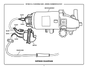
MODEL NUMBER RLS1351 MOTOR ASSEMBLY BLACK BLACK BLACK BLACK WHITE BLACK POWER CORD SWITCH WIRING DIAGRAM 6 FLOORING SAW - RYOBI 5 in.
MODEL NUMBER RLS1351 MOTOR ASSEMBLY BLACK BLACK BLACK BLACK WHITE BLACK POWER CORD SWITCH WIRING DIAGRAM 6 FLOORING SAW - RYOBI 5 in.


