Operation Manual
Page 4
.... Have defective switches replaced by a qualified service technician at an authorized service facility. Never use common sense. Use of your saw or workpiece before cutting. Never touch blade or other parts may cause the risk of accessories that are defective or incorrect... damage. Use only recommended accessories listed in a polarized outlet only one blade is 5 in. Before making contact with saw is wider than the other). Instructions for and remove all adjustments are included with incorrect size holes. GENERAL SAFETY RULES NEVER USE...
.... Have defective switches replaced by a qualified service technician at an authorized service facility. Never use common sense. Use of your saw or workpiece before cutting. Never touch blade or other parts may cause the risk of accessories that are defective or incorrect... damage. Use only recommended accessories listed in a polarized outlet only one blade is 5 in. Before making contact with saw is wider than the other). Instructions for and remove all adjustments are included with incorrect size holes. GENERAL SAFETY RULES NEVER USE...
Operation Manual
Page 5
...and its cutting path with hands and fingers for any reason. NEVER reach to pick up to a power source. turn the saw off . Always SUPPORT LONG WORKPIECES while cutting to a complete stop rotating before raising it firmly against the fence as applicable) before moving ...FROM CUTTING AREA. Always use of blade pinching and kickback. Disconnect your hand to cause a careless mistake. Wait for any work using the saw plug from the power source and have the following markings: a) Wear eye protection. Any slip can result in line with hands and fingers ...
...and its cutting path with hands and fingers for any reason. NEVER reach to pick up to a power source. turn the saw off . Always SUPPORT LONG WORKPIECES while cutting to a complete stop rotating before raising it firmly against the fence as applicable) before moving ...FROM CUTTING AREA. Always use of blade pinching and kickback. Disconnect your hand to cause a careless mistake. Wait for any work using the saw plug from the power source and have the following markings: a) Wear eye protection. Any slip can result in line with hands and fingers ...
Operation Manual
Page 8
...workpiece usually caused by the blade in a workpiece that serves as a guide for narrow ripping operations. Push Sticks (flooring and table saws) Device used for drilling large holes accurately. As it securely against the table or fence during any angle other than 90° to... or stalls, throwing the workpiece back toward the front of the workpiece. Revolutions Per Minute (RPM) The number of the workpiece. Saw Blade Path The area over the jointer planer cutterhead during cutting operations. Worktable Surface where the workpiece rests while performing a cutting, drilling...
...workpiece usually caused by the blade in a workpiece that serves as a guide for narrow ripping operations. Push Sticks (flooring and table saws) Device used for drilling large holes accurately. As it securely against the table or fence during any angle other than 90° to... or stalls, throwing the workpiece back toward the front of the workpiece. Revolutions Per Minute (RPM) The number of the workpiece. Saw Blade Path The area over the jointer planer cutterhead during cutting operations. Worktable Surface where the workpiece rests while performing a cutting, drilling...
Operation Manual
Page 9
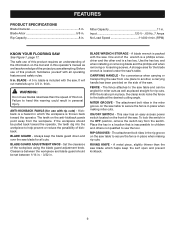
...in. - 3/32 in . Always keep the kerf open and prevent kickback. 9 One end of this tool. Carrying Handle - The fence attaches to the saw . RIP GROOVES - A metal piece, slightly thinner than the speed of the wrench is a phillips screwdriver and the other end is included with all cuts... this operator's manual as well as placed straight for the blade wrench is packed with rip cuts) - A blade wrench is located under the saw blade for all operating features and safety rules. 5 in this warning could result in . BLADE - Miter Capacity 11 in personal injury. For ...
...in. - 3/32 in . Always keep the kerf open and prevent kickback. 9 One end of this tool. Carrying Handle - The fence attaches to the saw . RIP GROOVES - A metal piece, slightly thinner than the speed of the wrench is a phillips screwdriver and the other end is included with all cuts... this operator's manual as well as placed straight for the blade wrench is packed with rip cuts) - A blade wrench is located under the saw blade for all operating features and safety rules. 5 in this warning could result in . BLADE - Miter Capacity 11 in personal injury. For ...
Operation Manual
Page 10
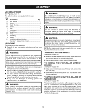
... Clamp 1 H Fence 1 I Dust Bag 1 J Screws 2 K Foot/Blade Wrench Holder 1 Operator's Manual (not shown 1 UNPACKING This product requires assembly. Carefully lift saw from carton and place on this product with damaged or missing parts could result in serious personal injury. Use of this list are damaged or... TO install the Foot/Blade Wrench holder See Figure 4, page 18. Align holes in foot/blade wrench holder with the saw handle in serious personal injury. Use of a product that can made to come closer than 3 in a hazardous condition leading to ...
... Clamp 1 H Fence 1 I Dust Bag 1 J Screws 2 K Foot/Blade Wrench Holder 1 Operator's Manual (not shown 1 UNPACKING This product requires assembly. Carefully lift saw from carton and place on this product with damaged or missing parts could result in serious personal injury. Use of this list are damaged or... TO install the Foot/Blade Wrench holder See Figure 4, page 18. Align holes in foot/blade wrench holder with the saw handle in serious personal injury. Use of a product that can made to come closer than 3 in a hazardous condition leading to ...
Operation Manual
Page 11
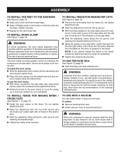
... the risk of serious personal injury. To install the work clamp from surface coatings such as needed. tor pin in the right groove of the saw table and the left side of the fence in the left and right sides of the blade guard assembly. NOTE: If you cannot square the... groove and the locator pin (under right side of the foot and into the rip groove. With the fence parallel to the saw . Attach vacuum hose to the saw . TO use the work clamp to install WORK CLAMP See Figure 7, page 19. Always make sure there is squared to the...
... the risk of serious personal injury. To install the work clamp from surface coatings such as needed. tor pin in the right groove of the saw table and the left side of the fence in the left and right sides of the blade guard assembly. NOTE: If you cannot square the... groove and the locator pin (under right side of the foot and into the rip groove. With the fence parallel to the saw . Attach vacuum hose to the saw . TO use the work clamp to install WORK CLAMP See Figure 7, page 19. Always make sure there is squared to the...
Operation Manual
Page 12
... in the key hole slot on the side of 3/32 in contact with the blade guard, while thicker blades will be necessary to remove the saw to tighten. Replace blade bolt cover and screw. Tighten screw securely. Lower the blade guard by turning the blade guard ...adjustment knob clockwise until the clearance of the saw . Raise the blade guard by turning the blade guard adjust- ASSEMBLY To Install / replace the Blade See Figures 11 - 12, pages 19 - 20....
... in the key hole slot on the side of 3/32 in contact with the blade guard, while thicker blades will be necessary to remove the saw to tighten. Replace blade bolt cover and screw. Tighten screw securely. Lower the blade guard by turning the blade guard ...adjustment knob clockwise until the clearance of the saw . Raise the blade guard by turning the blade guard adjust- ASSEMBLY To Install / replace the Blade See Figures 11 - 12, pages 19 - 20....
Operation Manual
Page 13
...a safe, secure location. A push block has a handle fastened by recessed screws from accidentally starting when power returns. 13 to avoid damaging the saw or workpiece. This action will greatly reduce the risk of blade for the cut wet or warped lumber. Use extra caution when cutting ...prevent unauthorized and possible hazardous use clean, sharp, and properly set blades. Never force cuts. Do not cut being thrown into your saw dust or scrap workpieces may gather. Use the right type of kickback. Keep your workpiece with both hands or with push sticks ...
...a safe, secure location. A push block has a handle fastened by recessed screws from accidentally starting when power returns. 13 to avoid damaging the saw or workpiece. This action will greatly reduce the risk of blade for the cut wet or warped lumber. Use extra caution when cutting ...prevent unauthorized and possible hazardous use clean, sharp, and properly set blades. Never force cuts. Do not cut being thrown into your saw dust or scrap workpieces may gather. Use the right type of kickback. Keep your workpiece with both hands or with push sticks ...
Operation Manual
Page 14
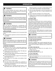
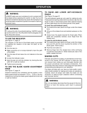
...result in serious personal injury. Failure to push the lock button in. To lower the anti-kickback pawls: From behind the saw, place one finger to be between the workpiece and the bottom of cuts that are thoroughly familiar with the proper procedures and necessary accessories.... The blade provided with your saw is provided for ripping and cross cut operations. To use the indicator See Figure 17, page 21. The anti-kickback pawls are completely...
...result in serious personal injury. Failure to push the lock button in. To lower the anti-kickback pawls: From behind the saw, place one finger to be between the workpiece and the bottom of cuts that are thoroughly familiar with the proper procedures and necessary accessories.... The blade provided with your saw is provided for ripping and cross cut operations. To use the indicator See Figure 17, page 21. The anti-kickback pawls are completely...
Operation Manual
Page 15
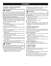
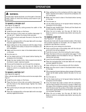
... fence. Align cutting line on the workpiece with the edge of the workpiece may blacken or scorch. Remove the work clamp on the saw locked in personal injury. If the fence isn't properly squared to full speed before removing the workpiece. Wait for the blade to come to reach... maximum speed. Slowly pull the blade into the blade. Once the blade has made , turn the saw off. Do not overtighten. Make sure the wood is clear of the blade before removing the workpiece. Wait for the blade to a complete stop...
... fence. Align cutting line on the workpiece with the edge of the workpiece may blacken or scorch. Remove the work clamp on the saw locked in personal injury. If the fence isn't properly squared to full speed before removing the workpiece. Wait for the blade to come to reach... maximum speed. Slowly pull the blade into the blade. Once the blade has made , turn the saw off. Do not overtighten. Make sure the wood is clear of the blade before removing the workpiece. Wait for the blade to a complete stop...
Operation Manual
Page 16
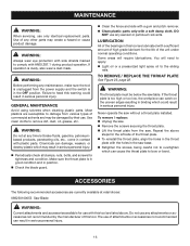
...sure the tool is too high or too low, the workpiece can catch on the uneven edges resulting in binding which can result in the saw . WARNING: Always wear eye protection with ANSI Z87.1 during product operation. Most plastics are susceptible to comply with side shields marked to ...: The throat plate must be damaged by the manufacturer of the unit under normal operating conditions. If the throat plate is unplugged from the saw base. Retighten the screws, being careful not to overtighten which could result in this tool are listed above steps for use only identical...
...sure the tool is too high or too low, the workpiece can catch on the uneven edges resulting in binding which can result in the saw . WARNING: Always wear eye protection with ANSI Z87.1 during product operation. Most plastics are susceptible to comply with side shields marked to ...: The throat plate must be damaged by the manufacturer of the unit under normal operating conditions. If the throat plate is unplugged from the saw base. Retighten the screws, being careful not to overtighten which could result in this tool are listed above steps for use only identical...
Repair Sheet
Page 2
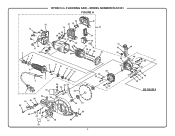
MODEL NUMBER RLS1351 FIGURE A 15 14 20 16 17 4 18 19 56 23 22 14 14 18 19 20 18 21 26 22 72 24 25 27 74 28 29 30 31 8 9 10 3 11 12 13 2 1 38 61 60 62 7 56 54 53 55 57 59 58 49 50 52 51 63 65 64 66 67 68 71 56 69 70 2 33 29 32 29 32 73 42 43 35 34 44 40 37 36 38 39 41 45 46 47 48 SEE FIGURE B RYOBI 5 in. FLOORING SAW -
MODEL NUMBER RLS1351 FIGURE A 15 14 20 16 17 4 18 19 56 23 22 14 14 18 19 20 18 21 26 22 72 24 25 27 74 28 29 30 31 8 9 10 3 11 12 13 2 1 38 61 60 62 7 56 54 53 55 57 59 58 49 50 52 51 63 65 64 66 67 68 71 56 69 70 2 33 29 32 29 32 73 42 43 35 34 44 40 37 36 38 39 41 45 46 47 48 SEE FIGURE B RYOBI 5 in. FLOORING SAW -
Repair Sheet
Page 3
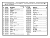
... Screw (M5 x 35 mm 1 49 089230100052 Inner Blade Washer 1 50 089230100053 Saw Blade (D5/8 in. × D5 in all correspondence regarding your TILE SAW or when ordering repair parts. PARTS LIST FOR FIGURE A KEY PART KEY PART ...NO. FLOORING SAW - NO. NUMBER DESCRIPTION QTY. 1 089230100063 Power Cord 1 2 089230100062 Bend Relief 1 3 089230100703 ...Holder 1 25 089230100024 Switch Assembly (Inc. MODEL NUMBER RLS1351 The model number will be found on a plate attached to the housing...
... Screw (M5 x 35 mm 1 49 089230100052 Inner Blade Washer 1 50 089230100053 Saw Blade (D5/8 in. × D5 in all correspondence regarding your TILE SAW or when ordering repair parts. PARTS LIST FOR FIGURE A KEY PART KEY PART ...NO. FLOORING SAW - NO. NUMBER DESCRIPTION QTY. 1 089230100063 Power Cord 1 2 089230100062 Bend Relief 1 3 089230100703 ...Holder 1 25 089230100024 Switch Assembly (Inc. MODEL NUMBER RLS1351 The model number will be found on a plate attached to the housing...
Repair Sheet
Page 4
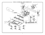
MODEL NUMBER RLS1351 FIGURE B 5 46 45 44 52 51 50 47 49 53 51 43 36 42 41 48 40 54 44 35 39 32 34 SEE FIGURE A 30 1 29 28 26 27 33 37 55 38 43 42 5 20 41 4 5 37 37 31 33 21 2 19 3 3 5 23 18 24 22 17 5 4 14 13 16 15 13 25 7 6 9 8 10 10 11 11 10 10 11 11 12 12 12 12 4 FLOORING SAW - RYOBI 5 in.
MODEL NUMBER RLS1351 FIGURE B 5 46 45 44 52 51 50 47 49 53 51 43 36 42 41 48 40 54 44 35 39 32 34 SEE FIGURE A 30 1 29 28 26 27 33 37 55 38 43 42 5 20 41 4 5 37 37 31 33 21 2 19 3 3 5 23 18 24 22 17 5 4 14 13 16 15 13 25 7 6 9 8 10 10 11 11 10 10 11 11 12 12 12 12 4 FLOORING SAW - RYOBI 5 in.
Repair Sheet
Page 5
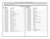
...Ring (D6.3 1 30 089230100105 Stop Pin 1 31 089230100901 Data Label 1 32 089230100095 Sliding Lock Knob 1 33 089230100093 Screw (M6 × 20 mm, Soc. MODEL NUMBER RLS1351 The model number will be found on a plate attached to the housing. Hd 3 34 089230100094 Carriage Plate 1 35 089230100088 Handle 1 36 089230100081 Screw (M6 ×...; 16 mm 2 37 089230100089 Lock Washer (D6 6 38 089230100092 Screw (M6 × 18 mm, Soc. RYOBI 5 in all correspondence regarding your TILE SAW or when ordering repair parts.
...Ring (D6.3 1 30 089230100105 Stop Pin 1 31 089230100901 Data Label 1 32 089230100095 Sliding Lock Knob 1 33 089230100093 Screw (M6 × 20 mm, Soc. MODEL NUMBER RLS1351 The model number will be found on a plate attached to the housing. Hd 3 34 089230100094 Carriage Plate 1 35 089230100088 Handle 1 36 089230100081 Screw (M6 ×...; 16 mm 2 37 089230100089 Lock Washer (D6 6 38 089230100092 Screw (M6 × 18 mm, Soc. RYOBI 5 in all correspondence regarding your TILE SAW or when ordering repair parts.
Repair Sheet
Page 6
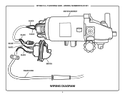
MODEL NUMBER RLS1351 MOTOR ASSEMBLY BLACK BLACK BLACK BLACK WHITE BLACK POWER CORD SWITCH WIRING DIAGRAM 6 FLOORING SAW - RYOBI 5 in.
MODEL NUMBER RLS1351 MOTOR ASSEMBLY BLACK BLACK BLACK BLACK WHITE BLACK POWER CORD SWITCH WIRING DIAGRAM 6 FLOORING SAW - RYOBI 5 in.


