
English Manual
Page 1
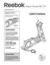
If you have questions, or if parts are damaged or missing, DO NOT CONTACT THE STORE; IMPORTANT: Please register this product (see the limited warranty on the back cover of this manual) ...
If you have questions, or if parts are damaged or missing, DO NOT CONTACT THE STORE; IMPORTANT: Please register this product (see the limited warranty on the back cover of this manual) ...
English Manual
Page 2
... 2 IMPORTANT PRECAUTIONS 3 BEFORE YOU BEGIN 4 PART IDENTIFICATION CHART 5 ASSEMBLY 6 HOW TO USE THE ELLIPTICAL 13 FCC INFORMATION 24 MAINTENANCE AND TROUBLESHOOTING 25 EXERCISE GUIDELINES 27 PART LIST 28 EXPLODED DRAWING 30 ORDERING REPLACEMENT PARTS Back Cover LIMITED WARRANTY Back Cover WARNING DECAL PLACEMENT This drawing shows the location(s) of Reebok. Note: The decal(s) may not...
... 2 IMPORTANT PRECAUTIONS 3 BEFORE YOU BEGIN 4 PART IDENTIFICATION CHART 5 ASSEMBLY 6 HOW TO USE THE ELLIPTICAL 13 FCC INFORMATION 24 MAINTENANCE AND TROUBLESHOOTING 25 EXERCISE GUIDELINES 27 PART LIST 28 EXPLODED DRAWING 30 ORDERING REPLACEMENT PARTS Back Cover LIMITED WARRANTY Back Cover WARNING DECAL PLACEMENT This drawing shows the location(s) of Reebok. Note: The decal(s) may not...
English Manual
Page 3
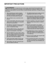
...arms when mounting, dismounting, or using the elliptical; Do not put the elliptical in a controlled way. 14. Various factors may result in general. 13. The elliptical does not have a freewheel; Before beginning any worn parts immediately. 8. To protect the floor or... or institutional setting. 5. Keep the elliptical indoors, away from the elliptical at least 3 ft. (0.9 m) of clearance in this manual and all warnings on your elliptical before using your elliptical. Inspect and properly tighten all parts regularly. Place the elliptical on a level surface, with pre-...
...arms when mounting, dismounting, or using the elliptical; Do not put the elliptical in a controlled way. 14. Various factors may result in general. 13. The elliptical does not have a freewheel; Before beginning any worn parts immediately. 8. To protect the floor or... or institutional setting. 5. Keep the elliptical indoors, away from the elliptical at least 3 ft. (0.9 m) of clearance in this manual and all warnings on your elliptical before using your elliptical. Inspect and properly tighten all parts regularly. Place the elliptical on a level surface, with pre-...
English Manual
Page 4
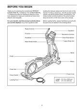
...Thank you have questions after Before reading further, please familiarize yourself with the parts that are shown on the front cover of this manual. Ramp Controls Console Handlebar Water Bottle Holder Speakers Resistance Controls Heart Rate Monitor Upper ...Body Arm Pedal Pedal Disc Power Switch Leveling Foot Ramp Wheel Power Cord Length: 6 ft. 8 in. (203 cm) Width: 2 ft. 3 in the drawing below. If you for selecting the revolutionary REEBOK® SUPER RAMP RL 7.0 elliptical...
...Thank you have questions after Before reading further, please familiarize yourself with the parts that are shown on the front cover of this manual. Ramp Controls Console Handlebar Water Bottle Holder Speakers Resistance Controls Heart Rate Monitor Upper ...Body Arm Pedal Pedal Disc Power Switch Leveling Foot Ramp Wheel Power Cord Length: 6 ft. 8 in. (203 cm) Width: 2 ft. 3 in the drawing below. If you for selecting the revolutionary REEBOK® SUPER RAMP RL 7.0 elliptical...
English Manual
Page 5
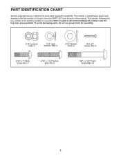
To avoid damaging parts, do not use power tools for assembly. 5/16" Locknut (106)–-4 5/16" Split Washer (105)–-5 5/16" Washer (104)–-2 #8 x 3/4" Screw (78)–-9 5/16" x 1" Patch ... (88)–-14 5 The number following the key number is the quantity needed for assembly. Note: If a part is the key number of the part, from the PART LIST near the end of this manual. PART IDENTIFICATION CHART See the drawings below each drawing is not in the hardware kit, check to identify the...
To avoid damaging parts, do not use power tools for assembly. 5/16" Locknut (106)–-4 5/16" Split Washer (105)–-5 5/16" Washer (104)–-2 #8 x 3/4" Screw (78)–-9 5/16" x 1" Patch ... (88)–-14 5 The number following the key number is the quantity needed for assembly. Note: If a part is the key number of the part, from the PART LIST near the end of this manual. PART IDENTIFICATION CHART See the drawings below each drawing is not in the hardware kit, check to identify the...
English Manual
Page 6
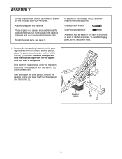
...two persons. Do not dispose of the packing materials until this step is completed. To identify small parts, see page 5. Hold the Front Stabilizer (2) under the front of the other person hold the elliptical to prevent it from the packing materials. Attach the Front Stabilizer with four 3/8" x 2 1/2"... remove the packing inserts and lower the Front Stabilizer (2) and the Frame (1). 2 Packing Inserts 88 88 6 In addition to assemble the elliptical, call 1-800-445-2480. With the help of the Frame (1) as shown. With the help of ratchet wrenches. Place all assembly steps...
...two persons. Do not dispose of the packing materials until this step is completed. To identify small parts, see page 5. Hold the Front Stabilizer (2) under the front of the other person hold the elliptical to prevent it from the packing materials. Attach the Front Stabilizer with four 3/8" x 2 1/2"... remove the packing inserts and lower the Front Stabilizer (2) and the Frame (1). 2 Packing Inserts 88 88 6 In addition to assemble the elliptical, call 1-800-445-2480. With the help of the Frame (1) as shown. With the help of ratchet wrenches. Place all assembly steps...
English Manual
Page 12
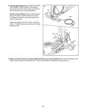
... 13 and plug in the reset position. See the upper drawing. Next, make sure that all parts are properly tightened before you use the elliptical. Place a mat beneath the elliptical to the lowest incline level. 12. The Ramp (4) will then move downward to protect the floor. 12 Attach the Upright (6) to the Frame (1) with... 105 133 6 4 1 105 81 13. Note: After assembly is in the Power Cord (133). Make sure that the Power Switch (37) is completed, some extra parts may be left over.
... 13 and plug in the reset position. See the upper drawing. Next, make sure that all parts are properly tightened before you use the elliptical. Place a mat beneath the elliptical to the lowest incline level. 12. The Ramp (4) will then move downward to protect the floor. 12 Attach the Upright (6) to the Frame (1) with... 105 133 6 4 1 105 81 13. Note: After assembly is in the Power Cord (133). Make sure that the Power Switch (37) is completed, some extra parts may be left over.

English Manual
Page 24
... can be determined by turning the equipment off and on, try to correct the interference by the party responsible for a Class B digital device, pursuant to part 15 of the following measures: •• Reorient or relocate the receiving antenna. •• Increase the separation between the equipment and the receiver. •...
... can be determined by turning the equipment off and on, try to correct the interference by the party responsible for a Class B digital device, pursuant to part 15 of the following measures: •• Reorient or relocate the receiving antenna. •• Increase the separation between the equipment and the receiver. •...
English Manual
Page 25
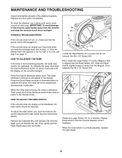
...the #8 x 1/2" Screw (91). Remove the indicated #8 x 3/4" Screws (78) from the Magnet. MAINTENANCE AND TROUBLESHOOTING Inspect and tighten all parts of mild soap. Press the Calorie Workouts button once. HOW TO ADJUST THE REED SWITCH If the console does not display correct feedback, the ...correct feedback. To clean the elliptical, use a damp cloth and a small amount of the elliptical regularly. Press the Quick Ramp increase or decrease button to the manual mode. HOW TO CALIBRATE THE RAMP If the ramp is not functioning properly, the ramp may need to the console, ...
...the #8 x 1/2" Screw (91). Remove the indicated #8 x 3/4" Screws (78) from the Magnet. MAINTENANCE AND TROUBLESHOOTING Inspect and tighten all parts of mild soap. Press the Calorie Workouts button once. HOW TO ADJUST THE REED SWITCH If the console does not display correct feedback, the ...correct feedback. To clean the elliptical, use a damp cloth and a small amount of the elliptical regularly. Press the Quick Ramp increase or decrease button to the manual mode. HOW TO CALIBRATE THE RAMP If the ramp is not functioning properly, the ramp may need to the console, ...

English Manual
Page 26
... and the left pedal disc are pedaling, even when the resistance is adjusted to the highest level, the drive belt may need to remove these parts. 78 78 128 78 118 57 39 38 When the Drive Belt (57) is tight, tighten the Pivot Screw (128). Then, reattach the left shield...
... and the left pedal disc are pedaling, even when the resistance is adjusted to the highest level, the drive belt may need to remove these parts. 78 78 128 78 118 57 39 38 When the Drive Belt (57) is tight, tighten the Pivot Screw (128). Then, reattach the left shield...
English Manual
Page 27
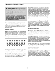
... exercise information, obtain a reputable book or consult your exercise program. Remember, proper nutrition and adequate rest are rounded off to make exercise a regular and enjoyable part of your exercise until your heart rate is to the nearest ten years). Burning Fat—-To burn fat effectively, you to 10 minutes of...
... exercise information, obtain a reputable book or consult your exercise program. Remember, proper nutrition and adequate rest are rounded off to make exercise a regular and enjoyable part of your exercise until your heart rate is to the nearest ten years). Burning Fat—-To burn fat effectively, you to 10 minutes of...
English Manual
Page 28
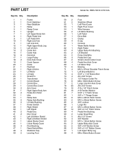
PART LIST Key No. Qty. 50 2 51 2 52 1 53 1 54 1 55 2 56 1 57 1 58 1 59 4 60 1 61 1 62 1 ...38 1 39 1 40 2 41 2 42 1 43 1 44 1 45 1 46 4 47 1 48 4 49 2 Description Frame Front Stabilizer Rear Stabilizer Ramp Ramp Cover Upright Left Upper Body Arm Right Pedal Arm Left Pedal Arm Right Link Arm Left Link Arm Right Upper Body Leg Left Lift Arm...Control Board Control Box Control Box Cover Arm Cover Right Upper Body Arm Pedal Arm Roller Idler Ramp Axle Ramp Axle Bushing Lift Axle Bushing Power Switch Right Shield Left Shield Pedal Disc Disc Cover Left ...
PART LIST Key No. Qty. 50 2 51 2 52 1 53 1 54 1 55 2 56 1 57 1 58 1 59 4 60 1 61 1 62 1 ...38 1 39 1 40 2 41 2 42 1 43 1 44 1 45 1 46 4 47 1 48 4 49 2 Description Frame Front Stabilizer Rear Stabilizer Ramp Ramp Cover Upright Left Upper Body Arm Right Pedal Arm Left Pedal Arm Right Link Arm Left Link Arm Right Upper Body Leg Left Lift Arm...Control Board Control Box Control Box Cover Arm Cover Right Upper Body Arm Pedal Arm Roller Idler Ramp Axle Ramp Axle Bushing Lift Axle Bushing Power Switch Right Shield Left Shield Pedal Disc Disc Cover Left ...
English Manual
Page 29
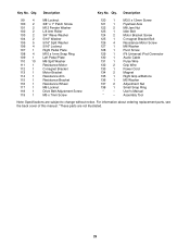
Description Key No. For information about ordering replacement parts, see the back cover of this manual. *These parts are subject to change without notice. Description 99 4 100 2 101 2 102 2 103 2 104 2 105 5 106 4 107 1 108 4 109 1 110 10 111 1 112 1 113 1 114 1 115 1 ...
Description Key No. For information about ordering replacement parts, see the back cover of this manual. *These parts are subject to change without notice. Description 99 4 100 2 101 2 102 2 103 2 104 2 105 5 106 4 107 1 108 4 109 1 110 10 111 1 112 1 113 1 114 1 115 1 ...
English Manual
Page 32
...that vary from the date of the product; To help us assist you, be responsible for commercial or rental purposes. Parts and labor are not followed, if the product is abused or improperly or abnormally used for a minimal handling charge. If replacement...313993 R0112A Printed in connection with respect to the original purchaser (customer). This warranty provides specific legal rights; ORDERING REPLACEMENT PARTS To order replacement parts, please see the PART LIST and the EXPLODED DRAWING near the end of this manual. Accordingly, the above is not responsible or liable for ...
...that vary from the date of the product; To help us assist you, be responsible for commercial or rental purposes. Parts and labor are not followed, if the product is abused or improperly or abnormally used for a minimal handling charge. If replacement...313993 R0112A Printed in connection with respect to the original purchaser (customer). This warranty provides specific legal rights; ORDERING REPLACEMENT PARTS To order replacement parts, please see the PART LIST and the EXPLODED DRAWING near the end of this manual. Accordingly, the above is not responsible or liable for ...


