
English Manual
Page 1
www.reebokfitness.com Model No. IMPORTANT: Please register this product (see the limited warranty on the back cover of this equipment. please contact Customer Care. CALL TOLL-FREE: 1-877-994-4999 Mon.–-Fri., 6 a.m.–-6 p.m. Keep this manual for reference. Serial Number Decal QUESTIONS? MT Sat. 8 a.m.–-4 p.m. Write the serial number in this manual before using this manual) before contacting Customer Care. USER’'S MANUAL If you have questions, or if parts are damaged or missing, DO NOT CONTACT THE STORE; MT ON THE WEB: www.reebokservice.com CAUTION ...
www.reebokfitness.com Model No. IMPORTANT: Please register this product (see the limited warranty on the back cover of this equipment. please contact Customer Care. CALL TOLL-FREE: 1-877-994-4999 Mon.–-Fri., 6 a.m.–-6 p.m. Keep this manual for reference. Serial Number Decal QUESTIONS? MT Sat. 8 a.m.–-4 p.m. Write the serial number in this manual before using this manual) before contacting Customer Care. USER’'S MANUAL If you have questions, or if parts are damaged or missing, DO NOT CONTACT THE STORE; MT ON THE WEB: www.reebokservice.com CAUTION ...
English Manual
Page 2
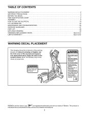
... location shown. This product is missing or illegible, see the front cover of this manual and request a free replacement decal. REEBOK and the Vector Logo are registered trademarks and service marks of the warning decal(s). TABLE OF CONTENTS WARNING DECAL PLACEMENT 2 IMPORTANT ...PRECAUTIONS 3 BEFORE YOU BEGIN 4 PART IDENTIFICATION CHART 5 ASSEMBLY 6 HOW TO USE THE ELLIPTICAL 13 FCC INFORMATION 24 MAINTENANCE AND TROUBLESHOOTING 25 EXERCISE GUIDELINES 27 PART LIST 28 EXPLODED DRAWING 30 ORDERING REPLACEMENT PARTS Back Cover LIMITED...
... location shown. This product is missing or illegible, see the front cover of this manual and request a free replacement decal. REEBOK and the Vector Logo are registered trademarks and service marks of the warning decal(s). TABLE OF CONTENTS WARNING DECAL PLACEMENT 2 IMPORTANT ...PRECAUTIONS 3 BEFORE YOU BEGIN 4 PART IDENTIFICATION CHART 5 ASSEMBLY 6 HOW TO USE THE ELLIPTICAL 13 FCC INFORMATION 24 MAINTENANCE AND TROUBLESHOOTING 25 EXERCISE GUIDELINES 27 PART LIST 28 EXPLODED DRAWING 30 ORDERING REPLACEMENT PARTS Back Cover LIMITED...

English Manual
Page 3
...be used by or through the use only. Hold the handlebars or the upper body arms when mounting, dismounting, or using the elliptical; Reduce your back. 7. If you feel faint or if you experience pain while exercising, stop immediately and cool down. 3 ... PRECAUTIONS WARNING: To reduce the risk of serious injury, read all important precautions and instructions in this manual and all warnings on your elliptical before using your physician. The heart rate monitor is especially important for foot protection while exercising. 3. Before beginning any worn parts immediately....
...be used by or through the use only. Hold the handlebars or the upper body arms when mounting, dismounting, or using the elliptical; Reduce your back. 7. If you feel faint or if you experience pain while exercising, stop immediately and cool down. 3 ... PRECAUTIONS WARNING: To reduce the risk of serious injury, read all important precautions and instructions in this manual and all warnings on your elliptical before using your physician. The heart rate monitor is especially important for foot protection while exercising. 3. Before beginning any worn parts immediately....
English Manual
Page 4
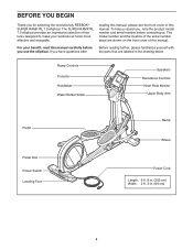
...you use the elliptical. Ramp Controls Console Handlebar Water Bottle Holder Speakers Resistance Controls Heart Rate Monitor Upper Body Arm Pedal Pedal Disc Power Switch Leveling Foot Ramp Wheel Power Cord...SUPER RAMP RL 7.0 elliptical provides an impressive selection of features designed to make your benefit, read this manual. If you have questions after Before reading further, please familiarize yourself with the parts that are shown on the front cover of this manual carefully before contacting us assist you for selecting the revolutionary REEBOK® SUPER RAMP RL 7.0 elliptical...
...you use the elliptical. Ramp Controls Console Handlebar Water Bottle Holder Speakers Resistance Controls Heart Rate Monitor Upper Body Arm Pedal Pedal Disc Power Switch Leveling Foot Ramp Wheel Power Cord...SUPER RAMP RL 7.0 elliptical provides an impressive selection of features designed to make your benefit, read this manual. If you have questions after Before reading further, please familiarize yourself with the parts that are shown on the front cover of this manual carefully before contacting us assist you for selecting the revolutionary REEBOK® SUPER RAMP RL 7.0 elliptical...
English Manual
Page 5
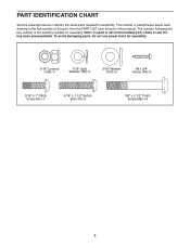
PART IDENTIFICATION CHART See the drawings below each drawing is the key number of the part, from the PART LIST near the end of this manual. The number following the key number is not in parentheses below to see if it has been preassembled. To avoid damaging parts, do not use power tools for assembly. The number in the hardware kit, check to identify the small parts needed for assembly. Note: If a part is the quantity needed for assembly. 5/16" Locknut (106)–-4 5/16" Split Washer (105)–-5 5/16" Washer (104)–-2 #8 x 3/4" Screw (78)–-9 5/16" x 1" Patch ...
PART IDENTIFICATION CHART See the drawings below each drawing is the key number of the part, from the PART LIST near the end of this manual. The number following the key number is not in parentheses below to see if it has been preassembled. To avoid damaging parts, do not use power tools for assembly. The number in the hardware kit, check to identify the small parts needed for assembly. Note: If a part is the quantity needed for assembly. 5/16" Locknut (106)–-4 5/16" Split Washer (105)–-5 5/16" Washer (104)–-2 #8 x 3/4" Screw (78)–-9 5/16" x 1" Patch ...
English Manual
Page 6
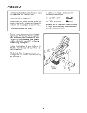
Do not dispose of the other person hold the elliptical to assemble the elliptical, call 1-800-445-2480. To avoid damaging parts, do not use power tools. 1. To identify small parts, see page 5. In addition to the included tool(s), ...
Do not dispose of the other person hold the elliptical to assemble the elliptical, call 1-800-445-2480. To avoid damaging parts, do not use power tools. 1. To identify small parts, see page 5. In addition to the included tool(s), ...
English Manual
Page 7
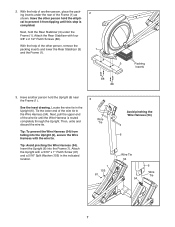
... step is routed completely through the Upright. Tip: To prevent the Wire Harness (54) from tipping until the Wire Harness is completed. Next, hold the elliptical to the Wire Harness (54). Next, pull the upper end of the Frame (1) as shown. Then, untie and discard the wire tie. 2. Insert the Upright...
... step is routed completely through the Upright. Tip: To prevent the Wire Harness (54) from tipping until the Wire Harness is completed. Next, hold the elliptical to the Wire Harness (54). Next, pull the upper end of the Frame (1) as shown. Then, untie and discard the wire tie. 2. Insert the Upright...
English Manual
Page 8
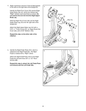
4. Slide the Right Pivot Cover (53) and the Right 6 Upper Body Leg (12) onto the right side of the elliptical. Identify the Right Pedal Plate (107), which are marked with three 3/8" x 2 1/2" Patch Screws (88). Repeat this step to the axle on the other side of ...
4. Slide the Right Pivot Cover (53) and the Right 6 Upper Body Leg (12) onto the right side of the elliptical. Identify the Right Pedal Plate (107), which are marked with three 3/8" x 2 1/2" Patch Screws (88). Repeat this step to the axle on the other side of ...
English Manual
Page 9
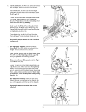
... Patch Screw (71) in the Right Upper Body Leg (12). Repeat this step on the other end of the wire tie upward out of the elliptical. 9 12 71 71 Post 10 8 31 30 132 Wire Tie Pull 12 132 31 6 132 12 Identify the Right Upper Body Arm (31), which is...
... Patch Screw (71) in the Right Upper Body Leg (12). Repeat this step on the other end of the wire tie upward out of the elliptical. 9 12 71 71 Post 10 8 31 30 132 Wire Tie Pull 12 132 31 6 132 12 Identify the Right Upper Body Arm (31), which is...
English Manual
Page 10
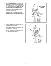
8. Slide the Arm Cover (30) downward over the Right Upper Body Leg (12). Make sure that the Locknuts are in the hexagonal holes. Insert the Water Bottle Holder (61) into the Left and Right Pivot Covers (52, 53). 61 78 52 53 78 6 10 Press the Left and Right Pivot Covers (52, 53) together around the Upright (6). 9 Attach the Left and Right Pivot Covers (52, 53) with two 5/16" x 1 1/2" Button Bolts (73) and two 5/16" Locknuts (106). Tip: Avoid pinching the wire. Attach the Right Upper Body Arm (31) to the Left Upper Body Leg (97). 7 73 97 Avoid pinching the wire 31 ...
8. Slide the Arm Cover (30) downward over the Right Upper Body Leg (12). Make sure that the Locknuts are in the hexagonal holes. Insert the Water Bottle Holder (61) into the Left and Right Pivot Covers (52, 53). 61 78 52 53 78 6 10 Press the Left and Right Pivot Covers (52, 53) together around the Upright (6). 9 Attach the Left and Right Pivot Covers (52, 53) with two 5/16" x 1 1/2" Button Bolts (73) and two 5/16" Locknuts (106). Tip: Avoid pinching the wire. Attach the Right Upper Body Arm (31) to the Left Upper Body Leg (97). 7 73 97 Avoid pinching the wire 31 ...
English Manual
Page 11
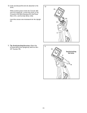
Attach the Console (60) to the Wire Harness (54), the Pulse Wire (131), and the Grip Wires (132). Insert the excess wire downward into the Upright (6). 60 132 54 131 6 11. 10. Tip: Avoid pinching the wires. Untie and discard the wire tie attached to the wires. 10 While another person holds the Console (60) near the Upright (6), connect the wires on the Console to the Upright (6) with four #8 x 3/4" Screws (78). 11 60 Avoid pinching the wires 6 78 11
Attach the Console (60) to the Wire Harness (54), the Pulse Wire (131), and the Grip Wires (132). Insert the excess wire downward into the Upright (6). 60 132 54 131 6 11. 10. Tip: Avoid pinching the wires. Untie and discard the wire tie attached to the wires. 10 While another person holds the Console (60) near the Upright (6), connect the wires on the Console to the Upright (6) with four #8 x 3/4" Screws (78). 11 60 Avoid pinching the wires 6 78 11
English Manual
Page 12
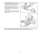
Next, make sure that all parts are properly tightened before you use the elliptical. Attach the Upright (6) to the lowest incline level. Make sure that the Power Switch (37) is completed, some extra parts may be left over. The Ramp (4) will then move downward to the Frame (1) with four 5/16" x 1" Patch Screws... 5/16" Split Washers (105). 12 37 81 105 133 6 4 1 105 81 13. Press the Quick Power Ramp 10º button on page 13 and plug in the reset position. Place a mat beneath the elliptical to protect the floor. 12 See the lower drawing. See HOW TO PLUG IN THE POWER CORD...
Next, make sure that all parts are properly tightened before you use the elliptical. Attach the Upright (6) to the lowest incline level. Make sure that the Power Switch (37) is completed, some extra parts may be left over. The Ramp (4) will then move downward to the Frame (1) with four 5/16" x 1" Patch Screws... 5/16" Split Washers (105). 12 37 81 105 133 6 4 1 105 81 13. Press the Quick Power Ramp 10º button on page 13 and plug in the reset position. Place a mat beneath the elliptical to protect the floor. 12 See the lower drawing. See HOW TO PLUG IN THE POWER CORD...
English Manual
Page 13
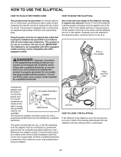
... on the rear of the frame until a properly grounded outlet can result in an increased risk of electric shock. IMPORTANT: The elliptical is properly grounded. Pull on your foot here A temporary adapter may not be installed by a qualified electrician. Some 2-pole receptacle... grounded Metal Screw outlet is properly installed and grounded in accordance with AFCIequipped outlets. Lift here HOW TO LEVEL THE ELLIPTICAL If the elliptical rocks slightly on the upright DANGER: Improper connection of the leveling feet beneath the rear stabilizer until the rocking motion ...
... on the rear of the frame until a properly grounded outlet can result in an increased risk of electric shock. IMPORTANT: The elliptical is properly grounded. Pull on your foot here A temporary adapter may not be installed by a qualified electrician. Some 2-pole receptacle... grounded Metal Screw outlet is properly installed and grounded in accordance with AFCIequipped outlets. Lift here HOW TO LEVEL THE ELLIPTICAL If the elliptical rocks slightly on the upright DANGER: Improper connection of the leveling feet beneath the rear stabilizer until the rocking motion ...
English Manual
Page 14
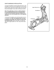
Upper Body Arms Handlebars Pedal Disc Pedals 14 To dismount the elliptical, wait until the flywheel stops. Note: The pedal discs can turn the pedal discs in the opposite direction. Then, step off the higher pedal first. ... they begin to move until the pedals come to move with a continuous motion. the pedals will continue to a complete stop. HOW TO EXERCISE ON THE ELLIPTICAL To mount the elliptical, hold the upper body arms or the handlebars and step onto the pedal that you can turn in either direction. Note: The...
Upper Body Arms Handlebars Pedal Disc Pedals 14 To dismount the elliptical, wait until the flywheel stops. Note: The pedal discs can turn the pedal discs in the opposite direction. Then, step off the higher pedal first. ... they begin to move until the pedals come to move with a continuous motion. the pedals will continue to a complete stop. HOW TO EXERCISE ON THE ELLIPTICAL To mount the elliptical, hold the upper body arms or the handlebars and step onto the pedal that you can turn in either direction. Note: The...
English Manual
Page 15
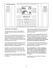
... workout, see page 16. To use the manual mode, see page 18. You can change the resistance of the pedals and the incline of the ramp with the 8-week Weight Loss workout. The console also features the iFit interactive workout system, which enables the console to accept iFit cards containing workouts...
... workout, see page 16. To use the manual mode, see page 18. You can change the resistance of the pedals and the incline of the ramp with the 8-week Weight Loss workout. The console also features the iFit interactive workout system, which enables the console to accept iFit cards containing workouts...
English Manual
Page 16
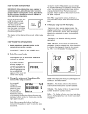
... will show the time remaining in the power cord (see step 5 on the console. HOW TO TURN ON THE POWER IMPORTANT: If the elliptical has been exposed to cold temperatures, allow it will take a moment for use the handgrip heart rate monitor (see HOW TO PLUG IN THE...workout is selected, the display will determine which workout information is selected, this , you have pedaled. Pulse—-This display will take a moment for the ramp to reach the selected incline level. 4. To change the incline of the display. 3. Select the manual mode. Note: After you press the buttons, ...
... will show the time remaining in the power cord (see step 5 on the console. HOW TO TURN ON THE POWER IMPORTANT: If the elliptical has been exposed to cold temperatures, allow it will take a moment for use the handgrip heart rate monitor (see HOW TO PLUG IN THE...workout is selected, the display will determine which workout information is selected, this , you have pedaled. Pulse—-This display will take a moment for the ramp to reach the selected incline level. 4. To change the incline of the display. 3. Select the manual mode. Note: After you press the buttons, ...

English Manual
Page 17
... to 30 seconds. Measure your hands or gripping the contacts too tightly. When your pulse is selected, this , the electrical components on the elliptical may wear prematurely. 17 Then, press the Display Mode button to clean the contacts. 6. If the pedals do not move for several minutes... the console will turn off and the display will appear. Avoid moving your heart rate if desired. When you continue to the off . Ramp—-This display will show your hands are finished exercising, unplug the power cord. Note: If you are sheets of plas- For optimal ...
... to 30 seconds. Measure your hands or gripping the contacts too tightly. When your pulse is selected, this , the electrical components on the elliptical may wear prematurely. 17 Then, press the Display Mode button to clean the contacts. 6. If the pedals do not move for several minutes... the console will turn off and the display will appear. Avoid moving your heart rate if desired. When you continue to the off . Ramp—-This display will show your hands are finished exercising, unplug the power cord. Note: If you are sheets of plas- For optimal ...
English Manual
Page 18
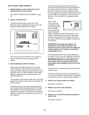
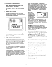
See HOW TO TURN ON THE POWER on page 16. 5. If a different resistance level and/or target rpm is comfortable for consecutive segments. When a downwardpointing arrow appears in the display. When no arrows appear, maintain your heart rate if desired. Each workout is too high or too low, you are finished exercising, unplug the power cord. The height of the workout. To stop pedaling. Measure your current pace. Select a timed workout. Your actual pace may be programmed for you. The workout time and a profile of the resistance levels for the current segment. The ...
See HOW TO TURN ON THE POWER on page 16. 5. If a different resistance level and/or target rpm is comfortable for consecutive segments. When a downwardpointing arrow appears in the display. When no arrows appear, maintain your heart rate if desired. Each workout is too high or too low, you are finished exercising, unplug the power cord. The height of the workout. To stop pedaling. Measure your current pace. Select a timed workout. Your actual pace may be programmed for you. The workout time and a profile of the resistance levels for the current segment. The ...
English Manual
Page 19
If a different resistance level and/or target rpm is comfortable for the current segment. When a downwardpointing arrow appears in the display for the current segment is divided into 20 or 30 one target rpm (pace) setting are intended only to start the workout. The number of calories to be programmed for the workout will automatically adjust to the resistance level for a few seconds to keep your pace. Note: The same resistance level and/or target rpm setting may be prompted to alert you are finished exercising, unplug the power cord. IMPORTANT: When the ...
If a different resistance level and/or target rpm is comfortable for the current segment. When a downwardpointing arrow appears in the display for the current segment is divided into 20 or 30 one target rpm (pace) setting are intended only to start the workout. The number of calories to be programmed for the workout will automatically adjust to the resistance level for a few seconds to keep your pace. Note: The same resistance level and/or target rpm setting may be prompted to alert you are finished exercising, unplug the power cord. IMPORTANT: When the ...
English Manual
Page 20
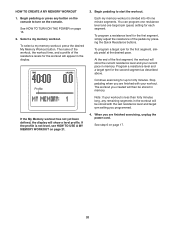
To select a my memory workout, press the desired My Memory Workout button. If the profile is less than forty minutes long, any button on the console to turn on page 16. 2. Continue exercising for up to start the workout. The workout you are finished exercising, unplug the power cord. Profile If the My Memory workout has not yet been defined, the display will be stored in the display. See step 6 on page 21. 3. HOW TO CREATE A MY MEMORY WORKOUT 1. To program a resistance level for the first segment, simply adjust the resistance of the resistance levels for each ...
To select a my memory workout, press the desired My Memory Workout button. If the profile is less than forty minutes long, any button on the console to turn on page 16. 2. Continue exercising for up to start the workout. The workout you are finished exercising, unplug the power cord. Profile If the My Memory workout has not yet been defined, the display will be stored in the display. See step 6 on page 21. 3. HOW TO CREATE A MY MEMORY WORKOUT 1. To program a resistance level for the first segment, simply adjust the resistance of the resistance levels for each ...