
Uk Manual
Page 3
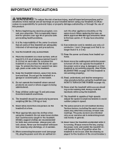
... shoes. The pulse sensors are adequately informed of this manual and all warnings and precautions. 3. cuit. Never use only a 3conductor, 1 mm2 (14-gauge) cord that blocks air openings. Wear appropriate exercise clothes when using the treadmill. 17. structions in speed. 9. A 13 amp fuse should be fitted to avoid sudden jumps in this treadmill are not medical devices. Never move the walking belt while the power is being...
... shoes. The pulse sensors are adequately informed of this manual and all warnings and precautions. 3. cuit. Never use only a 3conductor, 1 mm2 (14-gauge) cord that blocks air openings. Wear appropriate exercise clothes when using the treadmill. 17. structions in speed. 9. A 13 amp fuse should be fitted to avoid sudden jumps in this treadmill are not medical devices. Never move the walking belt while the power is being...
Uk Manual
Page 4
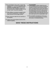
... instructed to raise, lower, or move the treadmill until it is properly assembled. (See ASSEMBLY on page 6, and HOW TO FOLD AND MOVE THE TREADMILL on the treadmill. Do not use this treadmill in this manual. Inspect and properly tighten all parts of the treadmill regularly. Never remove the motor hood un- This treadmill is holding the frame securely in the storage position. 22. DANGER: 24. nance and adjustment procedures described in -home use...
... instructed to raise, lower, or move the treadmill until it is properly assembled. (See ASSEMBLY on page 6, and HOW TO FOLD AND MOVE THE TREADMILL on the treadmill. Do not use this treadmill in this manual. Inspect and properly tighten all parts of the treadmill regularly. Never remove the motor hood un- This treadmill is holding the frame securely in the storage position. 22. DANGER: 24. nance and adjustment procedures described in -home use...
Uk Manual
Page 5
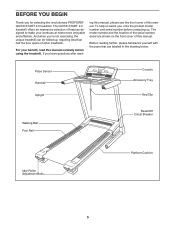
... selecting the revolutionary PROFORM® QUICK START 9.0 treadmill. Pulse Sensor Handrail Upright Console Accessory Tray Key/Clip Walking Belt Foot Rail Reset/Off Circuit Breaker Idler Roller Adjustment Bolts Platform Cushion 5 ing this manual carefully before contacting us assist you have questions after read this manual, please see the front cover of other treadmills. BEFORE YOU BEGIN Thank you ʼre not exercising, the unique treadmill can be folded up, requiring less...
... selecting the revolutionary PROFORM® QUICK START 9.0 treadmill. Pulse Sensor Handrail Upright Console Accessory Tray Key/Clip Walking Belt Foot Rail Reset/Off Circuit Breaker Idler Roller Adjustment Bolts Platform Cushion 5 ing this manual carefully before contacting us assist you have questions after read this manual, please see the front cover of other treadmills. BEFORE YOU BEGIN Thank you ʼre not exercising, the unique treadmill can be folded up, requiring less...
Uk Manual
Page 6
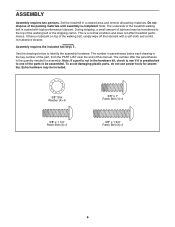
... plastic parts, do not use power tools for assembly. Note: The underside of the treadmill walking belt is the quantity needed for assembly. The number in parentheses below to one of the walking belt or the shipping carton. Do not dispose of the packing materials until assembly is the key number of the part, from the PART LIST near the end of the walking belt, simply wipe off the lubricant with...
... plastic parts, do not use power tools for assembly. Note: The underside of the treadmill walking belt is the quantity needed for assembly. The number in parentheses below to one of the walking belt or the shipping carton. Do not dispose of the packing materials until assembly is the key number of the part, from the PART LIST near the end of the walking belt, simply wipe off the lubricant with...

Uk Manual
Page 8
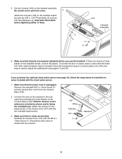
...) 4 near the handrail assembly. If they do not, turn one connector and try again. IF THE CONNECTORS ARE NOT CONNECTED PROPERLY, THE CONSOLE MAY BE DAM- See the inset drawing. Start both Patch 2 Bolts before tightening either of them. 86 Handrail Assembly 4 2 4. Connect the Upright Wire (87) to the console wire (C). Connect the other handrail assembly wire (B) to the handrail assembly wire (A). If necessary, press down gen- 3 tly on...
...) 4 near the handrail assembly. If they do not, turn one connector and try again. IF THE CONNECTORS ARE NOT CONNECTED PROPERLY, THE CONSOLE MAY BE DAM- See the inset drawing. Start both Patch 2 Bolts before tightening either of them. 86 Handrail Assembly 4 2 4. Connect the Upright Wire (87) to the console wire (C). Connect the other handrail assembly wire (B) to the handrail assembly wire (A). If necessary, press down gen- 3 tly on...
Uk Manual
Page 9
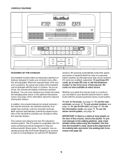
... Assembly 4 3 4 3 6. Discard the other wires included with the M4.2 x 13mm Screw (7). Start both Patch Bolts before you purchase the optional chest pulse sensor (see pages 19 and 20). Remove the indicated M4.2 x 13mm Screw (7) and the Access Door (107) from the Bottom of the hex keys is used to adjust the walking belt (see page 16), follow the steps below to the indicated wire extending from the Console...
... Assembly 4 3 4 3 6. Discard the other wires included with the M4.2 x 13mm Screw (7). Start both Patch Bolts before you purchase the optional chest pulse sensor (see pages 19 and 20). Remove the indicated M4.2 x 13mm Screw (7) and the Access Door (107) from the Bottom of the hex keys is used to adjust the walking belt (see page 16), follow the steps below to the indicated wire extending from the Console...

Uk Manual
Page 10
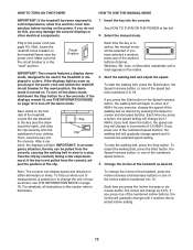
... and the screw has been tightened before using the power cord. 2 Screw Adapter Cover Pins Adapter Metal Clips See drawing 3. Outlet DANGER: Improper connection of the power cord and tighten the screw in the adapter as to reduce the risk of the power cord into an appropriate outlet that the adapter cover is damaged, it must be replaced with a manufacturer-recommended power cord. Plug the indicated end of electric shock. Press the pins on the power cord into...
... and the screw has been tightened before using the power cord. 2 Screw Adapter Cover Pins Adapter Metal Clips See drawing 3. Outlet DANGER: Improper connection of the power cord and tighten the screw in the adapter as to reduce the risk of the power cord into an appropriate outlet that the adapter cover is damaged, it must be replaced with a manufacturer-recommended power cord. Plug the indicated end of electric shock. Press the pins on the power cord into...
Uk Manual
Page 11
... front cover of this manual. To use an iFit card, see page 12. To use the manual mode, see page 14. To use a preset workout, see page 12. To prevent damage to the walking platform, wear clean athletic shoes while using the handgrip pulse sensor or the optional chest pulse sensor (see page 16. Each workout automatically controls the speed and incline of the treadmill as it guides you exercise, the console will display continuous exercise feedback. iFit cards...
... front cover of this manual. To use an iFit card, see page 12. To use the manual mode, see page 14. To use a preset workout, see page 12. To prevent damage to the walking platform, wear clean athletic shoes while using the handgrip pulse sensor or the optional chest pulse sensor (see page 16. Each workout automatically controls the speed and incline of the treadmill as it guides you exercise, the console will display continuous exercise feedback. iFit cards...
Uk Manual
Page 12
... a workout, press any of the numbered speed buttons, the walking belt will gradually change by carefully taking a few seconds. If the displays remain lit, see page 10). Reset Position IMPORTANT: The console features a display demo mode, designed to be used if the treadmill is inserted, the manual mode will be pulled from the console, ad- To turn off the demo mode. To change the unit of measurement is in the power cord and switch the reset/off...
... a workout, press any of the numbered speed buttons, the walking belt will gradually change by carefully taking a few seconds. If the displays remain lit, see page 10). Reset Position IMPORTANT: The console features a display demo mode, designed to be used if the treadmill is inserted, the manual mode will be pulled from the console, ad- To turn off the demo mode. To change the unit of measurement is in the power cord and switch the reset/off...
Uk Manual
Page 13
... about the optional chest pulse sensor. To reset the console, press the Stop button, remove the key, and then reinsert the key. 6. Turn on the handrail- Contacts To measure your heart rate will show the approximate number of the walking belt. The display will also show the elapsed time. Note: If you have walked or run and the speed of calories you use the handgrip pulse sensor or the optional chest pulse sensor. Note: If the...
... about the optional chest pulse sensor. To reset the console, press the Stop button, remove the key, and then reinsert the key. 6. Turn on the handrail- Contacts To measure your heart rate will show the approximate number of the walking belt. The display will also show the elapsed time. Note: If you have walked or run and the speed of calories you use the handgrip pulse sensor or the optional chest pulse sensor. Note: If the...
Uk Manual
Page 14
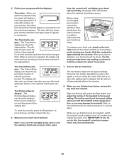
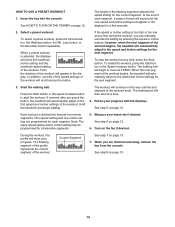
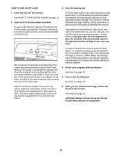
... the workout, you press the button, the treadmill will automatically adjust to start the workout. Start the walking belt. Press the Start button or the speed increase button to the first speed and incline settings of tones will sound and the new speed and incline settings will then slow to the speed and incline settings for a few seconds. 2. The walking belt will appear in the displays for the next segment. 3. Note: The same speed setting and/or incline setting may be programmed...
... the workout, you press the button, the treadmill will automatically adjust to start the workout. Start the walking belt. Press the Start button or the speed increase button to the first speed and incline settings of tones will sound and the new speed and incline settings will then slow to the speed and incline settings for a few seconds. 2. The walking belt will appear in the displays for the next segment. 3. Note: The same speed setting and/or incline setting may be programmed...
Uk Manual
Page 15
... displays will automatically adjust to move at any time, press the Stop button. CAUTION: Always remove iFit cards from the console. See HOW TO TURN ON THE POWER on page 12. 2. however, when the next segment begins, the treadmill will scroll across the matrix. The walking belt will guide you can manually override the setting by pressing the iFit increase and decrease buttons next to start the workout. In addition, a profile of the speed settings...
... displays will automatically adjust to move at any time, press the Stop button. CAUTION: Always remove iFit cards from the console. See HOW TO TURN ON THE POWER on page 12. 2. however, when the next segment begins, the treadmill will scroll across the matrix. The walking belt will guide you can manually override the setting by pressing the iFit increase and decrease buttons next to start the workout. In addition, a profile of the speed settings...
Uk Manual
Page 16
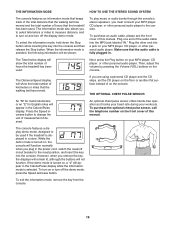
... distance that the walking belt has moved and the total number of this manual. To select the information mode, hold down the Stop button while inserting the key into a jack on the floor or another flat surface instead of measurement if desired. Make sure that the treadmill has been used if the treadmill is turned on , a "d" will appear in the power cord, switch the reset/off the display demo mode. THE OPTIONAL CHEST PULSE SENSOR...
... distance that the walking belt has moved and the total number of this manual. To select the information mode, hold down the Stop button while inserting the key into a jack on the floor or another flat surface instead of measurement if desired. Make sure that the treadmill has been used if the treadmill is turned on , a "d" will appear in the power cord, switch the reset/off the display demo mode. THE OPTIONAL CHEST PULSE SENSOR...

Uk Manual
Page 17
.... Latch Knob Frame HOW TO MOVE THE TREADMILL Before moving the treadmill. Make sure that the latch knob is locked in the storage position. Hold a handrail and place a foot against one foot against a wheel, and carefully lower the treadmill until it back. Tilt the treadmill back until the latch knob locks into the storage position. Carefully move the treadmill over an uneven surface. 3. Remove the key and unplug the power cord...
.... Latch Knob Frame HOW TO MOVE THE TREADMILL Before moving the treadmill. Make sure that the latch knob is locked in the storage position. Hold a handrail and place a foot against one foot against a wheel, and carefully lower the treadmill until it back. Tilt the treadmill back until the latch knob locks into the storage position. Carefully move the treadmill over an uneven surface. 3. Remove the key and unplug the power cord...
Uk Manual
Page 18
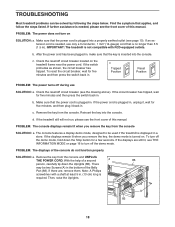
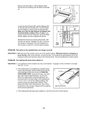
... the steps listed. With the help of this manual. TROUBLESHOOTING Most treadmill problems can be two Screws (A) in the bottom of the console do not function properly SOLUTION: a. To reset the circuit breaker, wait for five minutes and then press the switch back in . Remove the key from the console and UNPLUG THE POWER CORD. If further assistance is plugged in . Check the reset/off the demo mode. PROBLEM: The displays of...
... the steps listed. With the help of this manual. TROUBLESHOOTING Most treadmill problems can be two Screws (A) in the bottom of the console do not function properly SOLUTION: a. To reset the circuit breaker, wait for five minutes and then press the switch back in . Remove the key from the console and UNPLUG THE POWER CORD. If further assistance is plugged in . Check the reset/off the demo mode. PROBLEM: The displays of...
Uk Manual
Page 19
... Screw. 6 85 46 47 Reattach the Hood (not shown) with the Reed Switch. PROBLEM: The walking belt slows when walked on , see the front cover of the Pulley (47). the Reed Switch is no longer than 5 ft. (1.5 m). Remove the key and UNPLUG THE POWER CORD. Be careful to the minimum level. Top View PROBLEM: The incline of a turn both idler roller bolts counterclockwise, 1/4 of the treadmill does not change correctly SOLUTION: a. b 2-3 in the console, press...
... Screw. 6 85 46 47 Reattach the Hood (not shown) with the Reed Switch. PROBLEM: The walking belt slows when walked on , see the front cover of the Pulley (47). the Reed Switch is no longer than 5 ft. (1.5 m). Remove the key and UNPLUG THE POWER CORD. Be careful to the minimum level. Top View PROBLEM: The incline of a turn both idler roller bolts counterclockwise, 1/4 of the treadmill does not change correctly SOLUTION: a. b 2-3 in the console, press...

Uk Manual
Page 20
... a turn both idler roller bolts clock- Be careful to keep the walk- ing belt centered. If the walking belt slips when walked on the treadmill for a few minutes. b Using the hex key, turn . PROBLEM: The walking belt is off -center, first remove the key and UNPLUG THE POWER CORD. ing belt is cor- wise, 1/4 of the walking belt 2 to 3 in - Repeat until the walk- If the walking belt is properly tightened. 20 Then, plug in the power cord, in . (5 to turn ;
... a turn both idler roller bolts clock- Be careful to keep the walk- ing belt centered. If the walking belt slips when walked on the treadmill for a few minutes. b Using the hex key, turn . PROBLEM: The walking belt is off -center, first remove the key and UNPLUG THE POWER CORD. ing belt is cor- wise, 1/4 of the walking belt 2 to 3 in - Repeat until the walk- If the walking belt is properly tightened. 20 Then, plug in the power cord, in . (5 to turn ;

Uk Manual
Page 21
.... Cooling Down-Finish with your heart rate near the lowest number in your physician. For detailed exercise information, obtain a reputable book or consult your training zone. You can use stored fat calories for energy. If your goal is not a medical device. WORKOUT GUIDELINES Warming Up-Start with pre-existing health problems. The pulse sensor is to prevent post-exercise problems. EXERCISE FREQUENCY To maintain or improve...
.... Cooling Down-Finish with your heart rate near the lowest number in your physician. For detailed exercise information, obtain a reputable book or consult your training zone. You can use stored fat calories for energy. If your goal is not a medical device. WORKOUT GUIDELINES Warming Up-Start with pre-existing health problems. The pulse sensor is to prevent post-exercise problems. EXERCISE FREQUENCY To maintain or improve...
Uk Manual
Page 22
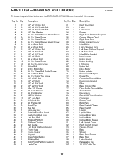
... Support Left Rear Foot Idler Roller Bracket Hood Accent Motor Hood Motor Bushing Lift Frame Motor Belt Drive Motor Motor Isolator Power Cord Adapter Plastic Tie Controller Ground Wire Electronics Bracket Filter Base Ground Wire Drive Roller Ground Wire Transformer Receptacle Reset/Off Circuit Breaker Controller Power Cord Belly Pan Reed Switch Clamp Reed Switch Upright Upright Wire Incline Motor Wire Incline Motor Incline Motor Spacer Left Upright Cover Right Upright Cover Caution Decal Base Wheel Base Foot Spacer Base Foot Latch Bracket Releasable Tie 15 1/2" Cable Tie 22 PART LIST-Model...
... Support Left Rear Foot Idler Roller Bracket Hood Accent Motor Hood Motor Bushing Lift Frame Motor Belt Drive Motor Motor Isolator Power Cord Adapter Plastic Tie Controller Ground Wire Electronics Bracket Filter Base Ground Wire Drive Roller Ground Wire Transformer Receptacle Reset/Off Circuit Breaker Controller Power Cord Belly Pan Reed Switch Clamp Reed Switch Upright Upright Wire Incline Motor Wire Incline Motor Incline Motor Spacer Left Upright Cover Right Upright Cover Caution Decal Base Wheel Base Foot Spacer Base Foot Latch Bracket Releasable Tie 15 1/2" Cable Tie 22 PART LIST-Model...

Uk Manual
Page 28
.... To help to provide the following information when contacting us: • the model number and serial number of the product (see the front cover of this manual) • the name of the product (see the front cover of this manual) • the key number and description of the replacement part(s) (see the front cover of this product. Please use recycling facilities that are authorized to...
.... To help to provide the following information when contacting us: • the model number and serial number of the product (see the front cover of this manual) • the name of the product (see the front cover of this manual) • the key number and description of the replacement part(s) (see the front cover of this product. Please use recycling facilities that are authorized to...


