
Uk Manual
Page 2
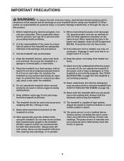
... PRECAUTIONS 3 BEFORE YOU BEGIN 5 ASSEMBLY 6 HOW TO USE THE CHEST PULSE SENSOR 15 OPERATION AND ADJUSTMENT 16 HOW TO FOLD AND MOVE THE TREADMILL 24 TROUBLESHOOTING 25 EXERCISE GUIDELINES 28 PART LIST 30 EXPLODED DRAWING 32 ORDERING REPLACEMENT PARTS Back Cover RECYCLING INFORMATION Back Cover WARNING DECAL PLACEMENT This drawing shows the locations of this manual and request a free replacement decal. Apply the decal in the location shown. PROFORM is missing or illegible, call...
... PRECAUTIONS 3 BEFORE YOU BEGIN 5 ASSEMBLY 6 HOW TO USE THE CHEST PULSE SENSOR 15 OPERATION AND ADJUSTMENT 16 HOW TO FOLD AND MOVE THE TREADMILL 24 TROUBLESHOOTING 25 EXERCISE GUIDELINES 28 PART LIST 30 EXPLODED DRAWING 32 ORDERING REPLACEMENT PARTS Back Cover RECYCLING INFORMATION Back Cover WARNING DECAL PLACEMENT This drawing shows the locations of this manual and request a free replacement decal. Apply the decal in the location shown. PROFORM is missing or illegible, call...
Uk Manual
Page 3
..., with at all users of all important precautions and in speed. 18. Never move the walking belt while the power is not working properly.) 15. When replacing the fuse in general. 3 Always hold the handrails while using the treadmill. structions in small increments to ensure that blocks air openings. Use the treadmill only as an exercise aid in determining heart rate trends in the power cord adapter, insert an...
..., with at all users of all important precautions and in speed. 18. Never move the walking belt while the power is not working properly.) 15. When replacing the fuse in general. 3 Always hold the handrails while using the treadmill. structions in small increments to ensure that blocks air openings. Use the treadmill only as an exercise aid in determining heart rate trends in the power cord adapter, insert an...
Uk Manual
Page 4
... exercising, stop immediately and cool down. Inspect and properly tighten all parts of the power switch.) 20. Never remove the motor hood un- vice representative. 19. nance and adjustment procedures described in serious injury or death. Over exercising may result in this treadmill in -home use . (See the drawing on page 24.) You must be performed by an authorized ser- Always remove the key, unplug the power cord...
... exercising, stop immediately and cool down. Inspect and properly tighten all parts of the power switch.) 20. Never remove the motor hood un- vice representative. 19. nance and adjustment procedures described in serious injury or death. Over exercising may result in this treadmill in -home use . (See the drawing on page 24.) You must be performed by an authorized ser- Always remove the key, unplug the power cord...
Uk Manual
Page 5
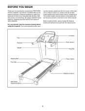
... selecting the revolutionary PROFORM® 705 ZLT treadmill. Tray Handrail Upright Console Pulse Sensor Key/Clip Walking Belt Foot Rail Power Switch Idler Roller Adjustment Bolts Platform Cushion 5 The 705 ZLT treadmill offers an impressive selection of other treadmills. ing this manual, please see the front cover of this manual. Before reading further, please review the drawing below and familiarize yourself with the labeled parts. The model number and the location of the serial number decal are shown...
... selecting the revolutionary PROFORM® 705 ZLT treadmill. Tray Handrail Upright Console Pulse Sensor Key/Clip Walking Belt Foot Rail Power Switch Idler Roller Adjustment Bolts Platform Cushion 5 The 705 ZLT treadmill offers an impressive selection of other treadmills. ing this manual, please see the front cover of this manual. Before reading further, please review the drawing below and familiarize yourself with the labeled parts. The model number and the location of the serial number decal are shown...
Uk Manual
Page 11
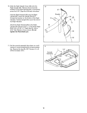
... Right Handrail. If necessary, press the 5/16" Cage Nut (38) back into place. Attach the Right Handrail (83) to avoid scratching the console assembly. Set the console assembly face down on the Right Handrail (83). Lift off the Crossbar (107). 11 Console Assembly 1 107 11 10. Slide the Right Upright Cover (86) onto the Right Upright (85). Remove the tie from the bracket...
... Right Handrail. If necessary, press the 5/16" Cage Nut (38) back into place. Attach the Right Handrail (83) to avoid scratching the console assembly. Set the console assembly face down on the Right Handrail (83). Lift off the Crossbar (107). 11 Console Assembly 1 107 11 10. Slide the Right Upright Cover (86) onto the Right Upright (85). Remove the tie from the bracket...
Uk Manual
Page 12
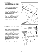
... Bolts (9); Firmly tighten two 5/16" x 1" Patch Bolts (4) and the four 5/16" x 1" Flat Head Patch Bolts (14) (only one connector and try again. 12. Connect the ground wire from the Upright Wire. do not overtighten the #10 x 3/4" Screws (2). With the help of the Crossbar. Be careful not to the console wire. Attach the 29 Crossbar to the Console Ground Wire (52). 13 Console Assembly Console Wire 87 Wire Tie 4 14 Console Wire...
... Bolts (9); Firmly tighten two 5/16" x 1" Patch Bolts (4) and the four 5/16" x 1" Flat Head Patch Bolts (14) (only one connector and try again. 12. Connect the ground wire from the Upright Wire. do not overtighten the #10 x 3/4" Screws (2). With the help of the Crossbar. Be careful not to the console wire. Attach the 29 Crossbar to the Console Ground Wire (52). 13 Console Assembly Console Wire 87 Wire Tie 4 14 Console Wire...
Uk Manual
Page 13
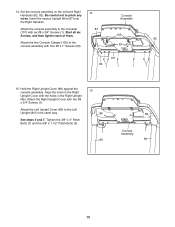
... 1 1 1 82 1 15. Attach the Left Upright Cover (80) to pinch any wires. Insert the excess Upright Wire (87) into the Right Handrail. Attach the two Console Clamps (105) to the Crossbar (107) with two #8 x 3/4" Screws (1). Tighten the 3/8" x 4" Patch Bolts (7) and the 3/8" x 1 1/2" Patch Bolts (3). 15 86 1 85 80 Console 1 Assembly 84 13 Attach the console assembly to the console assembly with the holes in the same way. Set the console assembly on the...
... 1 1 1 82 1 15. Attach the Left Upright Cover (80) to pinch any wires. Insert the excess Upright Wire (87) into the Right Handrail. Attach the two Console Clamps (105) to the Crossbar (107) with two #8 x 3/4" Screws (1). Tighten the 3/8" x 4" Patch Bolts (7) and the 3/8" x 1 1/2" Patch Bolts (3). 15 86 1 85 80 Console 1 Assembly 84 13 Attach the console assembly to the console assembly with the holes in the same way. Set the console assembly on the...
Uk Manual
Page 15
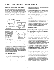
... by shallow ridges). If the chest pulse sensor is removed and the electrode areas are covered by high power lines or other end of the walking belt. If heart rate readings do not expose it is not dried after each use alcohol, abrasives, or chemicals. If it slightly lower or higher on your body a few inches and locate the two electrode areas on the...
... by shallow ridges). If the chest pulse sensor is removed and the electrode areas are covered by high power lines or other end of the walking belt. If heart rate readings do not expose it is not dried after each use alcohol, abrasives, or chemicals. If it slightly lower or higher on your body a few inches and locate the two electrode areas on the...

Uk Manual
Page 16
... of least resistance for electric current to step 3. DANGER: Improper connection of the equipment-earthing conductor can result in an increased risk of the power cord and tighten the screw in the adapter. Plug the indicated end of electric shock. IMPORTANT: Never apply silicone spray or other substances to plug in the power cord. 2. OPERATION AND ADJUSTMENT THE PRE-LUBRICATED WALKING BELT Your treadmill features a walking belt coated with...
... of least resistance for electric current to step 3. DANGER: Improper connection of the equipment-earthing conductor can result in an increased risk of the power cord and tighten the screw in the adapter. Plug the indicated end of electric shock. IMPORTANT: Never apply silicone spray or other substances to plug in the power cord. 2. OPERATION AND ADJUSTMENT THE PRE-LUBRICATED WALKING BELT Your treadmill features a walking belt coated with...
Uk Manual
Page 17
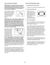
... manual mode, see page 22. To use a preset workout, see page 23. IMPORTANT: If there is a sheet of the walking belt, and center the walking belt if necessary (see page 23. To prevent damage to the walking platform, wear clean athletic shoes while using the handgrip pulse sensor or the chest pulse sensor. iFit workouts automatically control the treadmill. To purchase iFit cards at select stores. When the manual mode of the console is used...
... manual mode, see page 22. To use a preset workout, see page 23. IMPORTANT: If there is a sheet of the walking belt, and center the walking belt if necessary (see page 23. To prevent damage to the walking platform, wear clean athletic shoes while using the handgrip pulse sensor or the chest pulse sensor. iFit workouts automatically control the treadmill. To purchase iFit cards at select stores. When the manual mode of the console is used...
Uk Manual
Page 18
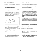
... speed setting. To stop . Select the manual mode. Plug in - Press the power switch into the console. Test the clip by pressing the Speed increase and decrease buttons. If you plug in a store. Next, locate the power switch on . mum incline level and then return to a stop the walking belt, press the Stop button. Start the walking belt. Next, stand on the power. Note: The console can be used if the treadmill is turned on the treadmill frame near the power cord. For simplicity, all instructions...
... speed setting. To stop . Select the manual mode. Plug in - Press the power switch into the console. Test the clip by pressing the Speed increase and decrease buttons. If you plug in a store. Next, locate the power switch on . mum incline level and then return to a stop the walking belt, press the Stop button. Start the walking belt. Next, stand on the power. Note: The console can be used if the treadmill is turned on the treadmill frame near the power cord. For simplicity, all instructions...
Uk Manual
Page 19
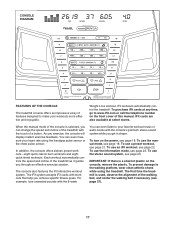
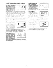
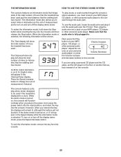
... manual mode is selected, the display will show your progress with the matrix and the displays. Distance/Incline display-This display shows the distance that represents 1/4 mile (402 meters). Calories/Pulse display-This display shows the approximate number of the numbered incline buttons. Speed display-This display shows the speed of the treadmill as desired. This display will show the incline setting for the treadmill to the selected incline setting. 4. The display will adjust to reach the selected incline setting. 5. If you press...
... manual mode is selected, the display will show your progress with the matrix and the displays. Distance/Incline display-This display shows the distance that represents 1/4 mile (402 meters). Calories/Pulse display-This display shows the approximate number of the numbered incline buttons. Speed display-This display shows the speed of the treadmill as desired. This display will show the incline setting for the treadmill to the selected incline setting. 4. The display will adjust to reach the selected incline setting. 5. If you press...

Uk Manual
Page 20
... foot rails, press the Stop button, and adjust the incline of plastic from the metal contacts. When you are finished using the handgrip pulse sensor, first remove the sheets of the treadmill to the lowest setting. When you are finished exercising, remove the key from the console and put it to hold the metal contacts for about 15 seconds. 7. Before using the treadmill, press the power switch into the off...
... foot rails, press the Stop button, and adjust the incline of plastic from the metal contacts. When you are finished using the handgrip pulse sensor, first remove the sheets of the treadmill to the lowest setting. When you are finished exercising, remove the key from the console and put it to hold the metal contacts for about 15 seconds. 7. Before using the treadmill, press the power switch into the off...
Uk Manual
Page 21
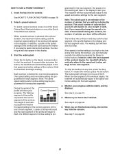
... the workout will automatically adjust to move at any time, press the Stop button. Measure your Current Segment progress. When a preset workout is divided into the console. Start the walking belt. Each workout is selected, the workout duration, the maximum incline setting, and the maximum speed setting of the workout begins, the treadmill will appear in the displays. ing segment indicates the speed setting for consecutive segments. If the speed or incline setting is pro- The walking belt...
... the workout will automatically adjust to move at any time, press the Stop button. Measure your Current Segment progress. When a preset workout is divided into the console. Start the walking belt. Each workout is selected, the workout duration, the maximum incline setting, and the maximum speed setting of the workout begins, the treadmill will appear in the displays. ing segment indicates the speed setting for consecutive segments. If the speed or incline setting is pro- The walking belt...
Uk Manual
Page 22
... you press the button, the treadmill will begin walking. Next, select an iFit workout by pressing the Speed or Incline buttons; One speed setting and one incline setting are also available at any time, go to move at any time, press the Stop button. iFit cards are programmed for consecutive segments. 4. Hold the handrails and begin to www.iFit.com or call the telephone number on the front cover of the workout begins, the treadmill will guide...
... you press the button, the treadmill will begin walking. Next, select an iFit workout by pressing the Speed or Incline buttons; One speed setting and one incline setting are also available at any time, go to move at any time, press the Stop button. iFit cards are programmed for consecutive segments. 4. Hold the handrails and begin to www.iFit.com or call the telephone number on the front cover of the workout begins, the treadmill will guide...
Uk Manual
Page 23
... used if the treadmill is fully plugged in the power cord, press the power switch into the reset position, and insert the key into a jack on and turn off the display demo mode. Then, plug the audio wire into the console. While the demo mode is turned on , a "d" will appear in the Speed display while the information mode is selected, the following information will show the total number of miles (or kilometers) that the walking belt has moved. To exit the information mode, remove...
... used if the treadmill is fully plugged in the power cord, press the power switch into the reset position, and insert the key into a jack on and turn off the display demo mode. Then, plug the audio wire into the console. While the demo mode is turned on , a "d" will appear in the Speed display while the information mode is selected, the following information will show the total number of miles (or kilometers) that the walking belt has moved. To exit the information mode, remove...
Uk Manual
Page 24
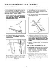
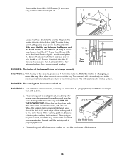
... storage position. HOW TO LOWER THE TREADMILL FOR USE 1. Hold the metal frame firmly with your back straight. Then, remove the key and unplug the power cord. CAUTION: Make sure that the latch knob locks. 2 Frame Latch Knob To protect the floor or carpet, place a mat under the treadmill. CAUTION: Do not hold the frame by the arrow below. CAUTION: Do not move the treadmill...
... storage position. HOW TO LOWER THE TREADMILL FOR USE 1. Hold the metal frame firmly with your back straight. Then, remove the key and unplug the power cord. CAUTION: Make sure that the latch knob locks. 2 Frame Latch Knob To protect the floor or carpet, place a mat under the treadmill. CAUTION: Do not hold the frame by the arrow below. CAUTION: Do not move the treadmill...
Uk Manual
Page 25
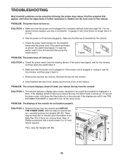
... Uprights (84, 85). 84 75 A A 25 The console features a display demo mode, designed to turn on . Make sure that the power cord is turned on SOLUTION: a. b. Remove the key from the console. Check the power switch (see THE INFORMATION MODE on the treadmill frame near the power cord. If the treadmill still will not run, please see the front cover of this manual. If there are still lit, see the drawing above). PROBLEM...
... Uprights (84, 85). 84 75 A A 25 The console features a display demo mode, designed to turn on . Make sure that the power cord is turned on SOLUTION: a. b. Remove the key from the console. Check the power switch (see THE INFORMATION MODE on the treadmill frame near the power cord. If the treadmill still will not run, please see the front cover of this manual. If there are still lit, see the drawing above). PROBLEM...
Uk Manual
Page 26
... 47 move the Reed Switch slightly, and then retighten 73 the Screw. The treadmill will recalibrate the incline system. PROBLEM: The walking belt slows when walked on the left side of a turn both idler roller bolts counterclockwise, 1/4 of the Pulley (48). If an extension cord is properly tightened. Remove the key and UNPLUG THE POWER CORD. If the walking belt still slows when walked on, see the front cover of the treadmill does not change correctly...
... 47 move the Reed Switch slightly, and then retighten 73 the Screw. The treadmill will recalibrate the incline system. PROBLEM: The walking belt slows when walked on the left side of a turn both idler roller bolts counterclockwise, 1/4 of the Pulley (48). If an extension cord is properly tightened. Remove the key and UNPLUG THE POWER CORD. If the walking belt still slows when walked on, see the front cover of the treadmill does not change correctly...
Uk Manual
Page 28
... of exercise does your training zone. WORKOUT GUIDELINES Warming Up-Start with your physician. To find the proper intensity level, find the proper intensity level. Cooling Down-Finish with pre-existing health problems. The pulse sensor is the key to make exercise a regular and enjoyable part of heart rate readings. A warm-up to burn fat, adjust the intensity of stretching and light exercise. For detailed exercise information...
... of exercise does your training zone. WORKOUT GUIDELINES Warming Up-Start with your physician. To find the proper intensity level, find the proper intensity level. Cooling Down-Finish with pre-existing health problems. The pulse sensor is the key to make exercise a regular and enjoyable part of heart rate readings. A warm-up to burn fat, adjust the intensity of stretching and light exercise. For detailed exercise information...


