
Uk Manual
Page 1
..., LS11 8JG UK CAUTION Read all precautions and instructions in the space above for future reference. PFEVEX71708.0 Serial No. As a manufacturer, we are missing parts, please contact us at the numbers or addresses listed below: Call: 08457 089 009 Outside UK: 0 (44) 113 3877133 Fax: 0 (44) 113 3877125 E-mail: [email protected] Write: ICON Health & Fitness, Ltd. Serial Number Decal QUESTIONS?
..., LS11 8JG UK CAUTION Read all precautions and instructions in the space above for future reference. PFEVEX71708.0 Serial No. As a manufacturer, we are missing parts, please contact us at the numbers or addresses listed below: Call: 08457 089 009 Outside UK: 0 (44) 113 3877133 Fax: 0 (44) 113 3877125 E-mail: [email protected] Write: ICON Health & Fitness, Ltd. Serial Number Decal QUESTIONS?

Uk Manual
Page 2
... instructions. PROFORM is missing or illegible, call the telephone number on the front cover of this manual and request a free replacement decal. User weight must not exceed 250 pounds. Replace label if damaged, illegible, or removed. TABLE OF CONTENTS WARNING DECAL PLACEMENT 2 IMPORTANT PRECAUTIONS 3 BEFORE YOU BEGIN 4 ASSEMBLY 5 HOW TO USE THE EXERCISE CYCLE 11 MAINTENANCE AND TROUBLESHOOTING 15 EXERCISE GUIDELINES 16 PART LIST 18 EXPLODED DRAWING 19 ORDERING REPLACEMENT PARTS...
... instructions. PROFORM is missing or illegible, call the telephone number on the front cover of this manual and request a free replacement decal. User weight must not exceed 250 pounds. Replace label if damaged, illegible, or removed. TABLE OF CONTENTS WARNING DECAL PLACEMENT 2 IMPORTANT PRECAUTIONS 3 BEFORE YOU BEGIN 4 ASSEMBLY 5 HOW TO USE THE EXERCISE CYCLE 11 MAINTENANCE AND TROUBLESHOOTING 15 EXERCISE GUIDELINES 16 PART LIST 18 EXPLODED DRAWING 19 ORDERING REPLACEMENT PARTS...

Uk Manual
Page 3
... while exercising, stop . 13. Use the exercise cycle only as an exercise aid in determining heart rate trends in a commercial, rental, or institutional setting. 4. Keep the exercise cycle indoors, away from the exercise cycle at all parts regularly. The pulse sensor is intended for foot protection while exercising. 9. Keep your exercise cycle. Before beginning any worn parts immediately. 6. When adjusting the height of the seat, insert the seat post knob...
... while exercising, stop . 13. Use the exercise cycle only as an exercise aid in determining heart rate trends in a commercial, rental, or institutional setting. 4. Keep the exercise cycle indoors, away from the exercise cycle at all parts regularly. The pulse sensor is intended for foot protection while exercising. 9. Keep your exercise cycle. Before beginning any worn parts immediately. 6. When adjusting the height of the seat, insert the seat post knob...

Uk Manual
Page 4
... Seat Seat Knob Seat Post Seat Post Knob Console Pulse Sensor Pedal/Strap Leveling Cap 4 The 700 exercise cycle offers a selection of features designed to let you enjoy this healthful exercise in the drawing below. Cycling is one of your benefit, read this manual carefully before contacting us. If you , note the product model number and serial number before you use the exercise cycle. Before reading further, please familiarize yourself with the parts...
... Seat Seat Knob Seat Post Seat Post Knob Console Pulse Sensor Pedal/Strap Leveling Cap 4 The 700 exercise cycle offers a selection of features designed to let you enjoy this healthful exercise in the drawing below. Cycling is one of your benefit, read this manual carefully before contacting us. If you , note the product model number and serial number before you use the exercise cycle. Before reading further, please familiarize yourself with the parts...
Uk Manual
Page 5
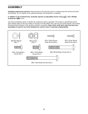
... not dispose of this manual. Note: Some small parts may have been preassembled. The number in assembly. In addition to identify the small parts used in parentheses below to the included tools, assembly requires an adjustable wrench screwdriver . Place all parts of the exercise cycle in the hardware kit, check to the key number of the part, from the PART LIST near the end of...
... not dispose of this manual. Note: Some small parts may have been preassembled. The number in assembly. In addition to identify the small parts used in parentheses below to the included tools, assembly requires an adjustable wrench screwdriver . Place all parts of the exercise cycle in the hardware kit, check to the key number of the part, from the PART LIST near the end of...

Uk Manual
Page 6
Attach the Front Stabilizer (2) to the Frame (1) with four M8 x 60mm Button Screws (30). 2. Orient the Front Stabilizer (2) so that the large holes are facing the Frame (1). Attach the Rear Stabilizer with two M8 x 73mm Button Screws (33). 2 33 1 6 30 2 Large Holes 1 6 Insert the Rear Stabilizer (6) into the Frame (1). 1. To make assembly easier, read the 1 information on page 5 before you begin assembling the exercise cycle.
Attach the Front Stabilizer (2) to the Frame (1) with four M8 x 60mm Button Screws (30). 2. Orient the Front Stabilizer (2) so that the large holes are facing the Frame (1). Attach the Rear Stabilizer with two M8 x 73mm Button Screws (33). 2 33 1 6 30 2 Large Holes 1 6 Insert the Rear Stabilizer (6) into the Frame (1). 1. To make assembly easier, read the 1 information on page 5 before you begin assembling the exercise cycle.

Uk Manual
Page 7
...15mm 3 Round Head Screw (58) and two M5 x 15mm Round Head Screws (59). 19 58 59 4. Next, insert the Seat Knob (56) upward through the bracket on the Seat Post (5). Set the Seat Carriage (29) in the bracket on the Seat Post into the hole in the Seat Block. 12 42 ...10 5 3 59 1 44 29 42 10 56 7 Make sure the Seat Knob is engaged in the hole in the Seat Block (44). Attach the Seat (12) to the underside of the Seat. Then, tighten the Seat Knob. Attach the Left and Right Frame Covers...
...15mm 3 Round Head Screw (58) and two M5 x 15mm Round Head Screws (59). 19 58 59 4. Next, insert the Seat Knob (56) upward through the bracket on the Seat Post (5). Set the Seat Carriage (29) in the bracket on the Seat Post into the hole in the Seat Block. 12 42 ...10 5 3 59 1 44 29 42 10 56 7 Make sure the Seat Knob is engaged in the hole in the Seat Block (44). Attach the Seat (12) to the underside of the Seat. Then, tighten the Seat Knob. Attach the Left and Right Frame Covers...

Uk Manual
Page 8
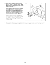
..., tighten the Seat Post Knob. Attach the Upright (13) with three M8 x 15mm Button Screws (34) and three M8 Split Washers (42). 13 Avoid pinching the wires 34 42 23 39 42 34 1 8 Adjustment Holes 5 1 Hole 9 6. Tip: Avoid pinching the wires. Adjust the Seat Post to the Reed Switch Wire (39). Make sure the Seat Post Knob is firmly engaged in one of the adjustment holes in the Seat...
..., tighten the Seat Post Knob. Attach the Upright (13) with three M8 x 15mm Button Screws (34) and three M8 Split Washers (42). 13 Avoid pinching the wires 34 42 23 39 42 34 1 8 Adjustment Holes 5 1 Hole 9 6. Tip: Avoid pinching the wires. Adjust the Seat Post to the Reed Switch Wire (39). Make sure the Seat Post Knob is firmly engaged in one of the adjustment holes in the Seat...

Uk Manual
Page 9
...) near the Upright (13), insert the console wire through the Pivot Bracket (53) and connect it to warm to room temperature before inserting batteries. Then, insert the excess wire downward into the battery compartment, and reat- Battery Cover Batteries 16 8. The Console (16) can use four AA batteries (not included); Otherwise, you may damage the console displays or other electronic compo- tach the battery cover. Attach the Left...
...) near the Upright (13), insert the console wire through the Pivot Bracket (53) and connect it to warm to room temperature before inserting batteries. Then, insert the excess wire downward into the battery compartment, and reat- Battery Cover Batteries 16 8. The Console (16) can use four AA batteries (not included); Otherwise, you may damage the console displays or other electronic compo- tach the battery cover. Attach the Left...
Uk Manual
Page 10
... the Crank (not shown). Adjust the strap on the side of the Crank (21). After using the exercise cycle for one week, retighten the pedals. Make sure that all parts are properly tightened before you use the exercise cycle. Tighten the Right Pedal (not shown) clockwise into the left over. Identify the Left Pedal (24), which is completed, some extra parts may be left arm of...
... the Crank (not shown). Adjust the strap on the side of the Crank (21). After using the exercise cycle for one week, retighten the pedals. Make sure that all parts are properly tightened before you use the exercise cycle. Tighten the Right Pedal (not shown) clockwise into the left over. Identify the Left Pedal (24), which is completed, some extra parts may be left arm of...

Uk Manual
Page 11
.... As you pedal, there should be a slight bend in your floor during use, turn it clockwise again. Insert the seat post knob into the frame and the seat post, and tighten the seat post knob. Note: The pivot handle func- Turn the pivot handle clockwise, pull it away from the upright, turn it counterclockwise, push it toward the upright, and then turn one of...
.... As you pedal, there should be a slight bend in your floor during use, turn it clockwise again. Insert the seat post knob into the frame and the seat post, and tighten the seat post knob. Note: The pivot handle func- Turn the pivot handle clockwise, pull it away from the upright, turn it counterclockwise, push it toward the upright, and then turn one of...

Uk Manual
Page 12
... pulse sensor. The console has seven displays that show the following workout information: Speed-This display shows your heart rate using the console, make your heart rate when you use . Time-This display shows the elapsed time. Distance-This display shows the distance you have pedaled, in miles or kilometers per hour. Turn on the console, press the On/Reset button or begin pedaling. Pulse-This display shows your workouts more effective. CONSOLE DIAGRAM 2. If you have selected a program, reselect the manual mode by pressing the Resistance...
... pulse sensor. The console has seven displays that show the following workout information: Speed-This display shows your heart rate using the console, make your heart rate when you use . Time-This display shows the elapsed time. Distance-This display shows the distance you have pedaled, in miles or kilometers per hour. Turn on the console, press the On/Reset button or begin pedaling. Pulse-This display shows your workouts more effective. CONSOLE DIAGRAM 2. If you have selected a program, reselect the manual mode by pressing the Resistance...

Uk Manual
Page 13
... your heart rate, hold the handgrip pulse sensor, the display will disappear. If the pedals do not move your heart rate will appear. The indicator below the word SCAN. To continue your hands or gripping the contacts tightly. Note: If there are finished exercising, the console will flash in the display to show your pedaling speed. vide a visual rep- To reset the display, press the On/Reset button. After...
... your heart rate, hold the handgrip pulse sensor, the display will disappear. If the pedals do not move your heart rate will appear. The indicator below the word SCAN. To continue your hands or gripping the contacts tightly. Note: If there are finished exercising, the console will flash in the display to show your pedaling speed. vide a visual rep- To reset the display, press the On/Reset button. After...
Uk Manual
Page 14
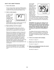
... same number of 20 or 30 oneminute segments. See step 6 on page 13. 6. A few seconds, the program will pause and the time will turn on the console, press the On/Reset button or begin pedaling. See step 4 on the console. One resistance level and one target pace are finished exercising, the console will flash in the program. The smart programs consist of bars appears in the display. Turn on...
... same number of 20 or 30 oneminute segments. See step 6 on page 13. 6. A few seconds, the program will pause and the time will turn on the console, press the On/Reset button or begin pedaling. See step 4 on the console. One resistance level and one target pace are finished exercising, the console will flash in the program. The smart programs consist of bars appears in the display. Turn on...

Uk Manual
Page 15
... the exercise cycle regularly. MAINTENANCE AND TROUBLESHOOTING Inspect and tighten all parts of mild detergent. Finally, tighten the 3/8" Nuts and reattach the shields, the frame covers, the upright covers, and the pedals. 38 39 47 21 Locate the Reed Switch (39). BATTERY REPLACEMENT If the console display becomes dim, the batteries should be adjusted. To adjust the reed switch, the left pedal, the upright covers, the frame covers, and the left pedal. Then, carefully remove the upright covers, the frame covers...
... the exercise cycle regularly. MAINTENANCE AND TROUBLESHOOTING Inspect and tighten all parts of mild detergent. Finally, tighten the 3/8" Nuts and reattach the shields, the frame covers, the upright covers, and the pedals. 38 39 47 21 Locate the Reed Switch (39). BATTERY REPLACEMENT If the console display becomes dim, the batteries should be adjusted. To adjust the reed switch, the left pedal, the upright covers, the frame covers, and the left pedal. Then, carefully remove the upright covers, the frame covers...

Uk Manual
Page 16
... your heart rate in your training zone for longer than 20 minutes.) Breathe regularly and deeply as a guide to plan your body uses carbohydrate calories for 20 to 30 minutes with pre-existing health problems. The pulse sensor is near the middle number in general. For detailed exercise information, obtain a reputable book or consult your "training zone." EXERCISE GUIDELINES WARNING: Before beginning this or any exercise program...
... your heart rate in your training zone for longer than 20 minutes.) Breathe regularly and deeply as a guide to plan your body uses carbohydrate calories for 20 to 30 minutes with pre-existing health problems. The pulse sensor is near the middle number in general. For detailed exercise information, obtain a reputable book or consult your "training zone." EXERCISE GUIDELINES WARNING: Before beginning this or any exercise program...

Uk Manual
Page 17
SUGGESTED STRETCHES The correct form for 15 counts, then relax. Hold for several basic stretches...and hip muscles. 1 2 4 17 Reach toward your toes as far as possible. Repeat 3 times for each leg. Hold for each leg. Pull your feet toward your groin area as far as possible. Bring the sole of the opposite foot toward your... hands against a wall. Stretches: Hamstrings, lower back and groin. 3. Bend your front leg, lean forward and move your back foot flat on the floor. Stretches: Calves, achilles tendons and ankles. 4....
SUGGESTED STRETCHES The correct form for 15 counts, then relax. Hold for several basic stretches...and hip muscles. 1 2 4 17 Reach toward your toes as far as possible. Repeat 3 times for each leg. Hold for each leg. Pull your feet toward your groin area as far as possible. Bring the sole of the opposite foot toward your... hands against a wall. Stretches: Hamstrings, lower back and groin. 3. Bend your front leg, lean forward and move your back foot flat on the floor. Stretches: Calves, achilles tendons and ankles. 4....
Uk Manual
Page 18
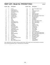
... 1 Left Pivot Cover 51 1 Right Pivot Cover 52 1 Upright Plug 53 1 Pivot Bracket 54 1 Pivot Clamp 55 1 Pivot Handle 56 1 Seat Knob 57 2 Seat Carriage Cap 58 2 M4 x 15mm Round Head Screw 59 4 M5 x 15mm Round Head Screw 60 1 Resistance Motor 61 4 M5 x 12mm Screw 62 1 Resistance Cable 63 1 Wire Harness 64 1 Handlebar * - PART LIST-Model No. Qty. Qty. Userʼs Manual * - Assembly Tool Note: Specifications are not illustrated. 18 PFEVEX71708.0 R0808A Key No.
... 1 Left Pivot Cover 51 1 Right Pivot Cover 52 1 Upright Plug 53 1 Pivot Bracket 54 1 Pivot Clamp 55 1 Pivot Handle 56 1 Seat Knob 57 2 Seat Carriage Cap 58 2 M4 x 15mm Round Head Screw 59 4 M5 x 15mm Round Head Screw 60 1 Resistance Motor 61 4 M5 x 12mm Screw 62 1 Resistance Cable 63 1 Wire Harness 64 1 Handlebar * - PART LIST-Model No. Qty. Qty. Userʼs Manual * - Assembly Tool Note: Specifications are not illustrated. 18 PFEVEX71708.0 R0808A Key No.

Uk Manual
Page 19
PFEVEX71708.0 R0808A 7 7 16 46 51 64 50 59 59 52 58 53 18 54 12 41 41 41 41 26 41 14 33 2 4 24 41 15 42 34 4 1 17 55 13 23 5 42 34 57 56 42 10 44 29 57 42 38 10 42 10 63 20 36 47 22 39 61 60 9 40 11 45 25 49 27 31 28 32 43 62 21 43 27 32 31 28 37 41 41 41 35 30 8 48 8 6 19 3 59 58 48 59 19 EXPLODED DRAWING-Model No.
PFEVEX71708.0 R0808A 7 7 16 46 51 64 50 59 59 52 58 53 18 54 12 41 41 41 41 26 41 14 33 2 4 24 41 15 42 34 4 1 17 55 13 23 5 42 34 57 56 42 10 44 29 57 42 38 10 42 10 63 20 36 47 22 39 61 60 9 40 11 45 25 49 27 31 28 32 43 62 21 43 27 32 31 28 37 41 41 41 35 30 8 48 8 6 19 3 59 58 48 59 19 EXPLODED DRAWING-Model No.

Uk Manual
Page 20
To help us assist you, be prepared to provide the following information when contacting us: • the model number and serial number of the product (see the front cover of this manual) • the name of the product (see the front cover of this manual) • the key number and description of the replacement part(s) (see the front cover of this manual. ORDERING REPLACEMENT PARTS To order replacement parts, please see the PART LIST and the EXPLODED DRAWING near the end of this manual) Part No. 270744 R0808A Printed in China © 2008 ICON IP, Inc.
To help us assist you, be prepared to provide the following information when contacting us: • the model number and serial number of the product (see the front cover of this manual) • the name of the product (see the front cover of this manual) • the key number and description of the replacement part(s) (see the front cover of this manual. ORDERING REPLACEMENT PARTS To order replacement parts, please see the PART LIST and the EXPLODED DRAWING near the end of this manual) Part No. 270744 R0808A Printed in China © 2008 ICON IP, Inc.

