

English Manual
Page 1
.... MST CAUTION Read all precautions and instructions in the space above for future reference. Write the serial number in this manual before using this manual for reference. ¨ USERÕS MANUAL Serial Number Decal (under seat) QUESTIONS? If you have questions, or find that there are missing or damaged parts, we are committed to you complete satisfaction through direct assistance from our factory. CUSTOMER...
.... MST CAUTION Read all precautions and instructions in the space above for future reference. Write the serial number in this manual before using this manual for reference. ¨ USERÕS MANUAL Serial Number Decal (under seat) QUESTIONS? If you have questions, or find that there are missing or damaged parts, we are committed to you complete satisfaction through direct assistance from our factory. CUSTOMER...
English Manual
Page 2
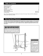
... Begin 4 Part Identification Chart 5 Assembly 6 Adjusting the Weight Bench 15 Exercise Guidelines 17 Ordering Replacement Parts Back Cover Limited Warranty Back Cover Note: A Part List/Exploded Drawing is not legible, please call our Customer Service Department toll-free at 1-800-999-3756, Monday through Friday, 6 a.m. Apply the replacement decal to order a replacement decal. Table of this manual. Mountain Time, to the location shown. ! ! 2 until 6 p.m. Remove the Part List/Exploded Drawing before beginning assembly. Warning Decal...
... Begin 4 Part Identification Chart 5 Assembly 6 Adjusting the Weight Bench 15 Exercise Guidelines 17 Ordering Replacement Parts Back Cover Limited Warranty Back Cover Note: A Part List/Exploded Drawing is not legible, please call our Customer Service Department toll-free at 1-800-999-3756, Monday through Friday, 6 a.m. Apply the replacement decal to order a replacement decal. Table of this manual. Mountain Time, to the location shown. ! ! 2 until 6 p.m. Remove the Part List/Exploded Drawing before beginning assembly. Warning Decal...
English Manual
Page 3
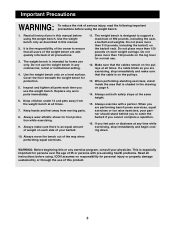
... from moving parts. 8. This is on the pulleys at any exercise program, consult your barbell. 11. ICON assumes no responsibility for protection. 5. Read all times. Keep hands and feet away from the weight bench at the same height. 15. The weight bench is shaded in this manual before using the weight bench. 1. Always set both safety stops at all parts each time you are performing bench press exercises, squat exercises or...
... from moving parts. 8. This is on the pulleys at any exercise program, consult your barbell. 11. ICON assumes no responsibility for protection. 5. Read all times. Keep hands and feet away from the weight bench at the same height. 15. The weight bench is shaded in this manual before using the weight bench. 1. Always set both safety stops at all parts each time you are performing bench press exercises, squat exercises or...

English Manual
Page 4
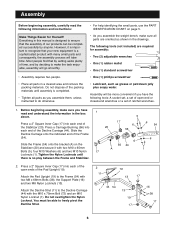
... Safety Stop Backrest Seat Weight Carriage Low Pulley 4 The PROFORM¨ 660 is designed to the PROFORM¨ 660 Weight Bench (see the front cover of the body. Monday through Friday, 6 a.m. Before You Begin Thank you have additional questions, please call our Customer Service Department toll-free at 1-800-999-3756, Before reading further, please review the drawing below and familiarize yourself with the parts that...
... Safety Stop Backrest Seat Weight Carriage Low Pulley 4 The PROFORM¨ 660 is designed to the PROFORM¨ 660 Weight Bench (see the front cover of the body. Monday through Friday, 6 a.m. Before You Begin Thank you have additional questions, please call our Customer Service Department toll-free at 1-800-999-3756, Before reading further, please review the drawing below and familiarize yourself with the parts that...

English Manual
Page 5
... Bolt (38) M10 x 72mm Bolt (59) M8 x 62mm Bolt (58) M10 x 75mm Bolt (72) M8 x 41mm Bolt (34) M10 x 93mm Bolt (43) M8 x 14mm Screw (30) Plastic Washer (21)-4 M10 Washer (6) Thin M8 Washer (22) M6 Washer (68) 1/2" Spacer (50) M8 Spacer (66) M6 Nylon Locknut (2) M8 Nylon Locknut (13) M10 Nylon Locknut (1) 5 1/2" Nylon Locknut (60) Part Identification Chart...
... Bolt (38) M10 x 72mm Bolt (59) M8 x 62mm Bolt (58) M10 x 75mm Bolt (72) M8 x 41mm Bolt (34) M10 x 93mm Bolt (43) M8 x 14mm Screw (30) Plastic Washer (21)-4 M10 Washer (6) Thin M8 Washer (22) M6 Washer (68) 1/2" Spacer (50) M8 Spacer (66) M6 Nylon Locknut (2) M8 Nylon Locknut (13) M10 Nylon Locknut (1) 5 1/2" Nylon Locknut (60) Part Identification Chart...
English Manual
Page 6
... Locknuts until assembly is completed. ¥ Tighten all parts as you assemble them, unless instructed to do otherwise. ¥ For help identifying the small parts, use the PART IDENTIFICATION CHART on the Stabilizer (20) and secure it is a sophisticated product with two M8 x 68mm Bolts (38), the Support Plate (16) and two M8 Nylon Locknuts (13). Attach the Decline Strut (11) to...
... Locknuts until assembly is completed. ¥ Tighten all parts as you assemble them, unless instructed to do otherwise. ¥ For help identifying the small parts, use the PART IDENTIFICATION CHART on the Stabilizer (20) and secure it is a sophisticated product with two M8 x 68mm Bolts (38), the Support Plate (16) and two M8 Nylon Locknuts (13). Attach the Decline Strut (11) to...
English Manual
Page 7
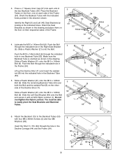
...Bolt (8). Attach the Backrest (15) to easily pivot the Seat Brackets and Backrest Tubes. 53 21 B 54 B 21 8 46 Holes 9 8 9 6. 3. Lubricate the M10 x 145mm Bolt (8). Insert the Short ÒLÓ-Pin (63) through the indicated hole in the Backrest Tube (53). 5. Orient the Seat Brackets as shown in the direction... Strut (11). 53 Slide a Plastic Washer (21) onto the M10 x 145mm Bolt (8). Slide the Left Seat Bracket (46) onto the Bolt and secure it with four M6 x 38mm Screws (4) and four M6 Washers (68). Orient the Backrest Tubes with the indicated holes pointed...
...Bolt (8). Attach the Backrest (15) to easily pivot the Seat Brackets and Backrest Tubes. 53 21 B 54 B 21 8 46 Holes 9 8 9 6. 3. Lubricate the M10 x 145mm Bolt (8). Insert the Short ÒLÓ-Pin (63) through the indicated hole in the Backrest Tube (53). 5. Orient the Seat Brackets as shown in the direction... Strut (11). 53 Slide a Plastic Washer (21) onto the M10 x 145mm Bolt (8). Slide the Left Seat Bracket (46) onto the Bolt and secure it with four M6 x 38mm Screws (4) and four M6 Washers (68). Orient the Backrest Tubes with the indicated holes pointed...
English Manual
Page 8
... each of the open ends of the Short Pad Tube. Press a 2Ó Square Inner Cap (17) into each end of 10 the three Pad Tubes (67, 77). Press a 1Ó Round Inner Cap (12) into the lower hole in the 10 bracket (C) on the Pad Upright (19) with 7 four M6 x 16mm Screws (3) and four ... bracket (C) on the Pad Upright (19). Attach the Leg Lever (18) to the Pad Upright (19) with an M6 x 32mm Bolt (7) and an M6 Nylon Locknut (2). Attach the Seat (14) to mount the Weight Adapter. 8 49 22 50 13 71 68 3 3 17 18 17 52 22 7 47 48 47 17 51 2 12 9. Press the Angle Cap (49) ...
... each of the open ends of the Short Pad Tube. Press a 2Ó Square Inner Cap (17) into each end of 10 the three Pad Tubes (67, 77). Press a 1Ó Round Inner Cap (12) into the lower hole in the 10 bracket (C) on the Pad Upright (19) with 7 four M6 x 16mm Screws (3) and four ... bracket (C) on the Pad Upright (19). Attach the Leg Lever (18) to the Pad Upright (19) with an M6 x 32mm Bolt (7) and an M6 Nylon Locknut (2). Attach the Seat (14) to mount the Weight Adapter. 8 49 22 50 13 71 68 3 3 17 18 17 52 22 7 47 48 47 17 51 2 12 9. Press the Angle Cap (49) ...

English Manual
Page 10
...assembled Barbell Rack (31) onto both Weight Uprights (42). ed with two M10 x 65mm Bolts (5), four M10 Washers (6) and two M10 Nylon Locknuts (1). Attach a Weight Upright (42) to the bracket (G) on the 13 Right Base (25) with the large holes facing inward exactly as shown. 6 5 41 61 6 5 6 42 6 1 6 G F 25 14. Repeat the above steps... for the Left Base (26, not shown). Make sure the Weight Uprights (41, 42) are orient- Slide a pre-assembled Weight Carriage (37) onto 14 both Barbell Uprights (41). 31 Make sure the Weight Uprights (41, 42)...
...assembled Barbell Rack (31) onto both Weight Uprights (42). ed with two M10 x 65mm Bolts (5), four M10 Washers (6) and two M10 Nylon Locknuts (1). Attach a Weight Upright (42) to the bracket (G) on the 13 Right Base (25) with the large holes facing inward exactly as shown. 6 5 41 61 6 5 6 42 6 1 6 G F 25 14. Repeat the above steps... for the Left Base (26, not shown). Make sure the Weight Uprights (41, 42) are orient- Slide a pre-assembled Weight Carriage (37) onto 14 both Barbell Uprights (41). 31 Make sure the Weight Uprights (41, 42)...

English Manual
Page 11
... on the Top Frame fit into each of the two holes, as shown. Make sure the Bolt is completed, tighten all Nylon Locknuts used in the same manner. Attach the Top Frame (24) to the right Weight Upright (42) and the right Barbell Upright (41) in the Base, the Uprights and the Top Frame (see steps 12, 15 and 17...
... on the Top Frame fit into each of the two holes, as shown. Make sure the Bolt is completed, tighten all Nylon Locknuts used in the same manner. Attach the Top Frame (24) to the right Weight Upright (42) and the right Barbell Upright (41) in the Base, the Uprights and the Top Frame (see steps 12, 15 and 17...

English Manual
Page 12
... x 39mm Bolt (39). Attach a Pulley Bracket (28) to the Pulley Bracket (28) on the Top Frame (24) and the Left Base (26). Wrap the Cable (45) around a 3 1/2Ó Pulley (35) in 19 the direction shown. The Bracket on the Left Base (26) must have the welded cable trap pointed downward. 17 Welded Cable Trap 28 60 24 Welded Bolt (Lubricate) 60...
... x 39mm Bolt (39). Attach a Pulley Bracket (28) to the Pulley Bracket (28) on the Top Frame (24) and the Left Base (26). Wrap the Cable (45) around a 3 1/2Ó Pulley (35) in 19 the direction shown. The Bracket on the Left Base (26) must have the welded cable trap pointed downward. 17 Welded Cable Trap 28 60 24 Welded Bolt (Lubricate) 60...

English Manual
Page 13
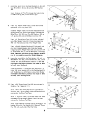
... turn the Barbell (74). 29 34 30 23 13 Slide one end of a Cable (45) around a 3 1/2Ó Pulley (35) in steps 20 to the right Weight Upright (42) with two M8 x 14mm Screws (30). Attach the Pulley to 23. 21 25 28 1 73 35 45 22. Then 74 press the U-shaped part of the two holes, as described in the 20 direction...
... turn the Barbell (74). 29 34 30 23 13 Slide one end of a Cable (45) around a 3 1/2Ó Pulley (35) in steps 20 to the right Weight Upright (42) with two M8 x 14mm Screws (30). Attach the Pulley to 23. 21 25 28 1 73 35 45 22. Then 74 press the U-shaped part of the two holes, as described in the 20 direction...
English Manual
Page 14
... the Barbell Hooks lock into each exercise. Press a Weight Adapter Bushing (47) into a set of holes in the Barbell Uprights (41) that exercise. The weight bench can be explained in Adjusting the Weight Bench starting on page 15. 74 7 61 2 47 47 Adjusting the Weight Bench This section explains how to use the weight bench. USING THE BARBELL RACKS Before beginning an exercise, move the Safety Stops (23) to get the most benefit...
... the Barbell Hooks lock into each exercise. Press a Weight Adapter Bushing (47) into a set of holes in the Barbell Uprights (41) that exercise. The weight bench can be explained in Adjusting the Weight Bench starting on page 15. 74 7 61 2 47 47 Adjusting the Weight Bench This section explains how to use the weight bench. USING THE BARBELL RACKS Before beginning an exercise, move the Safety Stops (23) to get the most benefit...

English Manual
Page 15
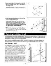
... in the Frame (54). ADJUSTING THE SEAT INCLINE Some exercises can be performed more than 150 pounds on the leg lever. 77 15 63 18 48 15 Lift up the end of the Backrest (15), pull out the Short ÒLÓ-Pin (63). See assembly step 8 for instructions on the backrest. ATTACHING WEIGHTS TO THE LEG LEVER To use a Weight Adapter (48). WARNING: Always insert...
... in the Frame (54). ADJUSTING THE SEAT INCLINE Some exercises can be performed more than 150 pounds on the leg lever. 77 15 63 18 48 15 Lift up the end of the Backrest (15), pull out the Short ÒLÓ-Pin (63). See assembly step 8 for instructions on the backrest. ATTACHING WEIGHTS TO THE LEG LEVER To use a Weight Adapter (48). WARNING: Always insert...

English Manual
Page 16
... AND LOWER PULLEY STATIONS A 45 To use the upper pulley station (see drawing A) or lower pulley station (see drawing B), weight must first be attached to the Cables (45) with the Cable Clips (64) as shown. 36 55 The Ankle Strap (55) can be placed 64 on both Weight Carriages. If you are using olympic weights, you will need to the Barbell (74), Weight Carriages (37) or Leg...
... AND LOWER PULLEY STATIONS A 45 To use the upper pulley station (see drawing A) or lower pulley station (see drawing B), weight must first be attached to the Cables (45) with the Cable Clips (64) as shown. 36 55 The Ankle Strap (55) can be placed 64 on both Weight Carriages. If you are using olympic weights, you will need to the Barbell (74), Weight Carriages (37) or Leg...
English Manual
Page 17
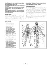
... should progress at any exercise program. Refer to the muscle chart on Monday, feeling exhausted. This requires moving only the appropriate parts of a balanced program is: ¥ Plan weight training workouts on page 18 to find the schedule that you find the locations of 30 seconds between sets. One example of the body. The exertion stage of each exercise and moving through the full...
... should progress at any exercise program. Refer to the muscle chart on Monday, feeling exhausted. This requires moving only the appropriate parts of a balanced program is: ¥ Plan weight training workouts on page 18 to find the schedule that you find the locations of 30 seconds between sets. One example of the body. The exertion stage of each exercise and moving through the full...
English Manual
Page 18
... used to make exercise a regular and enjoyable part of your weight and key body measurements at the end of each workout is very effective for a short period of this manual can without strain. Biceps (front of calf) K. Quadriceps (front of every month. Trapezius (upper back) H O. List the date, the exercises performed, the weight plus the numbers of arm) J R. Obliques (waist) B E. Ease into each set...
... used to make exercise a regular and enjoyable part of your weight and key body measurements at the end of each workout is very effective for a short period of this manual can without strain. Biceps (front of calf) K. Quadriceps (front of every month. Trapezius (upper back) H O. List the date, the exercises performed, the weight plus the numbers of arm) J R. Obliques (waist) B E. Ease into each set...
English Manual
Page 19
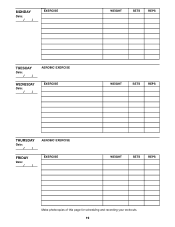
MONDAY Date: / / EXERCISE WEIGHT SETS REPS TUESDAY Date: / / WEDNESDAY Date: / / AEROBIC EXERCISE EXERCISE WEIGHT SETS REPS THURSDAY Date: / / FRIDAY Date: / / AEROBIC EXERCISE EXERCISE WEIGHT SETS REPS Make photocopies of this page for scheduling and recording your workouts. 19
MONDAY Date: / / EXERCISE WEIGHT SETS REPS TUESDAY Date: / / WEDNESDAY Date: / / AEROBIC EXERCISE EXERCISE WEIGHT SETS REPS THURSDAY Date: / / FRIDAY Date: / / AEROBIC EXERCISE EXERCISE WEIGHT SETS REPS Make photocopies of this page for scheduling and recording your workouts. 19
English Manual
Page 20
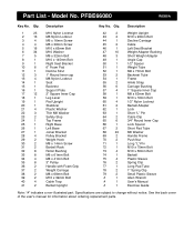
Model No. Qty. PFBE66080 R0200A Key No. Qty. Specifications are subject to change without notice. See the back cover of the userÕs manual for information about ordering replacement parts. Description 1 25 M10 Nylon Locknut 2 13 M6 Nylon Locknut 3 4 M6 x 16mm Screw 4 4 M6 x 38mm Screw 5 16 M10 x 65mm Bolt 6 34 M10 Washer 7 5 M6 x 32mm Bolt 8 1 M10 x 145mm Bolt 9 1 Right Seat Bracket 10 6 6Ó Foam Pad 11 1 Decline...
Model No. Qty. PFBE66080 R0200A Key No. Qty. Specifications are subject to change without notice. See the back cover of the userÕs manual for information about ordering replacement parts. Description 1 25 M10 Nylon Locknut 2 13 M6 Nylon Locknut 3 4 M6 x 16mm Screw 4 4 M6 x 38mm Screw 5 16 M10 x 65mm Bolt 6 34 M10 Washer 7 5 M6 x 32mm Bolt 8 1 M10 x 145mm Bolt 9 1 Right Seat Bracket 10 6 6Ó Foam Pad 11 1 Decline...

English Manual
Page 22
... warranties of this warranty is limited to replacing or repairing, at ICON's option, the product at one of the product (PFBE66080). 2. ICON HEALTH & FITNESS, INC., 1500 S. 1000 W., LOGAN, UT 84321-9813 PROFORM is limited in its authorized service centers with the use and service conditions, for a particular purpose is a registered trademark of this product to you specific legal rights. The KEY NUMBER and DESCRIPTION of the desired part...
... warranties of this warranty is limited to replacing or repairing, at ICON's option, the product at one of the product (PFBE66080). 2. ICON HEALTH & FITNESS, INC., 1500 S. 1000 W., LOGAN, UT 84321-9813 PROFORM is limited in its authorized service centers with the use and service conditions, for a particular purpose is a registered trademark of this product to you specific legal rights. The KEY NUMBER and DESCRIPTION of the desired part...


