
English Manual
Page 1
www.proform.com Model No. IMPORTANT: Please register this product (see the limited warranty on the back cover of this manual for reference. CALL TOLL-FREE: 1-888-533-1333 Mon.-Fri., 6 a.m.-6 p.m. Serial Number Decal (under frame) QUESTIONS? USER'S MANUAL Keep this manual) before using this equipment. MT Sat. 8 a.m.-4 p.m. MT ON THE WEB: www.proformservice.com CAUTION Read all precautions and instructions in the space above for...
www.proform.com Model No. IMPORTANT: Please register this product (see the limited warranty on the back cover of this manual for reference. CALL TOLL-FREE: 1-888-533-1333 Mon.-Fri., 6 a.m.-6 p.m. Serial Number Decal (under frame) QUESTIONS? USER'S MANUAL Keep this manual) before using this equipment. MT Sat. 8 a.m.-4 p.m. MT ON THE WEB: www.proformservice.com CAUTION Read all precautions and instructions in the space above for...

English Manual
Page 2
... CHART 5 ASSEMBLY 6 HOW TO USE THE EXERCISE BIKE 11 FCC INFORMATION 18 MAINTENANCE AND TROUBLESHOOTING 19 EXERCISE GUIDELINES 21 PART LIST 22 EXPLODED DRAWING 23 ORDERING REPLACEMENT PARTS Back Cover LIMITED WARRANTY Back Cover WARNING DECAL PLACEMENT This drawing shows the location(s) of ICON IP, Inc. 2 PROFORM is missing or illegible, see the front cover of this manual and request a free replacement decal. Note: The decal(s) may not be shown at actual size. If a decal...
... CHART 5 ASSEMBLY 6 HOW TO USE THE EXERCISE BIKE 11 FCC INFORMATION 18 MAINTENANCE AND TROUBLESHOOTING 19 EXERCISE GUIDELINES 21 PART LIST 22 EXPLODED DRAWING 23 ORDERING REPLACEMENT PARTS Back Cover LIMITED WARRANTY Back Cover WARNING DECAL PLACEMENT This drawing shows the location(s) of ICON IP, Inc. 2 PROFORM is missing or illegible, see the front cover of this manual and request a free replacement decal. Note: The decal(s) may not be shown at actual size. If a decal...
English Manual
Page 3
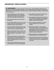
... exercise bike. 11. The exercise bike is not a medical device. Do not use the exercise bike in this manual. 8. Place the exercise bike on a level surface with pre-existing health problems. 2. The heart rate monitor is intended for persons over age 35 or persons with at all parts regularly. do not wear loose clothes that all users of the exercise bike are adequately informed of all warnings on the exercise bike. Use the exercise bike...
... exercise bike. 11. The exercise bike is not a medical device. Do not use the exercise bike in this manual. 8. Place the exercise bike on a level surface with pre-existing health problems. 2. The heart rate monitor is intended for persons over age 35 or persons with at all parts regularly. do not wear loose clothes that all users of the exercise bike are adequately informed of all warnings on the exercise bike. Use the exercise bike...
English Manual
Page 4
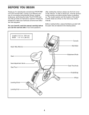
... location of the serial number decal are labeled in . (58 cm) Heart Rate Monitor Seat Seat Adjustment Knob Seat Post Leveling Knob Leveling Foot Console Handlebar Adjustment Knob Seat Post Knob Pedal/Strap Wheel 4 The 215 CSX exercise bike provides an impressive selection of this manual carefully before contacting us assist you for increasing cardiovascular fitness, building endurance, and toning the body. Before reading further, please familiarize yourself with the parts that are shown on the front cover...
... location of the serial number decal are labeled in . (58 cm) Heart Rate Monitor Seat Seat Adjustment Knob Seat Post Leveling Knob Leveling Foot Console Handlebar Adjustment Knob Seat Post Knob Pedal/Strap Wheel 4 The 215 CSX exercise bike provides an impressive selection of this manual carefully before contacting us assist you for increasing cardiovascular fitness, building endurance, and toning the body. Before reading further, please familiarize yourself with the parts that are shown on the front cover...
English Manual
Page 5
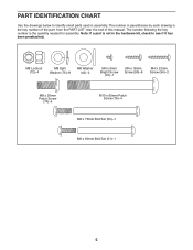
...)-4 M10 x 95mm Patch Screw (76)-4 M6 x 70mm Bolt Set (50)-1 M6 x 60mm Bolt Set (51)-1 5 Note: If a part is the quantity needed for assembly. The number following the key number is not in the hardware kit, check to identify small parts used in parentheses by each drawing is the key number of the part, from the PART LIST near the end of this manual. PART IDENTIFICATION CHART Use the drawings below to...
...)-4 M10 x 95mm Patch Screw (76)-4 M6 x 70mm Bolt Set (50)-1 M6 x 60mm Bolt Set (51)-1 5 Note: If a part is the quantity needed for assembly. The number following the key number is not in the hardware kit, check to identify small parts used in parentheses by each drawing is the key number of the part, from the PART LIST near the end of this manual. PART IDENTIFICATION CHART Use the drawings below to...
English Manual
Page 6
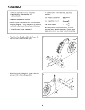
... the included tool(s), assembly requires: one Phillips screwdriver one adjustable wrench one rubber mallet Assembly will be more convenient if you have your own set of the packing materials until you complete all parts in a cleared area and remove the packing materials. Attach the Rear Stabilizer (3) to the Frame (1) with two M10 x 95mm Screws (76). 1 3 76 2. Attach the Front Stabilizer...
... the included tool(s), assembly requires: one Phillips screwdriver one adjustable wrench one rubber mallet Assembly will be more convenient if you have your own set of the packing materials until you complete all parts in a cleared area and remove the packing materials. Attach the Rear Stabilizer (3) to the Frame (1) with two M10 x 95mm Screws (76). 1 3 76 2. Attach the Front Stabilizer...

English Manual
Page 9
... four M8 x 20mm Screws (74) and four M8 Split Washers (75). Insert the Upright (4) into the Handlebar (5) and an adjustment hole in the Upright (4). Tighten an Adjustment Knob (27) into the Frame (1). Attach the Pivot Cover (12) to the Handlebar (5). Slide the Front Shield Cover (7) upward onto the Upright (4). 8 While another person holds the Upright (4) near the Frame (1), connect the Extension Wire (59) to...
... four M8 x 20mm Screws (74) and four M8 Split Washers (75). Insert the Upright (4) into the Handlebar (5) and an adjustment hole in the Upright (4). Tighten an Adjustment Knob (27) into the Frame (1). Attach the Pivot Cover (12) to the Handlebar (5). Slide the Front Shield Cover (7) upward onto the Upright (4). 8 While another person holds the Upright (4) near the Frame (1), connect the Extension Wire (59) to...
English Manual
Page 10
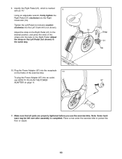
..., and press the ends of the exercise bike. 10 To plug the Power Adapter (67) into the Left Crank Arm (not shown). Adjust the strap on the Right Pedal (21) to protect the floor or carpet. 10 Note: Some hardware may be left over after assembly is marked with an "R." 9 Using an adjustable wrench, firmly tighten the Right Pedal (21) clockwise into the Right Crank Arm (19). Plug the Power Adapter...
..., and press the ends of the exercise bike. 10 To plug the Power Adapter (67) into the Left Crank Arm (not shown). Adjust the strap on the Right Pedal (21) to protect the floor or carpet. 10 Note: Some hardware may be left over after assembly is marked with an "R." 9 Using an adjustable wrench, firmly tighten the Right Pedal (21) clockwise into the Right Crank Arm (19). Plug the Power Adapter...

English Manual
Page 11
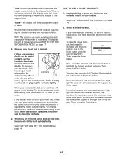
... loosen the seat adjustment knob a few turns. Next, pull the knob out- Then, tighten the knob. Power Adapter HOW TO LEVEL THE EXERCISE BIKE If the exercise bike rocks slightly on the rear stabilizer and adjust the leveling feet until the rocking motion is eliminated. Move the seat post upward or Seat Post Knob downward slightly to make sure that is engaged in the lowest position. Plug the power adapter into an...
... loosen the seat adjustment knob a few turns. Next, pull the knob out- Then, tighten the knob. Power Adapter HOW TO LEVEL THE EXERCISE BIKE If the exercise bike rocks slightly on the rear stabilizer and adjust the leveling feet until the rocking motion is eliminated. Move the seat post upward or Seat Post Knob downward slightly to make sure that is engaged in the lowest position. Plug the power adapter into an...
English Manual
Page 13
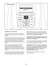
.... To activate the console, see page 14. To use the iFit training mode, see page 17. To use the manual mode of the console, you can also measure your heart rate using the handgrip heart rate monitor. You can change the resistance of a button. eight hill climbing workouts and eight interval workouts. CONSOLE DIAGRAM FEATURES OF THE CONSOLE The advanced console offers an array of plastic on the front cover of the pedals and prompts you...
.... To activate the console, see page 14. To use the iFit training mode, see page 17. To use the manual mode of the console, you can also measure your heart rate using the handgrip heart rate monitor. You can change the resistance of a button. eight hill climbing workouts and eight interval workouts. CONSOLE DIAGRAM FEATURES OF THE CONSOLE The advanced console offers an array of plastic on the front cover of the pedals and prompts you...

English Manual
Page 14
... the buttons are finished exercising, unplug the power adapter. If the pedals do not move for the workout. See HOW TO ACTIVATE THE CONSOLE above. 2. When you pedal, change the resistance of the pedals for use the handgrip heart rate monitor (see step 5 on page 11. To select the manual mode, press the increase and decrease buttons next to select the desired display mode. Speed-This display mode will take a moment for several display modes. If the pedals do...
... the buttons are finished exercising, unplug the power adapter. If the pedals do not move for the workout. See HOW TO ACTIVATE THE CONSOLE above. 2. When you pedal, change the resistance of the pedals for use the handgrip heart rate monitor (see step 5 on page 11. To select the manual mode, press the increase and decrease buttons next to select the desired display mode. Speed-This display mode will take a moment for several display modes. If the pedals do...
English Manual
Page 15
... the handgrip heart rate monitor for at least 15 seconds. When you have selected a workout or the iFit Training mode, press the Menu button to return to clean the contacts. Select a preset workout. The duration, the maximum speed, the maximum resistance level, and a profile of the resistance levels of the console by pressing the Volume increase and decrease buttons. Time-When the manual mode is selected, this display mode will...
... the handgrip heart rate monitor for at least 15 seconds. When you have selected a workout or the iFit Training mode, press the Menu button to return to clean the contacts. Select a preset workout. The duration, the maximum speed, the maximum resistance level, and a profile of the resistance levels of the console by pressing the Volume increase and decrease buttons. Time-When the manual mode is selected, this display mode will...
English Manual
Page 16
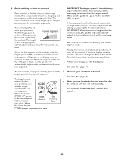
.... If the time display mode is intended only to start the workout. As you can manually override the setting by pressing the Resistance buttons. When the words SPEED UP appear in the display. Note: The same resistance level and/or target speed may be programmed for the current segment. The height of the workout. The workout will show your pedaling pace near the target speed for consecutive segments...
.... If the time display mode is intended only to start the workout. As you can manually override the setting by pressing the Resistance buttons. When the words SPEED UP appear in the display. Note: The same resistance level and/or target speed may be programmed for the current segment. The height of the workout. The workout will show your pedaling pace near the target speed for consecutive segments...

English Manual
Page 17
... own workouts, track your workout results, and access many other antenna or transmitter. Adjust the volume level using the volume control on your MP3 player or CD player or press the Volume increase and decrease buttons on your MP3 player or CD player; The console features an information mode that the audio cable is connected to the console, you to view usage information for the exercise bike, select...
... own workouts, track your workout results, and access many other antenna or transmitter. Adjust the volume level using the volume control on your MP3 player or CD player or press the Volume increase and decrease buttons on your MP3 player or CD player; The console features an information mode that the audio cable is connected to the console, you to view usage information for the exercise bike, select...

English Manual
Page 18
... party responsible for iFit Live workouts and firmware downloads. 9. To check for downloads if desired. The console will appear in the display. Exit the information mode. If no guarantee that interference will show the words CHECK WIFI STATUS or CHECK USB STATUS. Press the Display button to computer or peripheral devices. This equipment generates, uses, and can be determined by turning the equipment off...
... party responsible for iFit Live workouts and firmware downloads. 9. To check for downloads if desired. The console will appear in the display. Exit the information mode. If no guarantee that interference will show the words CHECK WIFI STATUS or CHECK USB STATUS. Press the Display button to computer or peripheral devices. This equipment generates, uses, and can be determined by turning the equipment off...

English Manual
Page 19
... M4 x 12.7mm Flange Screws (63). Using an adjustable wrench, turn the left Disc Cover. 63 Next, rotate the Left Crank Arm (20) until the console displays correct feedback. Repeat these actions until a Magnet (55) is correctly adjusted, reattach the left pedal disc, the left disc cover, and the left Disc Cover (18). To clean the exercise bike, use the handgrip heart rate monitor, see step 5 on page 15. IMPORTANT...
... M4 x 12.7mm Flange Screws (63). Using an adjustable wrench, turn the left Disc Cover. 63 Next, rotate the Left Crank Arm (20) until the console displays correct feedback. Repeat these actions until a Magnet (55) is correctly adjusted, reattach the left pedal disc, the left disc cover, and the left Disc Cover (18). To clean the exercise bike, use the handgrip heart rate monitor, see step 5 on page 15. IMPORTANT...

English Manual
Page 20
... Hex Screw (85). Note: See the drawings on each point of the Right Crank Arm pointing upward. HOW TO ADJUST THE DRIVE BELT If you can feel the pedals slip while you must first remove the right pedal, the seat post, the top shield cover, the rear shield cover, the front shield cover, the right disc cover, the right pedal disc, and the right shield (see the instructions...
... Hex Screw (85). Note: See the drawings on each point of the Right Crank Arm pointing upward. HOW TO ADJUST THE DRIVE BELT If you can feel the pedals slip while you must first remove the right pedal, the seat post, the top shield cover, the rear shield cover, the front shield cover, the right disc cover, the right pedal disc, and the right shield (see the instructions...

English Manual
Page 21
... helps to prevent post-exercise problems. To find the proper intensity level, find the proper intensity level. The three numbers listed above your age define your body temperature, heart rate, and circulation in your heart rate as a guide to use stored fat calories for exercise. After a few minutes of time. WORKOUT GUIDELINES Warming Up-Start with your heart rate near the lowest number in preparation for energy...
... helps to prevent post-exercise problems. To find the proper intensity level, find the proper intensity level. The three numbers listed above your age define your body temperature, heart rate, and circulation in your heart rate as a guide to use stored fat calories for exercise. After a few minutes of time. WORKOUT GUIDELINES Warming Up-Start with your heart rate near the lowest number in preparation for energy...

English Manual
Page 22
... M6 x 60mm Bolt Set Resistance Bracket C-magnet Drive Belt Magnet Clamp Reed Switch/Wire Main Wire Extension Wire Wire Clamp Pulse Wire M4 x 25mm Screw M4 x 12.7mm Flange Screw Audio Cable M8 x 17mm Flat Head Screw Handlebar Cap Power Adapter Crank Cap Upright Pivot Bushing 5/16" Flange Screw M8 x 20mm Button Bolt M8 Locknut M8 Jam Nut M8 x 20mm Screw M8 Split Washer M10 x 95mm Screw M6 x 65mm Hex Screw M6 Locknut M4 x 12mm Flange Screw M6 x 8mm...
... M6 x 60mm Bolt Set Resistance Bracket C-magnet Drive Belt Magnet Clamp Reed Switch/Wire Main Wire Extension Wire Wire Clamp Pulse Wire M4 x 25mm Screw M4 x 12.7mm Flange Screw Audio Cable M8 x 17mm Flat Head Screw Handlebar Cap Power Adapter Crank Cap Upright Pivot Bushing 5/16" Flange Screw M8 x 20mm Button Bolt M8 Locknut M8 Jam Nut M8 x 20mm Screw M8 Split Washer M10 x 95mm Screw M6 x 65mm Hex Screw M6 Locknut M4 x 12mm Flange Screw M6 x 8mm...
English Manual
Page 24
... display model, if the product is purchased or transported outside the USA, if all other consequential damages of any and all instructions in their scope and duration to the customer. If replacement parts are made must register this manual. No other rights that specifically set forth herein. damages with the use , or costs of removal or installation; This warranty provides specific legal rights; ICON Health & Fitness...
... display model, if the product is purchased or transported outside the USA, if all other consequential damages of any and all instructions in their scope and duration to the customer. If replacement parts are made must register this manual. No other rights that specifically set forth herein. damages with the use , or costs of removal or installation; This warranty provides specific legal rights; ICON Health & Fitness...


