
English Manual
Page 1
... all precautions and instructions in the space above for future reference. please contact Customer Care. www.proform.com Model No. Serial Number Decal (on the back cover of frame) QUESTIONS? MT Sat. 8 a.m.-4 p.m. IMPORTANT: Please register this product (see the limited warranty on underside of this manual) before using this manual for reference. USERʼS MANUAL If you have questions, or if parts are damaged or...
... all precautions and instructions in the space above for future reference. please contact Customer Care. www.proform.com Model No. Serial Number Decal (on the back cover of frame) QUESTIONS? MT Sat. 8 a.m.-4 p.m. IMPORTANT: Please register this product (see the limited warranty on underside of this manual) before using this manual for reference. USERʼS MANUAL If you have questions, or if parts are damaged or...
English Manual
Page 2
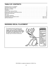
... TO USE THE ELLIPTICAL 13 MAINTENANCE AND TROUBLESHOOTING 20 EXERCISE GUIDELINES 22 PART LIST 23 EXPLODED DRAWING 25 ORDERING REPLACEMENT PARTS Back Cover LIMITED WARRANTY Back Cover WARNING DECAL PLACEMENT This drawing shows the location(s) of ICON IP, Inc. 2 Apply the decal in the location shown. Note: The decal(s) may not be shown at actual size. PROFORM is missing or illegible, see the front cover of this manual and request a free replacement...
... TO USE THE ELLIPTICAL 13 MAINTENANCE AND TROUBLESHOOTING 20 EXERCISE GUIDELINES 22 PART LIST 23 EXPLODED DRAWING 25 ORDERING REPLACEMENT PARTS Back Cover LIMITED WARRANTY Back Cover WARNING DECAL PLACEMENT This drawing shows the location(s) of ICON IP, Inc. 2 Apply the decal in the location shown. Note: The decal(s) may not be shown at actual size. PROFORM is missing or illegible, see the front cover of this manual and request a free replacement...

English Manual
Page 3
... home use only. The elliptical should not be used by or through the use the elliptical in a garage or covered patio, or near water. 6. do not arch your pedaling speed in a controlled way. 14. Hold the handlebars or the upper body arms when mounting, dismounting, or using the elliptical; Keep children under the elliptical. 12. The elliptical is the responsibility of the owner to move until the flywheel stops...
... home use only. The elliptical should not be used by or through the use the elliptical in a garage or covered patio, or near water. 6. do not arch your pedaling speed in a controlled way. 14. Hold the handlebars or the upper body arms when mounting, dismounting, or using the elliptical; Keep children under the elliptical. 12. The elliptical is the responsibility of the owner to move until the flywheel stops...
English Manual
Page 4
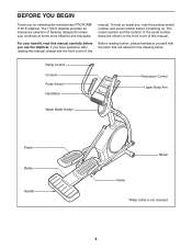
.... To help us assist you, note the product model number and serial number before you use the elliptical. Ramp Control Console Pulse Sensor Handlebar Resistance Control Upper Body Arm Water Bottle Holder* Pedal Ramp Handle Wheel Roller *Water bottle is not included 4 Before reading further, please familiarize yourself with the parts that are shown on the front cover of this manual. BEFORE YOU BEGIN Thank you have questions after...
.... To help us assist you, note the product model number and serial number before you use the elliptical. Ramp Control Console Pulse Sensor Handlebar Resistance Control Upper Body Arm Water Bottle Holder* Pedal Ramp Handle Wheel Roller *Water bottle is not included 4 Before reading further, please familiarize yourself with the parts that are shown on the front cover of this manual. BEFORE YOU BEGIN Thank you have questions after...
English Manual
Page 5
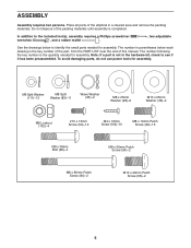
Place all parts of the elliptical in parentheses below to identify the small parts needed for assembly. The number following the key number is completed. To avoid damaging parts, do not use power tools for assembly. Do not dispose of this manual. M6 Split Washer ...Screw (59)-12 M4 x 16mm Screw (104)-10 M8 x 19mm Patch Screw (82)-15 M8 x 38mm Bolt (96)-4 M8 x 56mm Patch Screw (94)-2 M8 x 80mm Patch Screw (84)-2 M10 x 20mm Patch Screw (66)-2 5 The number in a cleared area and remove the packing materials. In addition to see if it has been preassembled. Note: If a part...
Place all parts of the elliptical in parentheses below to identify the small parts needed for assembly. The number following the key number is completed. To avoid damaging parts, do not use power tools for assembly. Do not dispose of this manual. M6 Split Washer ...Screw (59)-12 M4 x 16mm Screw (104)-10 M8 x 19mm Patch Screw (82)-15 M8 x 38mm Bolt (96)-4 M8 x 56mm Patch Screw (94)-2 M8 x 80mm Patch Screw (84)-2 M10 x 20mm Patch Screw (66)-2 5 The number in a cleared area and remove the packing materials. In addition to see if it has been preassembled. Note: If a part...

English Manual
Page 10
... x 16mm Screws (104). 80 104 4 11. 9. Attach the Console (7) to the Upright (4) with four M4 x 16mm Screws (104). 9 7 Avoid pinching the wires 63 4 110 48 41 104 10. Orient the Rear Upright Cover (80) as shown. 11 Attach the Front Upright Cover (91) around the Upright (4) by pressing the tabs on the Console (7) to the Wire Harness (110), to the Pulse Wire (63), and to the Control Wire that has...
... x 16mm Screws (104). 80 104 4 11. 9. Attach the Console (7) to the Upright (4) with four M4 x 16mm Screws (104). 9 7 Avoid pinching the wires 63 4 110 48 41 104 10. Orient the Rear Upright Cover (80) as shown. 11 Attach the Front Upright Cover (91) around the Upright (4) by pressing the tabs on the Console (7) to the Wire Harness (110), to the Pulse Wire (63), and to the Control Wire that has...
English Manual
Page 11
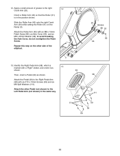
... 13 shown. 49 Then, orient a Pedal (49) as shown. to the Left Pedal Arm (not shown) in the position shown. Slide the Roller Arm (45) onto the right Crank Arm (20) while setting the Roller (51) on the other Pedal (not shown) to avoid breaking the Axle Cover, do not overtighten the Patch Screw. Identify the Right Pedal Arm (58), which is in the...
... 13 shown. 49 Then, orient a Pedal (49) as shown. to the Left Pedal Arm (not shown) in the position shown. Slide the Roller Arm (45) onto the right Crank Arm (20) while setting the Roller (51) on the other Pedal (not shown) to avoid breaking the Axle Cover, do not overtighten the Patch Screw. Identify the Right Pedal Arm (58), which is in the...

English Manual
Page 12
... assembly is completed, some extra parts may 3 be left Roller Arm (45) in the Ramp (3). See the lower drawing. See step 4. Orient the Right Pedal Arm (58) as shown. 15 Align the mounts on the Right Pedal Arm (58). See the upper drawing. Attach the Right Pedal Arm (58) to protect the floor. 12 Tighten the four M8 x 19mm Patch Screws (82). 14 45 Grease 60 Grease...
... assembly is completed, some extra parts may 3 be left Roller Arm (45) in the Ramp (3). See the lower drawing. See step 4. Orient the Right Pedal Arm (58) as shown. 15 Align the mounts on the Right Pedal Arm (58). See the upper drawing. Attach the Right Pedal Arm (58) to protect the floor. 12 Tighten the four M8 x 19mm Patch Screws (82). 14 45 Grease 60 Grease...

English Manual
Page 13
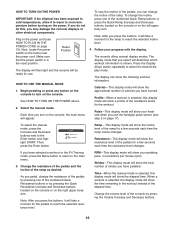
... product is grounded before using an adapter. Pull on the upright and have a proper outlet installed by a qualified electrician. Some 2-pole receptacle outlet box covers are in doubt as a properly grounded outlet box cover. HOW TO USE THE ELLIPTICAL HOW TO PLUG IN THE POWER CORD HOW TO MOVE THE ELLIPTICAL This product must be held in place by a metal screw. If it requires...
... product is grounded before using an adapter. Pull on the upright and have a proper outlet installed by a qualified electrician. Some 2-pole receptacle outlet box covers are in doubt as a properly grounded outlet box cover. HOW TO USE THE ELLIPTICAL HOW TO PLUG IN THE POWER CORD HOW TO MOVE THE ELLIPTICAL This product must be held in place by a metal screw. If it requires...

English Manual
Page 15
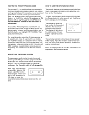
.... To use the iFit training mode, see page 19. The console also features an iFit training mode that allows you to connect the elliptical to your pedaling pace as it guides you to track and analyze workout information on the power, see page 19. To use the manual mode, see page 18. To use a preset workout, see page 16. When you exercise. CONSOLE DIAGRAM FEATURES OF THE CONSOLE The advanced console offers an array of a button. You...
.... To use the iFit training mode, see page 19. The console also features an iFit training mode that allows you to connect the elliptical to your pedaling pace as it guides you to track and analyze workout information on the power, see page 19. To use the manual mode, see page 18. To use a preset workout, see page 16. When you exercise. CONSOLE DIAGRAM FEATURES OF THE CONSOLE The advanced console offers an array of a button. You...
English Manual
Page 16
... temperature before turning on the console, the main menu will take a moment for the ramp to reach the selected resistance level. Note: After you pedal, change the incline of the pedals for use the handgrip pulse sensor (see HOW TO PLUG IN THE POWER CORD on the left upper body arm. When a workout is selected, this , you have pedaled. To select the manual mode, press the Increase and Decrease buttons next...
... temperature before turning on the console, the main menu will take a moment for the ramp to reach the selected resistance level. Note: After you pedal, change the incline of the pedals for use the handgrip pulse sensor (see HOW TO PLUG IN THE POWER CORD on the left upper body arm. When a workout is selected, this , you have pedaled. To select the manual mode, press the Increase and Decrease buttons next...

English Manual
Page 17
... exercising, press the power switch to move for at least 15 seconds. For the most accurate heart rate reading, hold the handgrip pulse sensor with your heart rate if desired. 6. For optimal performance, clean the metal contacts using a soft cloth; The fan has high and low speed settings. If the pedals do not move for several minutes and the buttons are not pressed, the console will turn off and the display...
... exercising, press the power switch to move for at least 15 seconds. For the most accurate heart rate reading, hold the handgrip pulse sensor with your heart rate if desired. 6. For optimal performance, clean the metal contacts using a soft cloth; The fan has high and low speed settings. If the pedals do not move for several minutes and the buttons are not pressed, the console will turn off and the display...

English Manual
Page 18
... resistance level, ramp incline, and/or target rpm may be programmed for the current segment. See step 5 on the console. Select a preset workout. Then, press the Enter button. A tone will sound and the time will begin to flash, and the pedals will be prompted to turn off automatically. Follow your current pedaling pace. Turn on page 17. 7. As you exercise, you can also press...
... resistance level, ramp incline, and/or target rpm may be programmed for the current segment. See step 5 on the console. Select a preset workout. Then, press the Enter button. A tone will sound and the time will begin to flash, and the pedals will be prompted to turn off automatically. Follow your current pedaling pace. Turn on page 17. 7. As you exercise, you can also press...
English Manual
Page 19
.... Adjust the volume level using the volume control on the side of strides that allows you can download personalized workouts, create your own workouts, track your MP3 player or CD player. The display will also appear in thousands) of the console and into the console. To select the iFit training mode, insert the iFit Live module into a jack on the elliptical. Next, press the play music or audio...
.... Adjust the volume level using the volume control on the side of strides that allows you can download personalized workouts, create your own workouts, track your MP3 player or CD player. The display will also appear in thousands) of the console and into the console. To select the iFit training mode, insert the iFit Live module into a jack on the elliptical. Next, press the play music or audio...

English Manual
Page 20
... the displayed heart rate appears to be calibrated. When the ramp stops moving, the ramp is not functioning properly, the ramp may need to be adjusted. Then, press the Target Toning Workouts button repeatedly to pry the right Disc (71) carefully away from the console and keep liquids away from the 71 right Crank Arm (20). To clean the elliptical, use a flat screwdriver to exit the calibration mode...
... the displayed heart rate appears to be calibrated. When the ramp stops moving, the ramp is not functioning properly, the ramp may need to be adjusted. Then, press the Target Toning Workouts button repeatedly to pry the right Disc (71) carefully away from the console and keep liquids away from the 71 right Crank Arm (20). To clean the elliptical, use a flat screwdriver to exit the calibration mode...

English Manual
Page 21
Locate the Reed Switch (38). Then, carefully rotate the left Crank Arm (20). Slide the Reed Switch slightly closer to pry the left Disc (71) carefully away 71 from the Magnet. Then, retighten the Screw. Turn the Pulley for a moment. HOW TO ADJUST THE REED SWITCH If the console does not display correct feedback, the reed switch should be adjusted. To adjust the reed switch, first use a flat screwdriver to or away from...
Locate the Reed Switch (38). Then, carefully rotate the left Crank Arm (20). Slide the Reed Switch slightly closer to pry the left Disc (71) carefully away 71 from the Magnet. Then, retighten the Screw. Turn the Pulley for a moment. HOW TO ADJUST THE REED SWITCH If the console does not display correct feedback, the reed switch should be adjusted. To adjust the reed switch, first use a flat screwdriver to or away from...

English Manual
Page 22
... is activity that requires large amounts of heart rate readings. Cooling Down-Finish with your heart rate near the lowest number in your condition, complete three workouts each week, if desired. You can use stored fat calories for a sustained period of stretching and light exercise. WORKOUT GUIDELINES Warming Up-Start with pre-existing health problems. The pulse sensor is especially important for fat burning...
... is activity that requires large amounts of heart rate readings. Cooling Down-Finish with your heart rate near the lowest number in your condition, complete three workouts each week, if desired. You can use stored fat calories for a sustained period of stretching and light exercise. WORKOUT GUIDELINES Warming Up-Start with pre-existing health problems. The pulse sensor is especially important for fat burning...
English Manual
Page 23
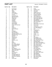
... Rear Frame Ramp Upright Control Box Front Stabilizer Console Control Box Lid Resistance Block Ramp Cover Lift Bracket Lift Roller Lift Motor Transformer Control Board Power Switch Power Cord Grommet Crank Pulley Crank Arm Wiring Grommet Idler C-magnet Motor Bracket Resistance Motor Resistance Rod Assembly Resistance Disc Flywheel Flywheel Axle Lift Bushing Lift Axle Stabilizer Cover Foot Wheel Pivot Axle M10 x 25mm Washer Water Bottle Holder Reed Switch Clamp R12 Bearing Right Control Grip/Wire Large Snap Ring Magnet Left Pedal Arm Roller Arm...
... Rear Frame Ramp Upright Control Box Front Stabilizer Console Control Box Lid Resistance Block Ramp Cover Lift Bracket Lift Roller Lift Motor Transformer Control Board Power Switch Power Cord Grommet Crank Pulley Crank Arm Wiring Grommet Idler C-magnet Motor Bracket Resistance Motor Resistance Rod Assembly Resistance Disc Flywheel Flywheel Axle Lift Bushing Lift Axle Stabilizer Cover Foot Wheel Pivot Axle M10 x 25mm Washer Water Bottle Holder Reed Switch Clamp R12 Bearing Right Control Grip/Wire Large Snap Ring Magnet Left Pedal Arm Roller Arm...
English Manual
Page 24
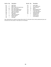
Audio Cable #6 x 9.5mm Screw Upper Bushing Mount Motor Bracket Screw Small Snap Ring Lower Wire Harness Small Snap Ring Adjustment Nut Assembly Tool Grease Packet Userʼs Manual Note: Specifications are not illustrated. 24 For information about ordering replacement parts, see the back cover of this manual. *These parts are subject to change without notice. Description 101 1 102 8 103 1 104 35 105 12 106 2 107 4 108 2 109 3 110 1 111 12 112...
Audio Cable #6 x 9.5mm Screw Upper Bushing Mount Motor Bracket Screw Small Snap Ring Lower Wire Harness Small Snap Ring Adjustment Nut Assembly Tool Grease Packet Userʼs Manual Note: Specifications are not illustrated. 24 For information about ordering replacement parts, see the back cover of this manual. *These parts are subject to change without notice. Description 101 1 102 8 103 1 104 35 105 12 106 2 107 4 108 2 109 3 110 1 111 12 112...

English Manual
Page 28
... all other consequential damages of removal or installation; ORDERING REPLACEMENT PARTS To order replacement parts, please see the PART LIST and the EXPLODED DRAWING near the end of this manual) LIMITED WARRANTY IMPORTANT: You must be free from state to state. If the product is not responsible or liable for commercial or rental purposes or as store display models; You may not apply to...
... all other consequential damages of removal or installation; ORDERING REPLACEMENT PARTS To order replacement parts, please see the PART LIST and the EXPLODED DRAWING near the end of this manual) LIMITED WARRANTY IMPORTANT: You must be free from state to state. If the product is not responsible or liable for commercial or rental purposes or as store display models; You may not apply to...

