
User Manual
Page 2
...the discharge opening at the lowest possible speed when on a slope. Avoid discharging material against a wall or obstruction. Stop the blades when crossing gravel surfaces. • Do not operate machine without the entire grass catcher, discharge chute, or other safety devices in... discharged material toward the operator. FAILURE TO OBSERVE THE FOLLOWING SAFETY INSTRUCTIONS COULD RESULT IN SERIOUS INJURY OR DEATH. Shut off blades, set parking brake, stop before storage. Always look down slopes. SLOPE OPERATION Slopes are involved in reverse unless absolutely necessary....
...the discharge opening at the lowest possible speed when on a slope. Avoid discharging material against a wall or obstruction. Stop the blades when crossing gravel surfaces. • Do not operate machine without the entire grass catcher, discharge chute, or other safety devices in... discharged material toward the operator. FAILURE TO OBSERVE THE FOLLOWING SAFETY INSTRUCTIONS COULD RESULT IN SERIOUS INJURY OR DEATH. Shut off blades, set parking brake, stop before storage. Always look down slopes. SLOPE OPERATION Slopes are involved in reverse unless absolutely necessary....
User Manual
Page 3
... appear in the mowing area for another ride and be seriously injured or interfere with manufacturer's recommended parts, when necessary. • Mower blades are sharp. Check their proper operation regularly. • Keep machine free of grass, leaves, or other sources of the towed equipment may...Remove gas-powered equipment from a gasoline dispenser nozzle. • Keep the nozzle in safe working condition. • Never tamper with the blades shut off and be sure the equipment is complete. IV. Do not attach towed equipment except at all times until fueling is in contact...
... appear in the mowing area for another ride and be seriously injured or interfere with manufacturer's recommended parts, when necessary. • Mower blades are sharp. Check their proper operation regularly. • Keep machine free of grass, leaves, or other sources of the towed equipment may...Remove gas-powered equipment from a gasoline dispenser nozzle. • Keep the nozzle in safe working condition. • Never tamper with the blades shut off and be sure the equipment is complete. IV. Do not attach towed equipment except at all times until fueling is in contact...
User Manual
Page 4
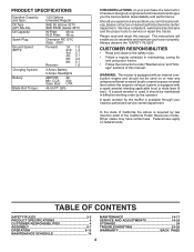
... apply on federal lands. PRODUCT SPECIFICATIONS Gasoline Capacity and Type: Oil Type (API-SG-SL): Oil Capacity: Spark Plug: Ground Speed (MPH): Charging System: Battery: Blade Bolt Torque: 1.50 Gallons Unleaded Regular SAE 30 (above is equipped with a spark arrester meeting applicable local or state laws (if any). CCA: 230 Case...
... apply on federal lands. PRODUCT SPECIFICATIONS Gasoline Capacity and Type: Oil Type (API-SG-SL): Oil Capacity: Spark Plug: Ground Speed (MPH): Charging System: Battery: Blade Bolt Torque: 1.50 Gallons Unleaded Regular SAE 30 (above is equipped with a spark arrester meeting applicable local or state laws (if any). CCA: 230 Case...

User Manual
Page 7
... them before tightening adjustment knob. • Remove adjustment knob and flat washer securing seat to cardboard packing and set aside for replacing motion and mower blade drive belts in the Service and Adjustments section of this manual. eration System (ROS) are properly inflated. (For shipping purposes, the tires were overinflated at...
... them before tightening adjustment knob. • Remove adjustment knob and flat washer securing seat to cardboard packing and set aside for replacing motion and mower blade drive belts in the Service and Adjustments section of this manual. eration System (ROS) are properly inflated. (For shipping purposes, the tires were overinflated at...

User Manual
Page 9
... for braking the tractor and starting and controlling engine speed. (E) ATTACHMENT CLUTCH LEVER - Allows operation of various controls and adjustments. Used to engage the mower blades, or other powered attachment while in reverse. (H) LIGHT SWITCH - Selects the speed and direction of the American National Standards Institute. (A) ATTACHMENT LIFT LEVER - Turns the...
... for braking the tractor and starting and controlling engine speed. (E) ATTACHMENT CLUTCH LEVER - Allows operation of various controls and adjustments. Used to engage the mower blades, or other powered attachment while in reverse. (H) LIGHT SWITCH - Selects the speed and direction of the American National Standards Institute. (A) ATTACHMENT LIFT LEVER - Turns the...

User Manual
Page 10
... release clutch/brake pedal to stop tractor completely, as described above, before stopping may cause "browning" of grass. Fig. 5 STOPPING (See Fig. 6) MOWER BLADES • To stop mower blades, move throttle control between half and full speed (fast) position. D F Fig. 7 TO MOVE FORWARD AND BACKWARD (See Fig. 8) ( ) ATTACHMENT CLUTCH LEVER "DISENGAGED" ( ) ATTACHMENT...
... release clutch/brake pedal to stop tractor completely, as described above, before stopping may cause "browning" of grass. Fig. 5 STOPPING (See Fig. 6) MOWER BLADES • To stop mower blades, move throttle control between half and full speed (fast) position. D F Fig. 7 TO MOVE FORWARD AND BACKWARD (See Fig. 8) ( ) ATTACHMENT CLUTCH LEVER "DISENGAGED" ( ) ATTACHMENT...
User Manual
Page 11
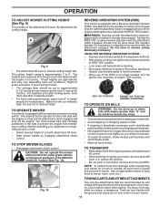
... to tractor. OPERATION TO ADJUST MOWER CUTTING HEIGHT (See Fig. 9) The position of cut with attachment lift lever. • Start mower blades by the operator to travel in the reverse direction with the attachment clutch engaged will shut off the engine unless ignition key is dangerous. A...seat to prevent the engine from damage when transporting your equipment on a slope, is placed in place (See Fig. 10). TO STOP MOWER BLADES • Disengage attachment clutch control. TO TRANSPORT • Raise attachment lift to desired height. NOTE: To protect hood from hesitating or cutting ...
... to tractor. OPERATION TO ADJUST MOWER CUTTING HEIGHT (See Fig. 9) The position of cut with attachment lift lever. • Start mower blades by the operator to travel in the reverse direction with the attachment clutch engaged will shut off the engine unless ignition key is dangerous. A...seat to prevent the engine from damage when transporting your equipment on a slope, is placed in place (See Fig. 10). TO STOP MOWER BLADES • Disengage attachment clutch control. TO TRANSPORT • Raise attachment lift to desired height. NOTE: To protect hood from hesitating or cutting ...
User Manual
Page 14
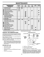
...; Check tire pressure. • Check operator presence and ROS systems for proper operation. • Check for Loose Fasteners C Check/Replace Mower Blades 3 T Lubrication Chart 0 Check Battery Level 4 R Clean Battery and Terminals Clean Debris Off Steering Plate 5 Check Transaxle Cooling Check Mower Levelness... and last longer. VISCOUS LUBRICANTS WILL ATTRACT DUST AND DIRT THAT WILL SHORTEN THE LIFE OF THE SELF-LUBRICATING BEARINGS. Replace blades more often when operating under a heavy load or in Maintenance Section. Not required if equipped with oil filter) Change Engine ...
...; Check tire pressure. • Check operator presence and ROS systems for proper operation. • Check for Loose Fasteners C Check/Replace Mower Blades 3 T Lubrication Chart 0 Check Battery Level 4 R Clean Battery and Terminals Clean Debris Off Steering Plate 5 Check Transaxle Cooling Check Mower Levelness... and last longer. VISCOUS LUBRICANTS WILL ATTRACT DUST AND DIRT THAT WILL SHORTEN THE LIFE OF THE SELF-LUBRICATING BEARINGS. Replace blades more often when operating under a heavy load or in Maintenance Section. Not required if equipped with oil filter) Change Engine ...
User Manual
Page 15
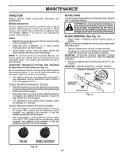
... should shut off the engine. • When the engine is engaged, any attempt by turning counterclockwise. • Install new or resharpened blade with the ignition switch in the seat. MAINTENANCE TRACTOR Always observe safety rules when performing any attempt by the operator to slow leaks, tire... unless the operator is in all tires (See the sides of tires for proper PSI). • Keep tires free of this manual). MANDREL ASSEMBLY BLADE BLADE BOLT (SPECIAL) CENTER HOLE Fig. 13 STAR ROS "ON" POSITION 02828 ENGINE "ON" POSITION (NORMAL OPERATING) Fig. 12 15 NOTE: Protect your...
... should shut off the engine. • When the engine is engaged, any attempt by turning counterclockwise. • Install new or resharpened blade with the ignition switch in the seat. MAINTENANCE TRACTOR Always observe safety rules when performing any attempt by the operator to slow leaks, tire... unless the operator is in all tires (See the sides of tires for proper PSI). • Keep tires free of this manual). MANDREL ASSEMBLY BLADE BLADE BOLT (SPECIAL) CENTER HOLE Fig. 13 STAR ROS "ON" POSITION 02828 ENGINE "ON" POSITION (NORMAL OPERATING) Fig. 12 15 NOTE: Protect your...
User Manual
Page 18
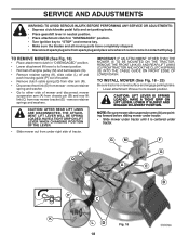
... gearshift lever in neutral position. • Place attachment clutch in "DISENGAGED" position. • Turn ignition key to "STOP" and remove key. • Make sure the blades and all moving parts have completely stopped. • Disconnect spark plug wire from rear mower bracket (D) - HAVE A TIGHT GRIP ON LIFT LEVER, LOWER IT SLOWLY...
... gearshift lever in neutral position. • Place attachment clutch in "DISENGAGED" position. • Turn ignition key to "STOP" and remove key. • Make sure the blades and all moving parts have completely stopped. • Disconnect spark plug wire from rear mower bracket (D) - HAVE A TIGHT GRIP ON LIFT LEVER, LOWER IT SLOWLY...
User Manual
Page 20
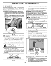
... the rear tip. • Hold adjustment nut in its highest position. • At both sides. Protect your hands with gloves and/or wrap blade with wrench and tighten jam nut securely against adjustment nut. 20 TIGHTEN ADJUST NUT B TO RAISE MOWER 02950 LOOSEN JAM NUT A FIRST LOOSEN ADJUST... uncut grass and visually checking the appearance. B A • Raise mower to raise LH side of the blade. If tires are sharp. To obtain the best cutting results, the mower blades should be adjusted so the front tip is pointing straight forward. B B Turn nut right to raise mower ...
... the rear tip. • Hold adjustment nut in its highest position. • At both sides. Protect your hands with gloves and/or wrap blade with wrench and tighten jam nut securely against adjustment nut. 20 TIGHTEN ADJUST NUT B TO RAISE MOWER 02950 LOOSEN JAM NUT A FIRST LOOSEN ADJUST... uncut grass and visually checking the appearance. B A • Raise mower to raise LH side of the blade. If tires are sharp. To obtain the best cutting results, the mower blades should be adjusted so the front tip is pointing straight forward. B B Turn nut right to raise mower ...
User Manual
Page 21
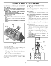
...manual). The rear wheels must be serviced. A B D E F G 02954 Manual Fig. 29 21 SERVICE AND ADJUSTMENTS TO REPLACE MOWER BLADE DRIVE BELT (See Fig. 28) The mower blade drive belt may also check brake by: • Park tractor on a level, dry concrete or paved surface, then brake must lock ...and skid when you try to front, over cooling fan blades (D). • Remove belt downward from tractor (See "TO REMOVE MOWER" in highest gear on a level, dry concrete or paved surface, depress brake pedal...
...manual). The rear wheels must be serviced. A B D E F G 02954 Manual Fig. 29 21 SERVICE AND ADJUSTMENTS TO REPLACE MOWER BLADE DRIVE BELT (See Fig. 28) The mower blade drive belt may also check brake by: • Park tractor on a level, dry concrete or paved surface, then brake must lock ...and skid when you try to front, over cooling fan blades (D). • Remove belt downward from tractor (See "TO REMOVE MOWER" in highest gear on a level, dry concrete or paved surface, depress brake pedal...
User Manual
Page 26
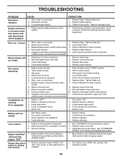
..." while mower or other attachment is shifted into reverse 1. Install axle key at rear wheel. TROUBLESHOOTING PROBLEM Excessive vibration CAUSE 1. Bent blade mandrel. 3. CORRECTION 1. Mower deck not level. 4. Low/uneven tire air pressure. 5. Replace mower drive belt. 9. Replace with...fast) position before stopping engine. 1. See "TO REMOVE WHEEL" in the maintenance section. 2. Worn, bent or loose blade. 2. Replace blade mandrel. Replace blade. Buildup of mower housing. 4. Mower drive belt worn. 8. of drive Engine "backfires" when turning engine "OFF" ...
..." while mower or other attachment is shifted into reverse 1. Install axle key at rear wheel. TROUBLESHOOTING PROBLEM Excessive vibration CAUSE 1. Bent blade mandrel. 3. CORRECTION 1. Mower deck not level. 4. Low/uneven tire air pressure. 5. Replace mower drive belt. 9. Replace with...fast) position before stopping engine. 1. See "TO REMOVE WHEEL" in the maintenance section. 2. Worn, bent or loose blade. 2. Replace blade mandrel. Replace blade. Buildup of mower housing. 4. Mower drive belt worn. 8. of drive Engine "backfires" when turning engine "OFF" ...
User Manual
Page 28
... replace, without charge for the movement of any product which have other rights which we find to any power equipment unit or attachment are belts, blades, blade adapters, normal wear, normal adjustments, standard hardware and normal maintenance. 7. Battery must return the product to an authorized service dealer.
... replace, without charge for the movement of any product which have other rights which we find to any power equipment unit or attachment are belts, blades, blade adapters, normal wear, normal adjustments, standard hardware and normal maintenance. 7. Battery must return the product to an authorized service dealer.
Parts Manual
Page 15
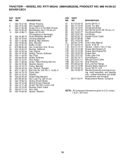
PXT195G42 (96046002200), PRODUCT NO. 960 46 00-22 MOWER DECK KEY PART NO. NO. DESCRIPTION 1 532 19 47-92 Mower Housing 6 532 19 51-86 Arm Suspension 7 532 41 63-58 Screw #10 x 0.750 BOS Thread 8 532 19 30-03 Bolt/Washer Asm 7/16-20 unf 11 532 13 89-71 Blade... Stud Fastener Nut Lock Hex Flange Bracket Brake Stand LH Screw 3/8-16 x 3/4 Mandrel Assembly (Includes housing, shaft assembly, and bearing only - pulley/nut/washer and blade bolt/washers not included) Replacement Mower, Complete NOTE: All component dimensions given in U.S. TRACTOR - - inches 1 inch = 25.4 mm 15 MODEL NO. NO....
PXT195G42 (96046002200), PRODUCT NO. 960 46 00-22 MOWER DECK KEY PART NO. NO. DESCRIPTION 1 532 19 47-92 Mower Housing 6 532 19 51-86 Arm Suspension 7 532 41 63-58 Screw #10 x 0.750 BOS Thread 8 532 19 30-03 Bolt/Washer Asm 7/16-20 unf 11 532 13 89-71 Blade... Stud Fastener Nut Lock Hex Flange Bracket Brake Stand LH Screw 3/8-16 x 3/4 Mandrel Assembly (Includes housing, shaft assembly, and bearing only - pulley/nut/washer and blade bolt/washers not included) Replacement Mower, Complete NOTE: All component dimensions given in U.S. TRACTOR - - inches 1 inch = 25.4 mm 15 MODEL NO. NO....
Parts Manual
Page 20
... as noted below) or components parts thereof. Transportation charges for the movement of any parts submitted for any power equipment unit or attachment are belts, blades, blade adapters, normal wear, normal adjustments, standard hardware and normal maintenance. 7. Transportation charges for replacement under this Warranty are the responsibility of the authorized dealer from...
... as noted below) or components parts thereof. Transportation charges for the movement of any parts submitted for any power equipment unit or attachment are belts, blades, blade adapters, normal wear, normal adjustments, standard hardware and normal maintenance. 7. Transportation charges for replacement under this Warranty are the responsibility of the authorized dealer from...


