Owner's Manual
Page 5
...MENU 40 Setting the Subtitle (SUBTITLE LANG 41 - MODE Switch Setting - Searching for a Desired Scene, Starting Playback from a Specified Time - Installing the DVD Player Unit Installing the Remote Sensor 75 Appendix 77 Index 77 Specifications 78 2 Setting the Code Number and Level - Switching Power ON ITS Playback 54 Troubleshooting ...Information Display 2 of a CD 37 - Connection Diagram Transportation of a Video CD 33 - Switching Discs - Operating with the Information Display 1 of Multi-DVD Player ........ 71 Installation 72 - Connecting the Power Cord -
...MENU 40 Setting the Subtitle (SUBTITLE LANG 41 - MODE Switch Setting - Searching for a Desired Scene, Starting Playback from a Specified Time - Installing the DVD Player Unit Installing the Remote Sensor 75 Appendix 77 Index 77 Specifications 78 2 Setting the Code Number and Level - Switching Power ON ITS Playback 54 Troubleshooting ...Information Display 2 of a CD 37 - Connection Diagram Transportation of a Video CD 33 - Switching Discs - Operating with the Information Display 1 of Multi-DVD Player ........ 71 Installation 72 - Connecting the Power Cord -
Owner's Manual
Page 7
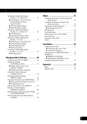
Where such regulations apply, they must be illegal. Example: When you attempt to watch a DVD (the screen is black.) When you from watching a DVD or Video CD on the display connected to watch the DVD or Video CD while Driving. 4 This product detects whether your car's parking brake is engaged or...Rear video output is visible to the driver. • In some countries or states the viewing of a display to watch the DVD or Video CD. WARNING • NEVER install the display in a location that is for use with a video screen that enables the Driver to enable passengers in a safe ...
Where such regulations apply, they must be illegal. Example: When you attempt to watch a DVD (the screen is black.) When you from watching a DVD or Video CD on the display connected to watch the DVD or Video CD while Driving. 4 This product detects whether your car's parking brake is engaged or...Rear video output is visible to the driver. • In some countries or states the viewing of a display to watch the DVD or Video CD. WARNING • NEVER install the display in a location that is for use with a video screen that enables the Driver to enable passengers in a safe ...
Owner's Manual
Page 11
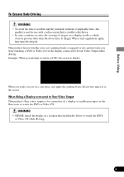
... metallic tools. • Do not store the lithium battery with metallic materials. • When disposing of battery leakage, wipe the remote controller completely clean and install a new bat- Battery • Slide the tray out on the back of children.
... metallic tools. • Do not store the lithium battery with metallic materials. • When disposing of battery leakage, wipe the remote controller completely clean and install a new bat- Battery • Slide the tray out on the back of children.
Owner's Manual
Page 66
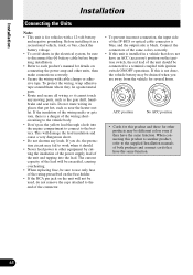
... not be used, do , the protection circuit may fail to work when it should be connected to each product's manual for several hours. Before installing it in a recreational vehicle, truck, or bus, check the battery voltage. • To avoid shorts in a vehicle that get hot, such ...lead insulation and cause a very dangerous short. • Do not shorten any moving parts, such as near the heater outlet. N STAR N STAR Installation Installation Connecting the Units Note: • This unit is for other products may be different colors even if they lie against metal parts. • Route...
... not be used, do , the protection circuit may fail to work when it should be connected to each product's manual for several hours. Before installing it in a recreational vehicle, truck, or bus, check the battery voltage. • To avoid shorts in a vehicle that get hot, such ...lead insulation and cause a very dangerous short. • Do not shorten any moving parts, such as near the heater outlet. N STAR N STAR Installation Installation Connecting the Units Note: • This unit is for other products may be different colors even if they lie against metal parts. • Route...
Owner's Manual
Page 67
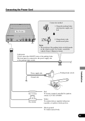
... or dealer. Clamp firmly with power regardless of the parking brake switch depends on the vehicle model. Power supply side Ground side Parking brake switch Installation Fuse resistor Fuse holder Red To electric terminal controlled by ignition switch (12 V DC) ON/OFF. Yellow To terminal always supplied with needle-nosed pliers...
... or dealer. Clamp firmly with power regardless of the parking brake switch depends on the vehicle model. Power supply side Ground side Parking brake switch Installation Fuse resistor Fuse holder Red To electric terminal controlled by ignition switch (12 V DC) ON/OFF. Yellow To terminal always supplied with needle-nosed pliers...
Owner's Manual
Page 68
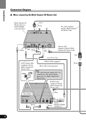
... with the Multi-Channel AV Master Unit) Green Blue This Product Black 15 cm (5/8 in .) Gray DVD control cable (supplied with the MultiChannel AV Master Unit) 6 m (19 ft. 8 in .) Yellow Black (FRONT VIDEO OUTPUT) 65 Installation Connection Diagram 7 When connecting the Multi-Channel AV Master Unit Multi-Channel AV Master Unit (e.g. AVM...
... with the Multi-Channel AV Master Unit) Green Blue This Product Black 15 cm (5/8 in .) Gray DVD control cable (supplied with the MultiChannel AV Master Unit) 6 m (19 ft. 8 in .) Yellow Black (FRONT VIDEO OUTPUT) 65 Installation Connection Diagram 7 When connecting the Multi-Channel AV Master Unit Multi-Channel AV Master Unit (e.g. AVM...

Owner's Manual
Page 69
Red Installation IP-BUS cable (supplied with the display) 66 GEX-P7000TV) (sold separately) RCA cable (sold separately) 20 pin cable Red (supplied with the TV tuner) Green 20 pin cable (supplied with the TV tuner) Multi-CD player (sold separately) Not used. Voice guidance speaker (supplied with the display) AV system display (e.g. AVX-7300) (sold separately) Blue Black Blue Hide-away TV Tuner (e.g.
Red Installation IP-BUS cable (supplied with the display) 66 GEX-P7000TV) (sold separately) RCA cable (sold separately) 20 pin cable Red (supplied with the TV tuner) Green 20 pin cable (supplied with the TV tuner) Multi-CD player (sold separately) Not used. Voice guidance speaker (supplied with the display) AV system display (e.g. AVX-7300) (sold separately) Blue Black Blue Hide-away TV Tuner (e.g.

Owner's Manual
Page 70
Installation 7 When connecting the Head Unit AV receiver/CD player with the TV tuner) Black Blue Hide-away TV Tuner (e.g. AVH-P6400CD) (sold separately) Blue Black AV-BUS cable (sold separately) Blue Blue Black AV-BUS cable (supplied with the TV tuner) Black 67 GEX-P6400TV) (sold separately) IP-BUS cable (supplied with display (e.g.
Installation 7 When connecting the Head Unit AV receiver/CD player with the TV tuner) Black Blue Hide-away TV Tuner (e.g. AVH-P6400CD) (sold separately) Blue Black AV-BUS cable (sold separately) Blue Blue Black AV-BUS cable (supplied with the TV tuner) Black 67 GEX-P6400TV) (sold separately) IP-BUS cable (supplied with display (e.g.
Owner's Manual
Page 71
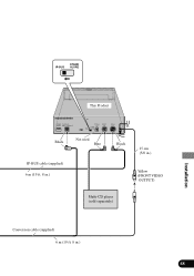
Blue IP-BUS cable (supplied) 6 m (19 ft. 8 in.) Black 15 cm (5/8 in.) Yellow (FRONT VIDEO OUTPUT) Multi-CD player (sold separately) Conversion cable (supplied) 6 m (19 ft. 8 in.) 68 This Product Installation Black Not used.
Blue IP-BUS cable (supplied) 6 m (19 ft. 8 in.) Black 15 cm (5/8 in.) Yellow (FRONT VIDEO OUTPUT) Multi-CD player (sold separately) Conversion cable (supplied) 6 m (19 ft. 8 in.) 68 This Product Installation Black Not used.
Owner's Manual
Page 72
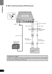
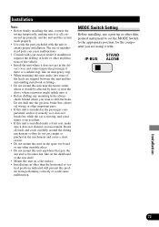
Installation 7 When connecting the display with RCA input jacks IP-BUS STAND ALONE This Product Black Audio outputs Left (White) 15 cm (5/8 in.) Right (Red) Video ...
Installation 7 When connecting the display with RCA input jacks IP-BUS STAND ALONE This Product Black Audio outputs Left (White) 15 cm (5/8 in.) Right (Red) Video ...

Owner's Manual
Page 73
This Product Audio outputs Left (White) 15 cm (5/8 in.) Right (Red) Video output Yellow (REAR VIDEO OUTPUT) RCA cable (sold separately) To audio inputs RCA cable (sold separately) To video input Display with RCA input jacks Installation 70 WARNING • NEVER install the display in a location that enables the Driver to watch the DVD or Video CD while Driving. 7 When Using a Display connected Rear Video Output This product's Rear video output is for connection of a display to enable passengers in the Rear seats to watch the DVD or Video CD.
This Product Audio outputs Left (White) 15 cm (5/8 in.) Right (Red) Video output Yellow (REAR VIDEO OUTPUT) RCA cable (sold separately) To audio inputs RCA cable (sold separately) To video input Display with RCA input jacks Installation 70 WARNING • NEVER install the display in a location that enables the Driver to watch the DVD or Video CD while Driving. 7 When Using a Display connected Rear Video Output This product's Rear video output is for connection of a display to enable passengers in the Rear seats to watch the DVD or Video CD.

Owner's Manual
Page 74
The removed transport screw should be retained in order to protect it during transportation. Seal After removing the transport screw, cover the hole with the supplied seal. After removing the transport screw, cover the hole with the supplied seal. Transport screw Attach to the original position before mounting the set . 71 Be sure to remove the transport screw before transporting the set . Installation Transportation of Multi-DVD Player A transport screw has been attached to the set in the accessory bag for use the next time the set is transported.
The removed transport screw should be retained in order to protect it during transportation. Seal After removing the transport screw, cover the hole with the supplied seal. After removing the transport screw, cover the hole with the supplied seal. Transport screw Attach to the original position before mounting the set . 71 Be sure to remove the transport screw before transporting the set . Installation Transportation of Multi-DVD Player A transport screw has been attached to the set in the accessory bag for use the next time the set is transported.
Owner's Manual
Page 75
... only the parts included with . Do not drill into the gas line, brake line, electrical wiring or other important parts. • If this unit is installed in the passenger compartment, anchor it securely so it does not break free while the car is moving, and cause injury or an accident. •... anywhere that gets the sun and so becomes hot, like on the dashboard or the rear shelf. • Mount this unit on a flat surface. • Installations in other than the horizontal or vertical positions indicated will prevent this unit near the heater outlet, where it would be affected by heat, or...
... only the parts included with . Do not drill into the gas line, brake line, electrical wiring or other important parts. • If this unit is installed in the passenger compartment, anchor it securely so it does not break free while the car is moving, and cause injury or an accident. •... anywhere that gets the sun and so becomes hot, like on the dashboard or the rear shelf. • Mount this unit on a flat surface. • Installations in other than the horizontal or vertical positions indicated will prevent this unit near the heater outlet, where it would be affected by heat, or...

Owner's Manual
Page 76
Tapping screw (6 × 16 mm) Screw (4 × 8 mm) 7 Mounting Vertically Mounting board Bracket Drill 4 to 4.5 mm diameter holes. 73 Use the holes indicated with arrows. Tapping screw (6 × 16 mm) Screw (4 × 8 mm) Mounting board Bracket Drill 4 to 4.5 mm diameter holes. Installation Installing the DVD Player Unit 7 Mounting Horizontally Use the holes indicated with arrows.
Tapping screw (6 × 16 mm) Screw (4 × 8 mm) 7 Mounting Vertically Mounting board Bracket Drill 4 to 4.5 mm diameter holes. 73 Use the holes indicated with arrows. Tapping screw (6 × 16 mm) Screw (4 × 8 mm) Mounting board Bracket Drill 4 to 4.5 mm diameter holes. Installation Installing the DVD Player Unit 7 Mounting Horizontally Use the holes indicated with arrows.

Owner's Manual
Page 77
When the mounting angle is horizontal to the ground surface, set the dial to "H" position. The angle switching dial must be installed in this direction. Top The player cannot be set the dial to the same position. Angle switching dial 2 steps 7 Angle Switching Dial Adjustment When the mounting angle is vertical to the ground surface, set on both sides of the player to "V" position. Installation 74 7 Mounting Angle Only 0 or 90 degree installation is available.
When the mounting angle is horizontal to the ground surface, set the dial to "H" position. The angle switching dial must be installed in this direction. Top The player cannot be set the dial to the same position. Angle switching dial 2 steps 7 Angle Switching Dial Adjustment When the mounting angle is vertical to the ground surface, set on both sides of the player to "V" position. Installation 74 7 Mounting Angle Only 0 or 90 degree installation is available.
Owner's Manual
Page 78
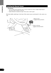
tures may be subjected to direct sunlight. Stick the double-sided tape to the back of the remote sensor, and attach it may result in damage to the center console. High tempera- Remote sensor (supplied with the CD-R7) Double-sided tape (supplied with the CD-R7) 75 Installation Installing the Remote Sensor Precaution: • Do not install on the dashboard where it to the unit. • Install within the transmission range of the remote control signal.
tures may be subjected to direct sunlight. Stick the double-sided tape to the back of the remote sensor, and attach it may result in damage to the center console. High tempera- Remote sensor (supplied with the CD-R7) Double-sided tape (supplied with the CD-R7) 75 Installation Installing the Remote Sensor Precaution: • Do not install on the dashboard where it to the unit. • Install within the transmission range of the remote control signal.


