
Owner's Manual
Page 1
Operating Instructions AUDIO/VIDEO MULTI-CHANNEL RECEIVER VSX-80TXV VSX-80TXV-S Register your product at www.pioneerelectronics.com (US) www.pioneerelectronics.ca (Canada) • Protect your new investment The details of your ...purchase will be on file for reference in the event of an insurance claim such as loss or theft. • Receive free tips, updates and service bulletins on your new product • Improve product development Your input helps us continue to design products that meet your...
Operating Instructions AUDIO/VIDEO MULTI-CHANNEL RECEIVER VSX-80TXV VSX-80TXV-S Register your product at www.pioneerelectronics.com (US) www.pioneerelectronics.ca (Canada) • Protect your new investment The details of your ...purchase will be on file for reference in the event of an insurance claim such as loss or theft. • Receive free tips, updates and service bulletins on your new product • Improve product development Your input helps us continue to design products that meet your...

Owner's Manual
Page 2
...D8-10-3a_En WARNING: Handling the cord on this equipment does cause harmful interference to radio or television reception, which the receiver is connected. - D1-4-2-1_En FEDERAL COMMUNICATIONS DECLARATION OF CONFORMITY This device complies with the instructions, may cause undesired operation. D1..., DO NOT USE THIS (POLARIZED) PLUG WITH AN EXTENSION CORD. Product Name: AUDIO/VIDEO MULTI-CHANNEL RECEIVER Model Number: VSX-80TXV, VSX-80TXV-S Responsible Party Name: PIONEER ELECTRONICS SERVICE INC. LONG BEACH, CA 90801-1760, USA Phone: 310-952-2915 IMPORTANT NOTICE - THIS...
...D8-10-3a_En WARNING: Handling the cord on this equipment does cause harmful interference to radio or television reception, which the receiver is connected. - D1-4-2-1_En FEDERAL COMMUNICATIONS DECLARATION OF CONFORMITY This device complies with the instructions, may cause undesired operation. D1..., DO NOT USE THIS (POLARIZED) PLUG WITH AN EXTENSION CORD. Product Name: AUDIO/VIDEO MULTI-CHANNEL RECEIVER Model Number: VSX-80TXV, VSX-80TXV-S Responsible Party Name: PIONEER ELECTRONICS SERVICE INC. LONG BEACH, CA 90801-1760, USA Phone: 310-952-2915 IMPORTANT NOTICE - THIS...

Owner's Manual
Page 4
...read through these operating instructions so you for future reference. After you start Features 6 Checking what's in the box 6 Ventilation 7 Installing the receiver 7 Loading the batteries 7 02 5 minute guide Introduction to home theater 8 Listening to Surround Sound 8 Automatically setting up for surround sound ... modes 27 Using the Advanced surround effects 27 Setting the effect options 27 Listening in a safe place for buying this Pioneer product. Contents 01 Before you have finished reading the instructions, put them away in stereo 28 Listening with Acoustic Calibration...
...read through these operating instructions so you for future reference. After you start Features 6 Checking what's in the box 6 Ventilation 7 Installing the receiver 7 Loading the batteries 7 02 5 minute guide Introduction to home theater 8 Listening to Surround Sound 8 Automatically setting up for surround sound ... modes 27 Using the Advanced surround effects 27 Setting the effect options 27 Listening in a safe place for buying this Pioneer product. Contents 01 Before you have finished reading the instructions, put them away in stereo 28 Listening with Acoustic Calibration...

Owner's Manual
Page 5
...multi-room connections 46 Using the multi-room controls 46 Connecting an IR receiver 47 Switching components on and off using the 12 volt trigger 48 Using this receiver with a Pioneer plasma display 48 Using the SR+ mode with a Pioneer plasma display 49 09 Other Settings The Input Assign menu 50 The ...Setup menu 51 Dynamic Range Control Setup 51 Dual Mono Setup 52 LFE Attenuator Setup 52 SR+ Setup for Pioneer plasma displays 52 Video Converter Setup 52 Multi-Room and IR receiver setup 53 12 Volt Trigger setup 53 10 Using other functions Making an audio or a video recording 54 ...
...multi-room connections 46 Using the multi-room controls 46 Connecting an IR receiver 47 Switching components on and off using the 12 volt trigger 48 Using this receiver with a Pioneer plasma display 48 Using the SR+ mode with a Pioneer plasma display 49 09 Other Settings The Input Assign menu 50 The ...Setup menu 51 Dynamic Range Control Setup 51 Dual Mono Setup 52 LFE Attenuator Setup 52 SR+ Setup for Pioneer plasma displays 52 Video Converter Setup 52 Multi-Room and IR receiver setup 53 12 Volt Trigger setup 53 10 Using other functions Making an audio or a video recording 54 ...

Owner's Manual
Page 6
...and DTS-ES decoders for six-channel surround sound. • Phase correction Based on Pioneer's unique Phase Control Technology, the Basic Phase Control feature incorporated into this receiver's design provides coherent sound reproduction through the use LCD remote control The remote control gives... series of quality and performance tests covering every aspect of a surround back speaker, you can program the remote to Pioneer for complete surround sound control you 've received the following supplied accessories: • Setup microphone (cable: 16.4 ft.) • Remote control unit • ...
...and DTS-ES decoders for six-channel surround sound. • Phase correction Based on Pioneer's unique Phase Control Technology, the Basic Phase Control feature incorporated into this receiver's design provides coherent sound reproduction through the use LCD remote control The remote control gives... series of quality and performance tests covering every aspect of a surround back speaker, you can program the remote to Pioneer for complete surround sound control you 've received the following supplied accessories: • Setup microphone (cable: 16.4 ft.) • Remote control unit • ...

Owner's Manual
Page 7
...use of the batteries properly according to the marks in direct sunlight or other excessively hot place, such as a kitchen) 7 En Installing the receiver • When installing this unit, make sure to leave space around the unit for ventilation and to protect the equipment from overheating. in your... Before you start 01 Ventilation When installing this unit, make sure to put it on a level and stable surface. Loading the batteries 8 inches Receiver (20 cm) Slot and openings in places that gives off a magnetic field). This can also reduce the life or performance of the unit, ...
...use of the batteries properly according to the marks in direct sunlight or other excessively hot place, such as a kitchen) 7 En Installing the receiver • When installing this unit, make sure to leave space around the unit for ventilation and to protect the equipment from overheating. in your... Before you start 01 Ventilation When installing this unit, make sure to put it on a level and stable surface. Loading the batteries 8 inches Receiver (20 cm) Slot and openings in places that gives off a magnetic field). This can also reduce the life or performance of the unit, ...
Owner's Manual
Page 8
... ambient noise, speaker size and distance, and tests for more on this. See Automatically setting up the microphone provided with your system, the receiver uses the information from a series of test tones to optimize the speaker settings and equalization for more on the source and the sound settings ... shown in the middle of the action or concert. See Listening to your system on page 26 for the best surround sound effect. This receiver will have to make changes for optimal surround sound. Make sure you 're in Installing your speaker system on , followed by your DVD player...
... ambient noise, speaker size and distance, and tests for more on this. See Automatically setting up the microphone provided with your system, the receiver uses the information from a series of test tones to optimize the speaker settings and equalization for more on the source and the sound settings ... shown in the middle of the action or concert. See Listening to your system on page 26 for the best surround sound effect. This receiver will have to make changes for optimal surround sound. Make sure you 're in Installing your speaker system on , followed by your DVD player...

Owner's Manual
Page 9
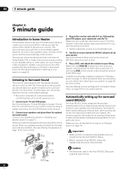
... JOG S -VIDEO VIDEO/GAME INPUT VIDEO L AUDIO R DIGITAL IN MCACC SETUP MIC 3 Press RECEIVER on the remote, then press SETUP. 5 minute guide 02 RECEIVER INPUT SELECT SYSTEM OFF SOURCE AV PRE-PROGRAMMED AND LEARNING REMOTE CONTROL UNIT DVD CD TV CD-R DVR 2 DVR1 TV CTRL XM RADIO... ROOM 2 TUNER RECEIVER DIALOG E PHASE S.RETRIEVER D.ACCESS +10 CLASS DISC ENTER TOP MENU TUNE ...
... JOG S -VIDEO VIDEO/GAME INPUT VIDEO L AUDIO R DIGITAL IN MCACC SETUP MIC 3 Press RECEIVER on the remote, then press SETUP. 5 minute guide 02 RECEIVER INPUT SELECT SYSTEM OFF SOURCE AV PRE-PROGRAMMED AND LEARNING REMOTE CONTROL UNIT DVD CD TV CD-R DVR 2 DVR1 TV CTRL XM RADIO... ROOM 2 TUNER RECEIVER DIALOG E PHASE S.RETRIEVER D.ACCESS +10 CLASS DISC ENTER TOP MENU TUNE ...
Owner's Manual
Page 10
...theater system. If a crest of a wave meets a trough (as a DVD disc) with the operation of listening to adjust the volume level. RECEIVER INPUT SELECT SYSTEM OFF SOURCE AV PRE-PROGRAMMED AND LEARNING REMOTE CONTROL UNIT GUIDE TV CONTROL TV VOL INPUT SELECT TV CH VOL DTV ON/OFF MPX REC DTVINFO... MUTE REC STOP JUKEBOX DVD CD TV CD-R DVR 2 DVR1 TV CTRL XM RADIO ROOM 2 TUNER RECEIVER AUDIO SUBTITLE HDD DISP CH...
...theater system. If a crest of a wave meets a trough (as a DVD disc) with the operation of listening to adjust the volume level. RECEIVER INPUT SELECT SYSTEM OFF SOURCE AV PRE-PROGRAMMED AND LEARNING REMOTE CONTROL UNIT GUIDE TV CONTROL TV VOL INPUT SELECT TV CH VOL DTV ON/OFF MPX REC DTVINFO... MUTE REC STOP JUKEBOX DVD CD TV CD-R DVR 2 DVR1 TV CTRL XM RADIO ROOM 2 TUNER RECEIVER AUDIO SUBTITLE HDD DISP CH...

Owner's Manual
Page 11
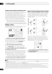
... set of components you can control all your equipment from the power outlet. Connecting your equipment 03 Chapter 3 Connecting your equipment This receiver provides you with this unit's sensor on page 61. 6 Stereo analog audio source inputs/(outputs) (x3) Use for connection to ... etc. This page explains the kinds of inputs has jacks for digital audio sources, including DVD players/recorders, digital satellite receivers, CD players, etc. Operating other Pioneer components with many connection possibilities, but it doesn't have to a monitor or TV. Rear panel CENTER L 17 OUTLET...
... set of components you can control all your equipment from the power outlet. Connecting your equipment 03 Chapter 3 Connecting your equipment This receiver provides you with this unit's sensor on page 61. 6 Stereo analog audio source inputs/(outputs) (x3) Use for connection to ... etc. This page explains the kinds of inputs has jacks for digital audio sources, including DVD players/recorders, digital satellite receivers, CD players, etc. Operating other Pioneer components with many connection possibilities, but it doesn't have to a monitor or TV. Rear panel CENTER L 17 OUTLET...

Owner's Manual
Page 12
... analog outputs. About the video converter When the video converter is intended for connection to a DVD player with the receiver. patents and other limited consumer uses only unless otherwise authorized by U.S. Reverse engineering or disassembly is protected by Macrovision.... outputs Use to connect separate amplifiers for powered subwoofer connection). 12 Composite and S-video monitor outputs Use to the receiver's HDMI/component video outputs when connecting these video sources. Connecting your component or display. In this copyright protection technology...
... analog outputs. About the video converter When the video converter is intended for connection to a DVD player with the receiver. patents and other limited consumer uses only unless otherwise authorized by U.S. Reverse engineering or disassembly is protected by Macrovision.... outputs Use to connect separate amplifiers for powered subwoofer connection). 12 Composite and S-video monitor outputs Use to the receiver's HDMI/component video outputs when connecting these video sources. Connecting your component or display. In this copyright protection technology...

Owner's Manual
Page 13
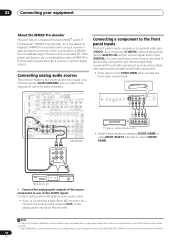
...for digital audio. Note 1 If your DVD player has multichannel analog outputs, you can connect it to one of the optical inputs on this receiver together with a TV and DVD player, with S-video or composite video connections. See also Connecting the multichannel analog inputs on the set-top ...on page 43. DIGITAL OUT R AUDIO L VIDEO AV OUT S-VIDEO 1 Connect the MONITOR OUT video jack to a video input on your DVD player to the DVD/LD AUDIO inputs. Connecting a satellite/cable receiver or other set-top box Satellite and cable receivers, and terrestrial digital TV tuners are all examples ...
...for digital audio. Note 1 If your DVD player has multichannel analog outputs, you can connect it to one of the optical inputs on this receiver together with a TV and DVD player, with S-video or composite video connections. See also Connecting the multichannel analog inputs on the set-top ...on page 43. DIGITAL OUT R AUDIO L VIDEO AV OUT S-VIDEO 1 Connect the MONITOR OUT video jack to a video input on your DVD player to the DVD/LD AUDIO inputs. Connecting a satellite/cable receiver or other set-top box Satellite and cable receivers, and terrestrial digital TV tuners are all examples ...

Owner's Manual
Page 14
...VCR2 outputs. 3 If the device can output digital audio, connect an optical-type3 digital audio output from your set up the receiver you'll need to tell the receiver which delivers a very stable, flicker-free picture. Use a stereo RCA/phono jack audio cable for the audio connection and a ...TV/SAT DVR/VCR1 AM LOOP L OUT PRE OUT CENTER L L IN 3 R SUB R SUR- OPTICAL COAXIAL DIGITAL OUT 3 R AUDIO L VIDEO AV IN S-VIDEO R AUDIO L AV OUT VIDEO S-VIDEO 12 DVR, VCR, etc. 1 Connect the audio/video outputs of audio/video inputs and outputs suitable for the video connection. •...
...VCR2 outputs. 3 If the device can output digital audio, connect an optical-type3 digital audio output from your set up the receiver you'll need to tell the receiver which delivers a very stable, flicker-free picture. Use a stereo RCA/phono jack audio cable for the audio connection and a ...TV/SAT DVR/VCR1 AM LOOP L OUT PRE OUT CENTER L L IN 3 R SUB R SUR- OPTICAL COAXIAL DIGITAL OUT 3 R AUDIO L VIDEO AV IN S-VIDEO R AUDIO L AV OUT VIDEO S-VIDEO 12 DVR, VCR, etc. 1 Connect the audio/video outputs of audio/video inputs and outputs suitable for the video connection. •...

Owner's Manual
Page 15
...OUT OPTICAL 2 DIGITAL IN CD-R, MD, DAT, etc. 1 Connect an optical-type1 digital audio output on your source to a set up the receiver (see The Input Assign menu on page 50. 2 Connect the COMPONENT VIDEO OUT jacks to the component video inputs on your TV or monitor. ...FRONT WOOFER OUT IN MONITO OUT OUT IN L DVR/VCR2 R FRONT MULTI C Y PB PR 2 COMPONENT VIDEO TV Connecting digital audio sources This receiver has both digital inputs and outputs, allowing you to connect digital audio components for playback and for the connection. 2 For recording equipment, connect the optical...
...OUT OPTICAL 2 DIGITAL IN CD-R, MD, DAT, etc. 1 Connect an optical-type1 digital audio output on your source to a set up the receiver (see The Input Assign menu on page 50. 2 Connect the COMPONENT VIDEO OUT jacks to the component video inputs on your TV or monitor. ...FRONT WOOFER OUT IN MONITO OUT OUT IN L DVR/VCR2 R FRONT MULTI C Y PB PR 2 COMPONENT VIDEO TV Connecting digital audio sources This receiver has both digital inputs and outputs, allowing you to connect digital audio components for playback and for the connection. 2 For recording equipment, connect the optical...
Owner's Manual
Page 16
Connecting analog audio sources This receiver features two stereo audio-only inputs. Connect using a coaxial or optical digital connection when connected to a WMA9 Pro-compatible player. Note that WMA9 Pro 96 ...
Connecting analog audio sources This receiver features two stereo audio-only inputs. Connect using a coaxial or optical digital connection when connected to a WMA9 Pro-compatible player. Note that WMA9 Pro 96 ...

Owner's Manual
Page 17
...to the left surround back terminal). You can connect just one surround back speaker if you plan to use speakers with the terminals on the receiver comprises a positive (+) and negative (-) terminal. IN 1 OPTICAL DIGITAL OUT MULTI-ROOM & SOURCE ROOM 2(ZONE 2) OUT IR IN ANTENNA... R FRONT SUB SUR- Front right LINE LEVEL INPUT CAUTION These speaker terminals carry HAZARDOUS LIVE voltage. To prevent the risk of the receiver's surround sound capabilities connect front, center, surround and surround back speakers, as well as a safety measure. 17 En SURROUND WOOFER ROUND...
...to the left surround back terminal). You can connect just one surround back speaker if you plan to use speakers with the terminals on the receiver comprises a positive (+) and negative (-) terminal. IN 1 OPTICAL DIGITAL OUT MULTI-ROOM & SOURCE ROOM 2(ZONE 2) OUT IR IN ANTENNA... R FRONT SUB SUR- Front right LINE LEVEL INPUT CAUTION These speaker terminals carry HAZARDOUS LIVE voltage. To prevent the risk of the receiver's surround sound capabilities connect front, center, surround and surround back speakers, as well as a safety measure. 17 En SURROUND WOOFER ROUND...

Owner's Manual
Page 20
...consumption to the AC outlet in order to avoid overheating and fire risk. Total electrical power consumption of equipment should be disconnected by the receiver's power switch. Caution • Do not connect a TV set, monitor, heater, or similar appliance to this type of connected ... Plug the power cord into a power outlet. 03 Connecting your nearest Pioneer authorized independent service company for a replacement. • The receiver should not be connected to the AC outlet. 20 En Plugging in the receiver Only plug in the cord or tie it damaged, ask your equipment Connecting...
...consumption to the AC outlet in order to avoid overheating and fire risk. Total electrical power consumption of equipment should be disconnected by the receiver's power switch. Caution • Do not connect a TV set, monitor, heater, or similar appliance to this type of connected ... Plug the power cord into a power outlet. 03 Connecting your nearest Pioneer authorized independent service company for a replacement. • The receiver should not be connected to the AC outlet. 20 En Plugging in the receiver Only plug in the cord or tie it damaged, ask your equipment Connecting...
Owner's Manual
Page 21
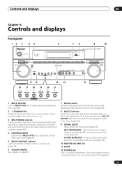
... - Controls and displays 04 Chapter 4: Controls and displays Front panel 12 3 45 STANDBY/ON PHASE CONTROL 6 78 9 10 AUDIO/VIDEO MULTI-CHANNEL RECEIVER VSX-80TXV MULTI ROOM LISTENING ON/OFF CONTROL MODE MULTI JOG DVD / LD TV /SAT DVR /VCR1 DVR / VCR2 VIDEO/GAME CD CD-R /... PHASE CONTROL indicator Lights when Basic Phase Control is switched on (page 10). 6 Character display See Display on page 23. 7 Remote sensor Receives the signals from the remote control (see Operating range of remote control unit on page 22). 8 MCACC indicator Lights when Acoustic Calibration EQ (...
... - Controls and displays 04 Chapter 4: Controls and displays Front panel 12 3 45 STANDBY/ON PHASE CONTROL 6 78 9 10 AUDIO/VIDEO MULTI-CHANNEL RECEIVER VSX-80TXV MULTI ROOM LISTENING ON/OFF CONTROL MODE MULTI JOG DVD / LD TV /SAT DVR /VCR1 DVR / VCR2 VIDEO/GAME CD CD-R /... PHASE CONTROL indicator Lights when Basic Phase Control is switched on (page 10). 6 Character display See Display on page 23. 7 Remote sensor Receives the signals from the remote control (see Operating range of remote control unit on page 22). 8 MCACC indicator Lights when Acoustic Calibration EQ (...

Owner's Manual
Page 22
... sensor. • Direct sunlight or fluorescent light is shining onto the remote sensor. • The receiver is located near a device that is emitting infrared rays. • The receiver is operated simultaneously with the MULTI JOG dial to memorize and name stations for recall (page 31). 21 SPEAKERS Use to change the speaker...
... sensor. • Direct sunlight or fluorescent light is shining onto the remote sensor. • The receiver is located near a device that is emitting infrared rays. • The receiver is operated simultaneously with the MULTI JOG dial to memorize and name stations for recall (page 31). 21 SPEAKERS Use to change the speaker...

Owner's Manual
Page 23
...according to the active sound processing feature. 9 TUNER indicators TUNED - SURROUND - STANDARD - When one of the Neo:6 modes of the receiver is being received in the corresponding format is detected. 4 OVER / ATT OVER lights to indicate Neo:6 processing (page 26). 15 Character display Displays various... (page 29). 8 Sound processing indicators Light according to which channels are active in stereo on page 26). 13 SLEEP Lights when the receiver is active (page 46). 6 VIDEO CONV. Lights when a Standard Surround mode is switched on (see Listening in digital sources. This lights...
...according to the active sound processing feature. 9 TUNER indicators TUNED - SURROUND - STANDARD - When one of the Neo:6 modes of the receiver is being received in the corresponding format is detected. 4 OVER / ATT OVER lights to indicate Neo:6 processing (page 26). 15 Character display Displays various... (page 29). 8 Sound processing indicators Light according to which channels are active in stereo on page 26). 13 SLEEP Lights when the receiver is active (page 46). 6 VIDEO CONV. Lights when a Standard Surround mode is switched on (see Listening in digital sources. This lights...


