Installation Manual
Page 2
...- If this equipment does cause harmful interference to radio or television reception, which the receiver is encouraged to try to Part 15 of this unit should be disposed of Digital Theater Systems, Inc. Consult the dealer or an experienced radio/TV technician for future reference... product or cords associated with accessories sold with the product will not occur in a residential installation. The cut-off and on this Pioneer product. D2-4-4-1_EF WARNING - D1-4-2-1_En WARNING: Handling the cord on , the user is connected. - D8-10-3a_En Manufactured ...
...- If this equipment does cause harmful interference to radio or television reception, which the receiver is encouraged to try to Part 15 of this unit should be disposed of Digital Theater Systems, Inc. Consult the dealer or an experienced radio/TV technician for future reference... product or cords associated with accessories sold with the product will not occur in a residential installation. The cut-off and on this Pioneer product. D2-4-4-1_EF WARNING - D1-4-2-1_En WARNING: Handling the cord on , the user is connected. - D8-10-3a_En Manufactured ...

Installation Manual
Page 4
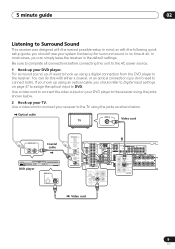
...area (MCACC 14 04 Connecting up Audio/Video cords 16 S-video cables 16 Component video cords 16 Digital audio coaxial cords/ Optical cables 16 Connecting digital components 17 Connecting audio components 18 Connecting DVD 5.1 channel components 18 Connecting video components 19 Connecting ...and B speaker systems 22 Hints on speaker placement 22 Connecting additional amplifiers 24 AC outlet 25 Operating other Pioneer components . . . . 25 Using this receiver with a Pioneer plasma display 26 05 Controls and displays Front panel 27 Display 29 Remote control 31 06 Listening to your...
...area (MCACC 14 04 Connecting up Audio/Video cords 16 S-video cables 16 Component video cords 16 Digital audio coaxial cords/ Optical cables 16 Connecting digital components 17 Connecting audio components 18 Connecting DVD 5.1 channel components 18 Connecting video components 19 Connecting ...and B speaker systems 22 Hints on speaker placement 22 Connecting additional amplifiers 24 AC outlet 25 Operating other Pioneer components . . . . 25 Using this receiver with a Pioneer plasma display 26 05 Controls and displays Front panel 27 Display 29 Remote control 31 06 Listening to your...

Installation Manual
Page 5
... . . 46 Subwoofer distance setting 46 Dynamic range control setting 47 Dual mono setting 47 Component video input settings 47 Digital input settings 47 SR+ control for Pioneer plasma displays 48 Manually calibrating your listening area (MCACC 49 Setting separate channel levels for listening modes 50 Using the SR...+ mode with a Pioneer plasma display 51 08 Using the tuner Listening to the radio 53 Improving FM stereo sound 53 Tuning directly to a station 53 ...
... . . 46 Subwoofer distance setting 46 Dynamic range control setting 47 Dual mono setting 47 Component video input settings 47 Digital input settings 47 SR+ control for Pioneer plasma displays 48 Manually calibrating your listening area (MCACC 49 Setting separate channel levels for listening modes 50 Using the SR...+ mode with a Pioneer plasma display 51 08 Using the tuner Listening to the radio 53 Improving FM stereo sound 53 Tuning directly to a station 53 ...
Installation Manual
Page 8
...system on page 35. 8 En Home theater refers to the use of multiple audio tracks to its size, quality, and ease of the receiver. DVD-Video has become the basic source material for realistic surround sound, but other possibilities (like you're in the middle of them ...be used to home theater systems that give you many more options (such as surround sound) when listening to your speaker setup. This receiver will automatically decode Dolby Digital, DTS, or Dolby Surround DVD-Video discs, according to soundtracks. 02 5 minute guide Chapter 2: 5 minute guide Introduction to home ...
...system on page 35. 8 En Home theater refers to the use of multiple audio tracks to its size, quality, and ease of the receiver. DVD-Video has become the basic source material for realistic surround sound, but other possibilities (like you're in the middle of them ...be used to home theater systems that give you many more options (such as surround sound) when listening to your speaker setup. This receiver will automatically decode Dolby Digital, DTS, or Dolby Surround DVD-Video discs, according to soundtracks. 02 5 minute guide Chapter 2: 5 minute guide Introduction to home ...
Installation Manual
Page 9
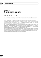
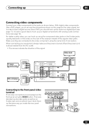
... video output on page 47 to assign the optical input to connect your TV. For surround sound, you should refer to Digital input settings on your DVD player to the receiver using the jacks shown below . Use a video cord to DVD. In most cases, you don't need to the AC power source.... 1 Hook up your system hooked up for surround sound in the default settings. Optical cable TV VIDEO IN Video cord DIGITAL OUT Coaxial cable STANDBY...
... video output on page 47 to assign the optical input to connect your TV. For surround sound, you should refer to Digital input settings on your DVD player to the receiver using the jacks shown below . Use a video cord to DVD. In most cases, you don't need to the AC power source.... 1 Hook up your system hooked up for surround sound in the default settings. Optical cable TV VIDEO IN Video cord DIGITAL OUT Coaxial cable STANDBY...
Installation Manual
Page 10
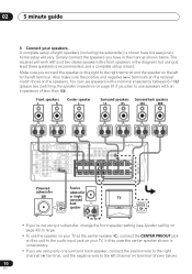
... not using at least three speakers is recommended, and a complete setup is best. The receiver will vary. Front speakers L R Center speaker C Surround speakers Surround back speakers LS RS SBL SBR CENTER IN DIGITAL OUT OPT IN AUX COMPONENT VIDEO ASSIGNABLE FM UNBAL AM CD 75 Ω LOOP ANTENNA ...R MONITOR OUT L MONITOR OUT OUT SURROUND L L SURROU BA OPT 2 OUT (DVR/VCR) IN OPT 1 ASSIGNABLE DIGITAL IN (TV / SA T ) IN COAX 2 (CD) IN COAX 1 (DVD OUT /LD) DVR/ VCR IN TV / SA T IN DVD /LD FRONT D V D 5....
... not using at least three speakers is recommended, and a complete setup is best. The receiver will vary. Front speakers L R Center speaker C Surround speakers Surround back speakers LS RS SBL SBR CENTER IN DIGITAL OUT OPT IN AUX COMPONENT VIDEO ASSIGNABLE FM UNBAL AM CD 75 Ω LOOP ANTENNA ...R MONITOR OUT L MONITOR OUT OUT SURROUND L L SURROU BA OPT 2 OUT (DVR/VCR) IN OPT 1 ASSIGNABLE DIGITAL IN (TV / SA T ) IN COAX 2 (CD) IN COAX 1 (DVD OUT /LD) DVR/ VCR IN TV / SA T IN DVD /LD FRONT D V D 5....

Installation Manual
Page 11
See Listening to your system on page 35 for more setup options. • Depending on your DVD player or source discs, you may only get digital 2 channel stereo and analog sound. Check the manual that came with the TV if you don't know how to your subwoofer and the TV. Also ... speaker setup, room size and listening position. Make sure you've set the receiver to the DVD input. 5 Press QUICK SETUP on the front panel to this . If it on page 12 if you're unsure about the settings. VSX-D914 model only - 5 minute guide 02 • If you select subwoofer (SB SW...
See Listening to your system on page 35 for more setup options. • Depending on your DVD player or source discs, you may only get digital 2 channel stereo and analog sound. Check the manual that came with the TV if you don't know how to your subwoofer and the TV. Also ... speaker setup, room size and listening position. Make sure you've set the receiver to the DVD input. 5 Press QUICK SETUP on the front panel to this . If it on page 12 if you're unsure about the settings. VSX-D914 model only - 5 minute guide 02 • If you select subwoofer (SB SW...
Installation Manual
Page 14
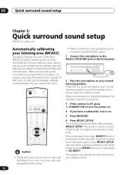
... mic about ear level at your normal listening position. DVD/LD TV/SAT DVR/VCR TVCONT MULTI CONTROL CD CD-R/TAPE TUNER RECEIVER 3 If the receiver is off, press STANDBY/ON to turn it on a table or chair. The system outputs a series of test tones to... FL DIMMER MCACC SETUP MIC DIGITAL IN VIDEO INPUT S-VIDEO VIDEO L AUDIO R MULTI JOG 2 Place the microphone at your normal listening position using the supplied microphone stand on . 5 Press RECEIVER. 03 Quick surround sound setup Chapter 3: Quick surround sound setup VSX-D914 model only Automatically calibrating your listening...
... mic about ear level at your normal listening position. DVD/LD TV/SAT DVR/VCR TVCONT MULTI CONTROL CD CD-R/TAPE TUNER RECEIVER 3 If the receiver is off, press STANDBY/ON to turn it on a table or chair. The system outputs a series of test tones to... FL DIMMER MCACC SETUP MIC DIGITAL IN VIDEO INPUT S-VIDEO VIDEO L AUDIO R MULTI JOG 2 Place the microphone at your normal listening position using the supplied microphone stand on . 5 Press RECEIVER. 03 Quick surround sound setup Chapter 3: Quick surround sound setup VSX-D914 model only Automatically calibrating your listening...
Installation Manual
Page 16
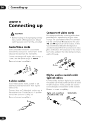
...video cords to the component video jacks on the video component you are hooking up . In this receiver. Connect from the component video jacks on the video component you are used to connect digital components to connect the monitor TV. Y Green Blue P B P R Red S-video cables Use... yellow plugs to insert completely. The color signal of the receiver to an S-video jack on the rear of your video source. Be sure to insert completely. S VIDEO Digital audio coaxial cords/ Optical cables Commercially available digital audio coaxial cords (standard video cords can also be used)...
...video cords to the component video jacks on the video component you are hooking up . In this receiver. Connect from the component video jacks on the video component you are used to connect digital components to connect the monitor TV. Y Green Blue P B P R Red S-video cables Use... yellow plugs to insert completely. The color signal of the receiver to an S-video jack on the rear of your video source. Be sure to insert completely. S VIDEO Digital audio coaxial cords/ Optical cables Commercially available digital audio coaxial cords (standard video cords can also be used)...
Installation Manual
Page 17
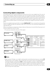
... optical inputs) on the connection). We also recommend hooking up your equipment, always make direct digital recordings with like (for surround sound is a matter of matching like with this receiver for example, the coaxial output from the AC outlet. • The arrows indicate the direction... of the signal. CD recorder DIGITAL OUT DIGITAL IN Satellite tuner CD player DIGITAL OUT DIGITAL OUT COAX IN DIGITAL OUT OPT IN AUX FM UNBAL 75 ...
... optical inputs) on the connection). We also recommend hooking up your equipment, always make direct digital recordings with like (for surround sound is a matter of matching like with this receiver for example, the coaxial output from the AC outlet. • The arrows indicate the direction... of the signal. CD recorder DIGITAL OUT DIGITAL IN Satellite tuner CD player DIGITAL OUT DIGITAL OUT COAX IN DIGITAL OUT OPT IN AUX FM UNBAL 75 ...
Installation Manual
Page 18
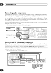
...a decoder or a DVD player with multi-channel analog outputs to the multi-channel inputs of this receiver. See page 17 for more on digital connections. CD player OUTPUT L R CD-R/Tape/MD deck REC PLAY IN DIGITAL OUT OPT IN AUX FM UNBAL 75 Ω CD OPT 2 OUT DVR/ VCR (DVR/VCR)... indicate the direction of the audio signal. When connecting your analog audio components (such as a cassette deck) to the jacks. When connecting your digital components to analog audio jacks if you can only be used when DVD 5.1 ch is disconnected from analog components. Note that only play, you ...
...a decoder or a DVD player with multi-channel analog outputs to the multi-channel inputs of this receiver. See page 17 for more on digital connections. CD player OUTPUT L R CD-R/Tape/MD deck REC PLAY IN DIGITAL OUT OPT IN AUX FM UNBAL 75 Ω CD OPT 2 OUT DVR/ VCR (DVR/VCR)... indicate the direction of the audio signal. When connecting your analog audio components (such as a cassette deck) to the jacks. When connecting your digital components to analog audio jacks if you can only be used when DVD 5.1 ch is disconnected from analog components. Note that only play, you ...
Installation Manual
Page 19
...same way you must use the connections shown on the rear of the receiver instead of the regular video jacks. Hook them up the audio to a digital input (see page 18). When connecting your digital components with analog audio connections (see page 17). It is disconnected from... STEREO/ DIRECT SIGNAL MIDNIGHT/ SELECT LOUDNESS SPEAKERS SB CH MODE MULTI JOG TONE QUICK SETUP ODE MCACC VIDEO INPUT SETUP MIC DIGITAL IN S-VIDEO VIDEO L AUDIO R VSX-D914 DIGITAL OUT V L R VIDEO OUTPUT Video camera (etc.) 19 En There are accessed via the front panel using the VIDEO button...
...same way you must use the connections shown on the rear of the receiver instead of the regular video jacks. Hook them up the audio to a digital input (see page 18). When connecting your digital components with analog audio connections (see page 17). It is disconnected from... STEREO/ DIRECT SIGNAL MIDNIGHT/ SELECT LOUDNESS SPEAKERS SB CH MODE MULTI JOG TONE QUICK SETUP ODE MCACC VIDEO INPUT SETUP MIC DIGITAL IN S-VIDEO VIDEO L AUDIO R VSX-D914 DIGITAL OUT V L R VIDEO OUTPUT Video camera (etc.) 19 En There are accessed via the front panel using the VIDEO button...
Installation Manual
Page 20
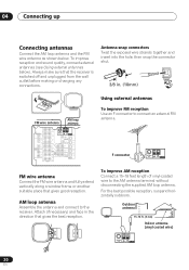
...face in . (10mm) Using external antennas FM wire antenna AM loop antenna IN DIGITAL OUT OPT IN AUX FM UNBAL 75 Ω CD OPT 2 OUT DVR/ VCR (DVR/VCR) IN OPT 1 ...ASSIGNABLE DIGITAL IN (TV / SA T ) IN COAX 2 (CD) IN COAX 1 (DVD OUT /LD) IN TV / SA T IN DVD... Connect the FM wire antenna and fully extend vertically along a window frame or another suitable place that the receiver is switched off and unplugged from the wall outlet before making or changing any connections. Outdoor antenna 15-18...
...face in . (10mm) Using external antennas FM wire antenna AM loop antenna IN DIGITAL OUT OPT IN AUX FM UNBAL 75 Ω CD OPT 2 OUT DVR/ VCR (DVR/VCR) IN OPT 1 ...ASSIGNABLE DIGITAL IN (TV / SA T ) IN COAX 2 (CD) IN COAX 1 (DVD OUT /LD) IN TV / SA T IN DVD... Connect the FM wire antenna and fully extend vertically along a window frame or another suitable place that the receiver is switched off and unplugged from the wall outlet before making or changing any connections. Outdoor antenna 15-18...
Installation Manual
Page 21
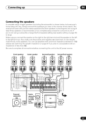
... the speaker impedance on the left terminal. Front speakers L R Center speaker C Surround speakers Surround back speakers LS RS SBL SBR CENTER IN DIGITAL OUT OPT IN AUX COMPONENT VIDEO ASSIGNABLE FM UNBAL AM CD 75 Ω LOOP ANTENNA R MONITOR OUT L MONITOR OUT OUT SURROUND L L... less than 8Ω). You can use speakers with a nominal impedance between 6-16Ω (please see Speaker setting on the speakers. The receiver will vary. Simply connect the speakers you 're not using at least three speakers is recommended, and a complete setup is shown below ....
... the speaker impedance on the left terminal. Front speakers L R Center speaker C Surround speakers Surround back speakers LS RS SBL SBR CENTER IN DIGITAL OUT OPT IN AUX COMPONENT VIDEO ASSIGNABLE FM UNBAL AM CD 75 Ω LOOP ANTENNA R MONITOR OUT L MONITOR OUT OUT SURROUND L L... less than 8Ω). You can use speakers with a nominal impedance between 6-16Ω (please see Speaker setting on the speakers. The receiver will vary. Simply connect the speakers you 're not using at least three speakers is recommended, and a complete setup is shown below ....
Installation Manual
Page 24
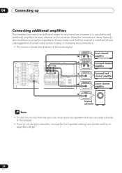
... UNBAL AM SIGNABLE / LD) IN ¥ L L SURROUND BACK CD 75 Ω LOOP ANTENNA MONITOR OUT OUT OPT 2 OUT DVR/ VCR (DVR/VCR) IN OPT 1 ASSIGNABLE DIGITAL IN (TV / SA T ) IN COAX 2 (CD) IN COAX 1 (DVD OUT /LD) IN TV / SA T IN DVD /LD FRONT D V D 5.1CH REC INPUT CD-R IN... Center channel amplifier INPUT Powered subwoofer • To hear sound only from the wall outlet before making or changing any speakers that the receiver is possible to add additional amplifiers to power your speakers. Make the connections shown below to add amplifiers to every channel on page 43...
... UNBAL AM SIGNABLE / LD) IN ¥ L L SURROUND BACK CD 75 Ω LOOP ANTENNA MONITOR OUT OUT OPT 2 OUT DVR/ VCR (DVR/VCR) IN OPT 1 ASSIGNABLE DIGITAL IN (TV / SA T ) IN COAX 2 (CD) IN COAX 1 (DVD OUT /LD) IN TV / SA T IN DVD /LD FRONT D V D 5.1CH REC INPUT CD-R IN... Center channel amplifier INPUT Powered subwoofer • To hear sound only from the wall outlet before making or changing any speakers that the receiver is possible to add additional amplifiers to power your speakers. Make the connections shown below to add amplifiers to every channel on page 43...
Installation Manual
Page 26
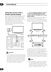
...JOG TV/SAT AUDIO IN AUDIO/VIDEO MULTI-CHANNEL RECEIVER VSX-D914 TUNING ADVANCED STANDARD SURROUND STEREO/ DIRECT SIGNAL SELECT MIDNIGHT/ LOUDNESS SPEAKERS SB CH MODE MULTI JOG TONE QUICK SETUP BAND LISTENING MODE MPX INPUT ATT FL DIMMER MCACC SETUP MIC DIGITAL IN VIDEO INPUT S-VIDEO VIDEO L AUDIO R... displays on page 48 for more information on obtaining an SR+ cable. 26 En 04 Connecting up Using this receiver with a Pioneer plasma display If you have a Pioneer plasma display (models PRO-1110HD, PRO-910HD, PDP-5040HD, PDP-4340HD), you can use an SR+ cable (see note ...
...JOG TV/SAT AUDIO IN AUDIO/VIDEO MULTI-CHANNEL RECEIVER VSX-D914 TUNING ADVANCED STANDARD SURROUND STEREO/ DIRECT SIGNAL SELECT MIDNIGHT/ LOUDNESS SPEAKERS SB CH MODE MULTI JOG TONE QUICK SETUP BAND LISTENING MODE MPX INPUT ATT FL DIMMER MCACC SETUP MIC DIGITAL IN VIDEO INPUT S-VIDEO VIDEO L AUDIO R... displays on page 48 for more information on obtaining an SR+ cable. 26 En 04 Connecting up Using this receiver with a Pioneer plasma display If you have a Pioneer plasma display (models PRO-1110HD, PRO-910HD, PDP-5040HD, PDP-4340HD), you can use an SR+ cable (see note ...
Installation Manual
Page 27
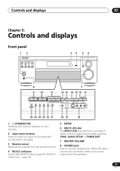
... Front panel 12 DVD/LD TV/SAT DVR/VCR VIDEO CD-R/ CD TAPE/MD TUNER AUX STANDBY/ON PHONES 34 5 6 AUDIO/VIDEO MULTI-CHANNEL RECEIVER VSX-D914 ENTER MULTI JOG MASTER VOLUME DOWN UP 8 7 9 10 11 12 13 14 15 16 17 STATION TUNING ADVANCED STEREO/ STANDARD SURROUND DIRECT SIGNAL ... MCACC SETUP MIC DIGITAL IN VIDEO INPUT S-VIDEO VIDEO L AUDIO R MULTI JOG 26 25 24 23 22 21 20 19 18 1 STANDBY/ON Switches the receiver between on and standby. 2 Input select buttons Press to connect headphones. Use it to select options after MCACC setup (page 49, VSX-D914 model only - ...
... Front panel 12 DVD/LD TV/SAT DVR/VCR VIDEO CD-R/ CD TAPE/MD TUNER AUX STANDBY/ON PHONES 34 5 6 AUDIO/VIDEO MULTI-CHANNEL RECEIVER VSX-D914 ENTER MULTI JOG MASTER VOLUME DOWN UP 8 7 9 10 11 12 13 14 15 16 17 STATION TUNING ADVANCED STEREO/ STANDARD SURROUND DIRECT SIGNAL ... MCACC SETUP MIC DIGITAL IN VIDEO INPUT S-VIDEO VIDEO L AUDIO R MULTI JOG 26 25 24 23 22 21 20 19 18 1 STANDBY/ON Switches the receiver between on and standby. 2 Input select buttons Press to connect headphones. Use it to select options after MCACC setup (page 49, VSX-D914 model only - ...
Installation Manual
Page 28
...12. 18 VIDEO INPUT See Connecting to the front panel video terminal on page 19. 19 DIGITAL IN See Connecting to the front panel video terminal on page 19. 20 MCACC SETUP MIC (VSX-D914 model only) Connect the microphone supplied with your system to the MCACC SETUP MIC jack when ...ADVANCED SURROUND Use to cycle through the speaker system: A B A+B (page 22). STEREO/DIRECT Switches between the various surround modes (page 35). Use Loudness to receive a radio broadcast in mono (page 53). 24 BAND Switches between AM and FM radio bands (page 53). 25 CLASS Switches between the various Pro Logic...
...12. 18 VIDEO INPUT See Connecting to the front panel video terminal on page 19. 19 DIGITAL IN See Connecting to the front panel video terminal on page 19. 20 MCACC SETUP MIC (VSX-D914 model only) Connect the microphone supplied with your system to the MCACC SETUP MIC jack when ...ADVANCED SURROUND Use to cycle through the speaker system: A B A+B (page 22). STEREO/DIRECT Switches between the various surround modes (page 35). Use Loudness to receive a radio broadcast in mono (page 53). 24 BAND Switches between AM and FM radio bands (page 53). 25 CLASS Switches between the various Pro Logic...

Installation Manual
Page 29
...when a signal with DTS encoded audio signals is detected. 2 When the STANDARD mode of the receiver is on, this lights to indicate decoding of a DTS signal. 3 2 DIGITAL When the STANDARD mode of the receiver is on, this lights to indicate the type of a source. 7 MIDNIGHT Lights during Virtual surround... the speaker system currently in surround sound on , this lights to indicate decoding of a Dolby Digital signal. 4 2 PRO LOGIC II (x) When the (STANDARD) Pro Logic II mode of the receiver is on page 35 for the most accurate reproduction of input signal assigned for the current component:...
...when a signal with DTS encoded audio signals is detected. 2 When the STANDARD mode of the receiver is on, this lights to indicate decoding of a DTS signal. 3 2 DIGITAL When the STANDARD mode of the receiver is on, this lights to indicate the type of a source. 7 MIDNIGHT Lights during Virtual surround... the speaker system currently in surround sound on , this lights to indicate decoding of a Dolby Digital signal. 4 2 PRO LOGIC II (x) When the (STANDARD) Pro Logic II mode of the receiver is on page 35 for the most accurate reproduction of input signal assigned for the current component:...
Installation Manual
Page 31
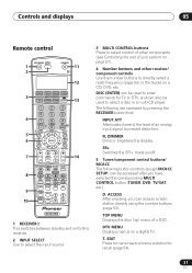
...directly using the number buttons (page 53). SR+ Switches the SR+ mode on a digital TV. DTV MENU Displays menus on /off. 5 Tuner/component control buttons/ MCACC The following are accessed by pressing the RECEIVER button first: INPUT ATT Attenuates (lowers) the level of an analog input signal to...pressing, you have selected the corresponding MULTI CONTROL button (TUNER, DVD, TV/SAT, etc.) D. EDIT Press to memorize and name a station for this receiver. 2 INPUT SELECT Use to select the input source. 3 MULTI CONTROL buttons Press to directly select a radio frequency (page 53) or the tracks on...
...directly using the number buttons (page 53). SR+ Switches the SR+ mode on a digital TV. DTV MENU Displays menus on /off. 5 Tuner/component control buttons/ MCACC The following are accessed by pressing the RECEIVER button first: INPUT ATT Attenuates (lowers) the level of an analog input signal to...pressing, you have selected the corresponding MULTI CONTROL button (TUNER, DVD, TV/SAT, etc.) D. EDIT Press to memorize and name a station for this receiver. 2 INPUT SELECT Use to select the input source. 3 MULTI CONTROL buttons Press to directly select a radio frequency (page 53) or the tracks on...

