Owner's Manual
Page 2
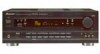
.... This is located on your model properly. THE POWER SWITCH IS SECONDARY CONNECTED AND THEREFORE DOES NOT SEPARATE THE UNIT FROM MAINS POWER IN THE STANDBY POSITION. Connect the equipment into an outlet on , the user is connected. - To Change Channel Steps With the power turned OFF, hold the ...and AM 10 kHz. NO USER-SERVICEABLE PARTS INSIDE. For this reason, be of sufficient magnitude to constitute a risk of electric shock to this Pioneer product. FM 100 kHz, AM 10 kHz: Set to confirm that to turn the power ON. • Each time the above operation is performed...
.... This is located on your model properly. THE POWER SWITCH IS SECONDARY CONNECTED AND THEREFORE DOES NOT SEPARATE THE UNIT FROM MAINS POWER IN THE STANDBY POSITION. Connect the equipment into an outlet on , the user is connected. - To Change Channel Steps With the power turned OFF, hold the ...and AM 10 kHz. NO USER-SERVICEABLE PARTS INSIDE. For this reason, be of sufficient magnitude to constitute a risk of electric shock to this Pioneer product. FM 100 kHz, AM 10 kHz: Set to confirm that to turn the power ON. • Each time the above operation is performed...
Owner's Manual
Page 3
...in any kind into the outlet, contact your obsolete outlet. POWERSOURCES -This product should be retained for long periods of antenna-discharge unit, connection to an antenna discharge unit, size of grounding conductors, location of time, unplug it can result in performance - The power cord of...sources such as radiators, heat registers, stoves, or other hazards. OUTDOOR ANTENNA GROUNDING - If an outside antenna or cable system is connected to the product, be located in the vicinity of any service or repairs to this product through openings as opening or removing covers ...
...in any kind into the outlet, contact your obsolete outlet. POWERSOURCES -This product should be retained for long periods of antenna-discharge unit, connection to an antenna discharge unit, size of grounding conductors, location of time, unplug it can result in performance - The power cord of...sources such as radiators, heat registers, stoves, or other hazards. OUTDOOR ANTENNA GROUNDING - If an outside antenna or cable system is connected to the product, be located in the vicinity of any service or repairs to this product through openings as opening or removing covers ...
Owner's Manual
Page 4
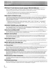
... When late night hours or other factors require that enhance DTS and Dolby audio performance by recalling the appropriate preset code. Connections can be used to operate a variety of each channel for true high fidelity reproduction from Digital Theater Systems, Inc. This...only) surround sound. DIGITAL NR function (VSX-D608 only) Noise in the playback source can enjoy Dolby Pro Logic encoded software in theaters. Optical Digital Output The digital signal input can enjoy a clearer sound. 5.1 Channel Input By connecting components equipped with 5.1 channel analog output jacks...
... When late night hours or other factors require that enhance DTS and Dolby audio performance by recalling the appropriate preset code. Connections can be used to operate a variety of each channel for true high fidelity reproduction from Digital Theater Systems, Inc. This...only) surround sound. DIGITAL NR function (VSX-D608 only) Noise in the playback source can enjoy Dolby Pro Logic encoded software in theaters. Optical Digital Output The digital signal input can enjoy a clearer sound. 5.1 Channel Input By connecting components equipped with 5.1 channel analog output jacks...
Owner's Manual
Page 5
Introductory Information Checking the Supplied Accessories How to Use This Manual Preparing the Remote Control Receiver Installation When Making Cable Connections Connections Antennas Audio Components Connections Video Components Connections Digital Connections DVD 5.1 Channel Connection Speakers Preparations Setting Up for Surround Sound Setting Up the Remote Control Clearing the Remote Control Settings Names of Parts and Basic Operations...
Introductory Information Checking the Supplied Accessories How to Use This Manual Preparing the Remote Control Receiver Installation When Making Cable Connections Connections Antennas Audio Components Connections Video Components Connections Digital Connections DVD 5.1 Channel Connection Speakers Preparations Setting Up for Surround Sound Setting Up the Remote Control Clearing the Remote Control Settings Names of Parts and Basic Operations...
Owner's Manual
Page 6
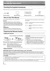
...Switching this receiver. 6 Indicates a blinking button, indicator, or display. \ I Indicates a steadily lit button, indicator, or i i i - When connecting components to set up and customize your other audio and video components. Checking the Supplied Accessories Please check that you notice a decrease in the operating...This manual is recommended that you have different voltages. memo When changing the batteries, it in standby also switches components connected to the receiver's AC OUTLET jacks on , they consume a large amount of the batteries properly according to the ...
...Switching this receiver. 6 Indicates a blinking button, indicator, or display. \ I Indicates a steadily lit button, indicator, or i i i - When connecting components to set up and customize your other audio and video components. Checking the Supplied Accessories Please check that you notice a decrease in the operating...This manual is recommended that you have different voltages. memo When changing the batteries, it in standby also switches components connected to the receiver's AC OUTLET jacks on , they consume a large amount of the batteries properly according to the ...
Owner's Manual
Page 7
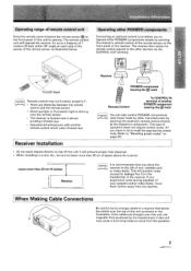
...cause a humming noise to come from the speakers. 7 ,ARR71c7, This type of another remote control which uses infrared rays. When Making Cable Connections Be careful not to arrange cables in a manner that you have to do is located near a device emitting infrared rays. • Operated.... This will operate the receiver for up to the other manufacturers) by other devices via the CONTROL OUT terminal. Operating other PIONEER components Connecting an optional control cord allows you experience noise during playback of your cassette and/ or video decks. If you to "Recalling preset...
...cause a humming noise to come from the speakers. 7 ,ARR71c7, This type of another remote control which uses infrared rays. When Making Cable Connections Be careful not to arrange cables in a manner that you have to do is located near a device emitting infrared rays. • Operated.... This will operate the receiver for up to the other manufacturers) by other devices via the CONTROL OUT terminal. Operating other PIONEER components Connecting an optional control cord allows you experience noise during playback of your cassette and/ or video decks. If you to "Recalling preset...

Owner's Manual
Page 8
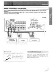
Antennas FM wire antenna Connect the FM wire antenna and fully extend (for best reception, attach horizontally along a window frame, etc.). AM loop antenna (See below) NOTE: In this section, the area within dotted line only applies to the VSX-D608. • NINA r DIGITALIN M OCT pCI0/ DO /DES UNREAL J., J., LOOP 75a ANTENNA 52... RzET0 0* ! 0 IN cfi ) a pswoo 19 0 0 °IG~°`~ 0000000 OO O Um) afo EAD/TAPE 1---"-00-, TAPE 2 MONITOR SAT r;7 : :5; ,,, VCR 'I REMIT SPEAKERS 0 R0 OL Ct • VSX-D608 O O SB CENTER PREOUT fav R L R 5 5 O -RWUI TION SPEAI
Antennas FM wire antenna Connect the FM wire antenna and fully extend (for best reception, attach horizontally along a window frame, etc.). AM loop antenna (See below) NOTE: In this section, the area within dotted line only applies to the VSX-D608. • NINA r DIGITALIN M OCT pCI0/ DO /DES UNREAL J., J., LOOP 75a ANTENNA 52... RzET0 0* ! 0 IN cfi ) a pswoo 19 0 0 °IG~°`~ 0000000 OO O Um) afo EAD/TAPE 1---"-00-, TAPE 2 MONITOR SAT r;7 : :5; ,,, VCR 'I REMIT SPEAKERS 0 R0 OL Ct • VSX-D608 O O SB CENTER PREOUT fav R L R 5 5 O -RWUI TION SPEAI
Owner's Manual
Page 9
r-- CONTROL GIO . TAPE 54TH JNROR✓~ LD e VCR 2 POINT SPEAXERS CD R O O L Th VSX-D608 0 CENTER PRECUT SUB WOOFER PREOUT gUERE-, - %LAMP, SCAPUATRIOEPN: RD 02;1 CAUTION: mixmurnwwxuu r :L1ETS/T7:87/ IMPEDANCE SELECTORS V ■ RC D PLAY REC MD recorder or... OLR O O VIDEO nuT IN atD MD PE ZED CO -•"- Cassette Deck Installment Depending on page 11 when making digital connections from your DVD or LD player. If you make or change connections. Refer to "Digital Connections" on where the cassette deck is caused by leakage flux from the transformer in the receiver...
r-- CONTROL GIO . TAPE 54TH JNROR✓~ LD e VCR 2 POINT SPEAXERS CD R O O L Th VSX-D608 0 CENTER PRECUT SUB WOOFER PREOUT gUERE-, - %LAMP, SCAPUATRIOEPN: RD 02;1 CAUTION: mixmurnwwxuu r :L1ETS/T7:87/ IMPEDANCE SELECTORS V ■ RC D PLAY REC MD recorder or... OLR O O VIDEO nuT IN atD MD PE ZED CO -•"- Cassette Deck Installment Depending on page 11 when making digital connections from your DVD or LD player. If you make or change connections. Refer to "Digital Connections" on where the cassette deck is caused by leakage flux from the transformer in the receiver...
Owner's Manual
Page 10
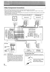
... "S2" is printed on the S-Video jacks on the rear panel, S, S1 and S2 S-video connection can be off and the power cord unpluged. • Connect your TV monitor or video camera via the S-Video jack (VSX-D608 only). (VSX-D608 only) TV monitor Le Video deck (1) Video deck (2) INPUT `V 0 SVIOE0 t "-ANTENNA DIGOITPNRATCL/MDDOT...
... "S2" is printed on the S-Video jacks on the rear panel, S, S1 and S2 S-video connection can be off and the power cord unpluged. • Connect your TV monitor or video camera via the S-Video jack (VSX-D608 only). (VSX-D608 only) TV monitor Le Video deck (1) Video deck (2) INPUT `V 0 SVIOE0 t "-ANTENNA DIGOITPNRATCL/MDDOT...
Owner's Manual
Page 11
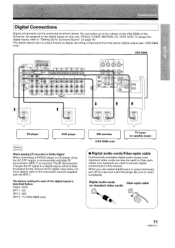
... the VSX-D508) of the digital inputs is then processed by the receiver at the digital input jacks. Digital audio cords Fiber-optic cable (or standard video cords) 0 11 When you use optical digital input or output terminals, pull off the caps and insert the plugs. Digital Connections Digital ...standard video cords can select up to four (three on page 16) The digital signal input is required. You can also be connected as shown below . Be sure to digital recording components from the optical digital output jack. (VSX-D608 only) VSX-D608 DIGO-AL IN OPT RCM/ DO /SOS r -
... the VSX-D508) of the digital inputs is then processed by the receiver at the digital input jacks. Digital audio cords Fiber-optic cable (or standard video cords) 0 11 When you use optical digital input or output terminals, pull off the caps and insert the plugs. Digital Connections Digital ...standard video cords can select up to four (three on page 16) The digital signal input is required. You can also be connected as shown below . Be sure to digital recording components from the optical digital output jack. (VSX-D608 only) VSX-D608 DIGO-AL IN OPT RCM/ DO /SOS r -

Owner's Manual
Page 12
...em-lisova rt.,;6 ss SPEAKER, il/nGAN w SPFAKEq ECI IMPEDANCE SELECTOR -• VSX-D608 SURROUND OUTPUT L CENTER SUB WOOFER FRONT 'OUTPUT VIDEO OUT art • .___ , •-____. DVD 5.1 Channel Connection DVD and LD discs are often compatible with 5.1 analog outputs to switch between the ... Components equipped with 5.1 channel analogue output jacks memo The 5.1 channel input can be used when DVD/LD is selected. 12 Connections can only be made from a DVD player, Dolby Digital decoder, or DTS decoder equipped with both 2 channel and 5.1 channel audio output formats.
...em-lisova rt.,;6 ss SPEAKER, il/nGAN w SPFAKEq ECI IMPEDANCE SELECTOR -• VSX-D608 SURROUND OUTPUT L CENTER SUB WOOFER FRONT 'OUTPUT VIDEO OUT art • .___ , •-____. DVD 5.1 Channel Connection DVD and LD discs are often compatible with 5.1 analog outputs to switch between the ... Components equipped with 5.1 channel analogue output jacks memo The 5.1 channel input can be used when DVD/LD is selected. 12 Connections can only be made from a DVD player, Dolby Digital decoder, or DTS decoder equipped with both 2 channel and 5.1 channel audio output formats.
Owner's Manual
Page 13
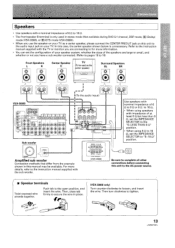
... Speaker C TV (To be used in stereo mode (Not available during DVD 5.1 channel, DSP mode, 1717 (Dolby) mode (VSX-D508), or DO /DTS mode (VSX-D608)). • When you are connecting to for more information. • You can set the configuration of your speaker system, whether the sizes of 652 to the...as the center speaker) Surround Speakers SL SR O VSX-D608 °MALIN 1- '7 EEER1 th thrg: SR is unnecessary. A (75)cD)co TR L In this unit to 16 Q. • The front speaker B terminal is only used as a center speaker, please connect the CENTER PREOUT jack on this case, the ...
... Speaker C TV (To be used in stereo mode (Not available during DVD 5.1 channel, DSP mode, 1717 (Dolby) mode (VSX-D508), or DO /DTS mode (VSX-D608)). • When you are connecting to for more information. • You can set the configuration of your speaker system, whether the sizes of 652 to the...as the center speaker) Surround Speakers SL SR O VSX-D608 °MALIN 1- '7 EEER1 th thrg: SR is unnecessary. A (75)cD)co TR L In this unit to 16 Q. • The front speaker B terminal is only used as a center speaker, please connect the CENTER PREOUT jack on this case, the ...
Owner's Manual
Page 14
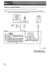
.... (e.g. i, L SUBWNIFER DIGITAL OUT ==M/o0 DIGIT;L'r o 9r I ---' ORR.. TO morvrroR S2: , . Connecting additional amplifiers To use separate amplifiers to the CENTER SPEAKER terminal.) PIONEER projection TV (for center channel) O Li L-Audio IN (MONO) Amplifier (for center channel) (or) IN ...Amplified sub woofer 0 VSX-D608 r - Do not connect a separate power amplifier to the CENTER PREOUT jack if you have already connected a center speaker...
.... (e.g. i, L SUBWNIFER DIGITAL OUT ==M/o0 DIGIT;L'r o 9r I ---' ORR.. TO morvrroR S2: , . Connecting additional amplifiers To use separate amplifiers to the CENTER SPEAKER terminal.) PIONEER projection TV (for center channel) O Li L-Audio IN (MONO) Amplifier (for center channel) (or) IN ...Amplified sub woofer 0 VSX-D608 r - Do not connect a separate power amplifier to the CENTER PREOUT jack if you have already connected a center speaker...

Owner's Manual
Page 15
..., place the speakers farther away from the listening position than the front and center speakers. CAUTION: When installing the center speaker on top of connected components should not exceed 100W (0.8 A) (Multi-Voltage model: 100 W MAX). Front Left Sub Woofer Center Front Right Surround Left O 0 ...8226; When installing speakers near the TV, we recommend using magnetically shielded speakers to prevent accidents and improve sound quality. When connecting components to secure it may lead to endangering those nearby or damaging the speaker. • If possible, install the surround ...
..., place the speakers farther away from the listening position than the front and center speakers. CAUTION: When installing the center speaker on top of connected components should not exceed 100W (0.8 A) (Multi-Voltage model: 100 W MAX). Front Left Sub Woofer Center Front Right Surround Left O 0 ...8226; When installing speakers near the TV, we recommend using magnetically shielded speakers to prevent accidents and improve sound quality. When connecting components to secure it may lead to endangering those nearby or damaging the speaker. • If possible, install the surround ...
Owner's Manual
Page 16
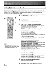
... to the optical digital input 1. Coaxial digital input setting (page 20) Use to specify the input to be sure to select the setting you have connected. Optical digital input 1 setting (page 20) Use to specify the input to be assigned to the optical digital input 3. 4 Press A or o to complete the ...following pages for detailed descriptions of the settings available for 20 seconds. Optical digital input 3 setting (page 21) (VSX-D608 only) Use to specify the input to be assigned to compress the dynamic range of your front speaker.
... to the optical digital input 1. Coaxial digital input setting (page 20) Use to specify the input to be sure to select the setting you have connected. Optical digital input 1 setting (page 20) Use to specify the input to be assigned to the optical digital input 3. 4 Press A or o to complete the ...following pages for detailed descriptions of the settings available for 20 seconds. Optical digital input 3 setting (page 21) (VSX-D608 only) Use to specify the input to be assigned to compress the dynamic range of your front speaker.

Owner's Manual
Page 17
C. -- 73 lea * Press >> to advance to Small. Front speaker (initial setting is "L (Large)") • Select "FL" if your speaker is connected. J. 3. -8 Ids I ".L. -- L. -- Speaker size is denoted as "L" for large speakers, "S" for small speakers, and "*" (asterisk) if no speaker is larger than 12 cm (5...woofer.) I .". In this case, all bass frequencies are set the front speaker. memo If the cone size of the speaker system you did not connect a sub woofer. • Select "FS" to send bass frequencies to the sub woofer. (The center and surround speakers cannot be set to ...
C. -- 73 lea * Press >> to advance to Small. Front speaker (initial setting is "L (Large)") • Select "FL" if your speaker is connected. J. 3. -8 Ids I ".L. -- L. -- Speaker size is denoted as "L" for large speakers, "S" for small speakers, and "*" (asterisk) if no speaker is larger than 12 cm (5...woofer.) I .". In this case, all bass frequencies are set the front speaker. memo If the cone size of the speaker system you did not connect a sub woofer. • Select "FS" to send bass frequencies to the sub woofer. (The center and surround speakers cannot be set to ...
Owner's Manual
Page 21
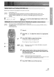
.... The jack most recently selected is established for each surround mode. • When both the DSP mode and Dolby Surroud mode are turned on VSX-D508) digital input connection is turned off the test tone. 21 FL CT FR 1 ,vim SW SL SR 1 4 MLEVEL±,, EI O ( .2„, tm TM... the same volume from each channel (Adjusting the speaker volume balance) memo • The sound pressure of each speaker when seated in Dolby (VSX-D508) or Dolby/DTS (VSX-D608) mode. memo • Initial setting is 0 dB. memo • Levels can be set the optical digital input 3 (DVD, ...
.... The jack most recently selected is established for each surround mode. • When both the DSP mode and Dolby Surroud mode are turned on VSX-D508) digital input connection is turned off the test tone. 21 FL CT FR 1 ,vim SW SL SR 1 4 MLEVEL±,, EI O ( .2„, tm TM... the same volume from each channel (Adjusting the speaker volume balance) memo • The sound pressure of each speaker when seated in Dolby (VSX-D508) or Dolby/DTS (VSX-D608) mode. memo • Initial setting is 0 dB. memo • Levels can be set the optical digital input 3 (DVD, ...
Owner's Manual
Page 25
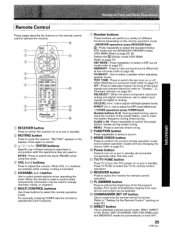
CD MUTING button Press to cancel. 0 A/v/ CHANNEL t""-if. Press again to mute the volume. CYO- - "MUTING" appears in standby. MULTI CONTROL moanI TV/SATI VCR' I rvmNnmL TUNER I vcrM' 12 00 DSP a Mga i l a TUC 6' aSgE ta cr) c:sM FUNCTION DIRECT FL DIMMER COMMANDER SETUP ) 13 14 "CWIE er RECEIVER button Press to switch the receiver on the remote control used to put in the display. Remote Control These pages describe the buttons on or to operate the receiver. 10 RECEIVER 0 (!) 1T 7. \ go CD i/ t" r>, F72 -= -
CD MUTING button Press to cancel. 0 A/v/ CHANNEL t""-if. Press again to mute the volume. CYO- - "MUTING" appears in standby. MULTI CONTROL moanI TV/SATI VCR' I rvmNnmL TUNER I vcrM' 12 00 DSP a Mga i l a TUC 6' aSgE ta cr) c:sM FUNCTION DIRECT FL DIMMER COMMANDER SETUP ) 13 14 "CWIE er RECEIVER button Press to switch the receiver on the remote control used to put in the display. Remote Control These pages describe the buttons on or to operate the receiver. 10 RECEIVER 0 (!) 1T 7. \ go CD i/ t" r>, F72 -= -
Owner's Manual
Page 27
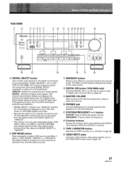
... for components not assigned to adjust the volume. a VIDEO INPUT jacks Connect a video camera, video game system, etc. O PHONES jack Connect headphones for private listening (the speakers turn off . First press DVD/LD, TV/SAT, MD/TAPE 1, CD or VCR 1 (VCR on VSX-D508) (Q, Function buttons) to select the component, then press SIGNAL SELECT...
... for components not assigned to adjust the volume. a VIDEO INPUT jacks Connect a video camera, video game system, etc. O PHONES jack Connect headphones for private listening (the speakers turn off . First press DVD/LD, TV/SAT, MD/TAPE 1, CD or VCR 1 (VCR on VSX-D508) (Q, Function buttons) to select the component, then press SIGNAL SELECT...
Owner's Manual
Page 29
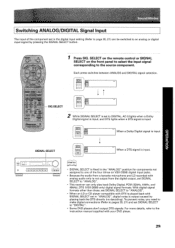
Each press switches between ANALOG and DIGITAL signal selection. SIG.SELECT Press SIG. SELECT on the remote control or SIGNAL SELECT on VSX-D508) digital input jacks. • Because the audio from the digital output, set SIGNAL SELECT to "ANALOG". • This receiver can be switched ...for components not assigned to one of the component set in "ANALOG", digital noise is input. To prevent noise, you need to make digital connections (Refer to pages 20, 21) and set SIGNAL SELECT to the source component. With digital signal formats other than these, set SIGNAL SELECT to...
Each press switches between ANALOG and DIGITAL signal selection. SIG.SELECT Press SIG. SELECT on the remote control or SIGNAL SELECT on VSX-D508) digital input jacks. • Because the audio from the digital output, set SIGNAL SELECT to "ANALOG". • This receiver can be switched ...for components not assigned to one of the component set in "ANALOG", digital noise is input. To prevent noise, you need to make digital connections (Refer to pages 20, 21) and set SIGNAL SELECT to the source component. With digital signal formats other than these, set SIGNAL SELECT to...


