
Owner's Manual
Page 2
...to the presence of uninsulated "dangerous voltage" within an equilateral triangle is used meets the required voltage (e.g., 230 V or 120 V) written on the rear panel. CAUTION: TO PREVENT THE RISK OF ELECTRIC SHOCK, DO NOT REMOVE COVER (OR BACK). The voltage of electric shock to which can cause severe ... the user to the presence of time. 14) Refer all servicing to improve heat radiation (at least 40 cm at top, 10 cm at rear, and 20 cm at plugs, convenience receptacles, and the point where they exit from overheating. Reorient or relocate the receiving antenna. - Consult the...
...to the presence of uninsulated "dangerous voltage" within an equilateral triangle is used meets the required voltage (e.g., 230 V or 120 V) written on the rear panel. CAUTION: TO PREVENT THE RISK OF ELECTRIC SHOCK, DO NOT REMOVE COVER (OR BACK). The voltage of electric shock to which can cause severe ... the user to the presence of time. 14) Refer all servicing to improve heat radiation (at least 40 cm at top, 10 cm at rear, and 20 cm at plugs, convenience receptacles, and the point where they exit from overheating. Reorient or relocate the receiving antenna. - Consult the...
Owner's Manual
Page 4
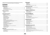
... a source...38 Playing an iPod...39 Playing a USB device...40 Listening to the radio...41 Bluetooth ADAPTER for buying this Pioneer product. Contents 01 Before you for Wireless Enjoyment of Music 42 06 Listening to your model properly. Thank you start Checking what......8 About using AVNavigator (included CD-ROM)...9 02 Controls and displays Remote control...11 Display...13 Front panel...14 03 Connecting your equipment Connecting your equipment...16 Rear panel...16 Determining the speakers' application...17 Placing the speakers...18 Connecting the speakers...19 Installing your speaker ...
... a source...38 Playing an iPod...39 Playing a USB device...40 Listening to the radio...41 Bluetooth ADAPTER for buying this Pioneer product. Contents 01 Before you for Wireless Enjoyment of Music 42 06 Listening to your model properly. Thank you start Checking what......8 About using AVNavigator (included CD-ROM)...9 02 Controls and displays Remote control...11 Display...13 Front panel...14 03 Connecting your equipment Connecting your equipment...16 Rear panel...16 Determining the speakers' application...17 Placing the speakers...18 Connecting the speakers...19 Installing your speaker ...
Owner's Manual
Page 15
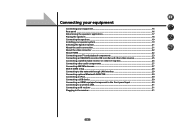
Connecting your equipment Connecting your equipment...16 Rear panel...16 Determining the speakers' application 17 Placing the speakers...18 Connecting the speakers...19 Installing your speaker system...19 Selecting the Speaker system...21 About ... through LAN interface 29 Connecting optional Bluetooth ADAPTER 30 Connecting an iPod...30 Connecting a USB device...30 Connecting an HDMI-equipped component to the front panel input 30 Connecting to a wireless LAN...31 Connecting an IR receiver...31 Plugging in the receiver...31 15
Connecting your equipment Connecting your equipment...16 Rear panel...16 Determining the speakers' application 17 Placing the speakers...18 Connecting the speakers...19 Installing your speaker system...19 Selecting the Speaker system...21 About ... through LAN interface 29 Connecting optional Bluetooth ADAPTER 30 Connecting an iPod...30 Connecting a USB device...30 Connecting an HDMI-equipped component to the front panel input 30 Connecting to a wireless LAN...31 Connecting an IR receiver...31 Plugging in the receiver...31 15
Owner's Manual
Page 16
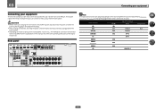
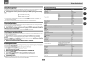
... IN 1 IN 2 Input Terminals Audio COAX-1 COAX-2 Component IN 1 DVR/BDR IN 3 OPT-2 TV OPT-1 HDMI 4 IN 4 HDMI 5 (front panel) IN 5 HDMI 6 IN 6 CD ANALOG-1 16 03 Connecting your equipment Connecting your home theater system. CAUTION ! Refer to change the assignments if other connections...to the operating instructions of the respective devices. This chapter explains the kinds of connection and terminal names may differ from the power outlets. ! Rear panel HDMI ASSIGNABLE 1-6 IR IN OUT IN 1 IN 2 IN 3 BD IN IN 4 IN 6 OUT LAN (10/100) OPTICAL ASSIGNABLE ...
... IN 1 IN 2 Input Terminals Audio COAX-1 COAX-2 Component IN 1 DVR/BDR IN 3 OPT-2 TV OPT-1 HDMI 4 IN 4 HDMI 5 (front panel) IN 5 HDMI 6 IN 6 CD ANALOG-1 16 03 Connecting your equipment Connecting your home theater system. CAUTION ! Refer to change the assignments if other connections...to the operating instructions of the respective devices. This chapter explains the kinds of connection and terminal names may differ from the power outlets. ! Rear panel HDMI ASSIGNABLE 1-6 IR IN OUT IN 1 IN 2 IN 3 BD IN IN 4 IN 6 OUT LAN (10/100) OPTICAL ASSIGNABLE ...
Owner's Manual
Page 31
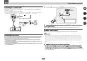
... your system instead of the remote sensor on the power cord or pinch the cord in the cord or tie it damaged, ask your nearest Pioneer authorized independent service company for IR compatibility. ! The HDMI indicator in after you find it with HDMI to the network is possible through a ...you keep your com- Refer to check for a replacement. ! ponent to the manual that came with HDMI function on the front panel. The power cords should be stepped on the rear of furniture, or other cables. A damaged power cord can cause a fire or give you can use the IR terminology. Check ...
... your system instead of the remote sensor on the power cord or pinch the cord in the cord or tie it damaged, ask your nearest Pioneer authorized independent service company for IR compatibility. ! The HDMI indicator in after you find it with HDMI to the network is possible through a ...you keep your com- Refer to check for a replacement. ! ponent to the manual that came with HDMI function on the front panel. The power cords should be stepped on the rear of furniture, or other cables. A damaged power cord can cause a fire or give you can use the IR terminology. Check ...
Owner's Manual
Page 35
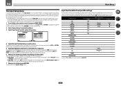
... HDMI Input Terminals Audio Component BD (BD) DVD SAT/CBL DVR/BDR IN 1 COAX-1 IN 1 IN 2 COAX-2 k IN 3 OPT-2 k HDMI 4 IN 4 HDMI 5 (front panel) IN 5 HDMI 6 IN 6 INTERNET RADIO SiriusXM PANDORA MEDIA SERVER FAVORITES iPod/USB TV CD TUNER OPT-1 ANALOG-1 ADAPTER PORT a Only the TV and CD inputs... can be still be assigned to the settings for easier identification. nected with the names on the rear panel (such as DVD or SAT/CBL which, in turn, correspond with an HDMI cable. The default names correspond with the names next to the...
... HDMI Input Terminals Audio Component BD (BD) DVD SAT/CBL DVR/BDR IN 1 COAX-1 IN 1 IN 2 COAX-2 k IN 3 OPT-2 k HDMI 4 IN 4 HDMI 5 (front panel) IN 5 HDMI 6 IN 6 INTERNET RADIO SiriusXM PANDORA MEDIA SERVER FAVORITES iPod/USB TV CD TUNER OPT-1 ANALOG-1 ADAPTER PORT a Only the TV and CD inputs... can be still be assigned to the settings for easier identification. nected with the names on the rear panel (such as DVD or SAT/CBL which, in turn, correspond with an HDMI cable. The default names correspond with the names next to the...
Owner's Manual
Page 63
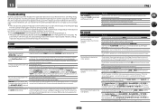
... settings for all the receiver's settings to the factory default settings. ! Note that the receiver has been reset to the factory default. The front panel display shows each of time so you 're finished, press STATUS again to turn the display off the display. The display shows RESET? HDMI HDMI... LFE Attenuate Auto delay Digital Safety Effect Level ExtendedStereo Other modes Default ON SB/FH Normal(SB/FH) SMALL SMALL SMALL SMALL SMALLx2 YES IN REAR 80 Hz OFF Brightest Amp OFF --- (OFF) --- (OFF) --- (AUTO) OFF LAST OFF FULL ON ON OFF 0.0 frame CH1 AUTO 0 dB 0 dB OFF OFF 90...
... settings for all the receiver's settings to the factory default settings. ! Note that the receiver has been reset to the factory default. The front panel display shows each of time so you 're finished, press STATUS again to turn the display off the display. The display shows RESET? HDMI HDMI... LFE Attenuate Auto delay Digital Safety Effect Level ExtendedStereo Other modes Default ON SB/FH Normal(SB/FH) SMALL SMALL SMALL SMALL SMALLx2 YES IN REAR 80 Hz OFF Brightest Amp OFF --- (OFF) --- (OFF) --- (AUTO) OFF LAST OFF FULL ON ON OFF 0.0 frame CH1 AUTO 0 dB 0 dB OFF OFF 90...
Owner's Manual
Page 86
...below. The ADVANCED MCACC blinks and the power does not turn on page 80). Unplug the receiver from the wall and call a Pioneer authorized independent service company. Check whether the cables used . No sound Symptom No sound is output when an input function is connected ...SIGNAL SEL). Check the channel level settings (see Switching the speaker terminals on page 58). If only one of speaker wire touching the rear panel or another component. Sometimes the trouble may be able to NO (see Connecting the speakers on page 80). Use TUNE i/j to select...
...below. The ADVANCED MCACC blinks and the power does not turn on page 80). Unplug the receiver from the wall and call a Pioneer authorized independent service company. Check whether the cables used . No sound Symptom No sound is output when an input function is connected ...SIGNAL SEL). Check the channel level settings (see Switching the speaker terminals on page 58). If only one of speaker wire touching the rear panel or another component. Sometimes the trouble may be able to NO (see Connecting the speakers on page 80). Use TUNE i/j to select...


