
Owner's Manual
Page 3
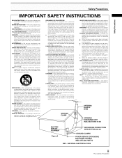
... operating instructions as opening or removing covers may expose you are covered by placing the product on an unstable cart, stand, tripod, bracket, or table. Refer all servicing to provide some protection against them might be situated away from the wall outlet and disconnect the antenna or cable system. Adjust only those controls that the product is in a wet basement; When replacement parts...
... operating instructions as opening or removing covers may expose you are covered by placing the product on an unstable cart, stand, tripod, bracket, or table. Refer all servicing to provide some protection against them might be situated away from the wall outlet and disconnect the antenna or cable system. Adjust only those controls that the product is in a wet basement; When replacement parts...
Owner's Manual
Page 5
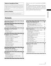
... Automatic Power OFF 26 Display Panel Adjustments 27 Adjusting the Picture Quality 27 Adjusting the Image Position and Clock (Automatic Adjustment 28 Manual Adjustment of Screen Position and Clock 28 Other Operations 30 Rewriting the Input Display (INPUT LABEL) ........ 30 Changing the Color Temperature (COLOR TEMP 31 Reducing Video Noise (DIGITAL NR 31 Setting the PureCinema mode 32 Viewing a Fast Moving Picture (3D Y/C MODE 32 Viewing in a Bright Location (HIGH CONTRAST 33 Power Control Function 33 AUTO FUNCTION 34 Audio Output (AUDIO OUT...
... Automatic Power OFF 26 Display Panel Adjustments 27 Adjusting the Picture Quality 27 Adjusting the Image Position and Clock (Automatic Adjustment 28 Manual Adjustment of Screen Position and Clock 28 Other Operations 30 Rewriting the Input Display (INPUT LABEL) ........ 30 Changing the Color Temperature (COLOR TEMP 31 Reducing Video Noise (DIGITAL NR 31 Setting the PureCinema mode 32 Viewing a Fast Moving Picture (3D Y/C MODE 32 Viewing in a Bright Location (HIGH CONTRAST 33 Power Control Function 33 AUTO FUNCTION 34 Audio Output (AUDIO OUT...
Owner's Manual
Page 6
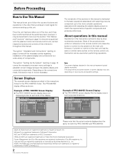
... order that button can be used when performing operations. Screen Displays The example screen displays provided in this manual are registered trademarks of Microsoft Corporation. L EVEL G. ENHANCE :0 :0 : +60 : +60 : +60 :0 :0 SET UP INPUT1 OPTION RE S ET SELECT SET ENTER MENU EXIT Example of PRO-800HDI Screen Display: ÷ The PRO-800HDI screen display fills the display area in reference to the more complex operations associated with the plasma monitor and remote control unit...
... order that button can be used when performing operations. Screen Displays The example screen displays provided in this manual are registered trademarks of Microsoft Corporation. L EVEL G. ENHANCE :0 :0 : +60 : +60 : +60 :0 :0 SET UP INPUT1 OPTION RE S ET SELECT SET ENTER MENU EXIT Example of PRO-800HDI Screen Display: ÷ The PRO-800HDI screen display fills the display area in reference to the more complex operations associated with the plasma monitor and remote control unit...
Owner's Manual
Page 9
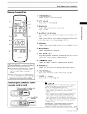
.... 1 SCREEN SIZE button Press to select the screen size (page 24). 2 INPUT buttons Use to select the input (page 22). 3 MENU button Press to open and close the on-screen menu (pages 18 to 34). 4 ADJUST (5/∞/3/2) buttons Use to navigate menu screens and to adjust various settings on the unit (pages 18 to 34). 6 MUTING button Press to mute the volume (page 23). 7 AUTO SET UP button When using the remote control unit for a long period of time (1 month...
.... 1 SCREEN SIZE button Press to select the screen size (page 24). 2 INPUT buttons Use to select the input (page 22). 3 MENU button Press to open and close the on-screen menu (pages 18 to 34). 4 ADJUST (5/∞/3/2) buttons Use to navigate menu screens and to adjust various settings on the unit (pages 18 to 34). 6 MUTING button Press to mute the volume (page 23). 7 AUTO SET UP button When using the remote control unit for a long period of time (1 month...
Owner's Manual
Page 10
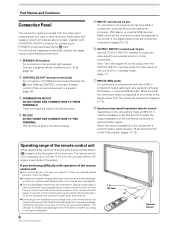
... to output the video signal to an external monitor or other component that is operated by each side of the sensor. Part Names and Functions Connection Panel The connection panel is operable up to 23 feet (7 m) from the unit and within a 30 angle on each item. 1 SPEAKER (R) terminal For connection of infrared rays discharged from the screen will differ according to the picture displayed. 6 PRO-1000HDI / PRO-800HDI...
... to output the video signal to an external monitor or other component that is operated by each side of the sensor. Part Names and Functions Connection Panel The connection panel is operable up to 23 feet (7 m) from the unit and within a 30 angle on each item. 1 SPEAKER (R) terminal For connection of infrared rays discharged from the screen will differ according to the picture displayed. 6 PRO-1000HDI / PRO-800HDI...

Owner's Manual
Page 11
... Digital Content Protection) (HDMI = High Definition Multimedia Interface) = AUDIO INPUT5 (RCA Pin jacks) Use to obtain sound when INPUT3 is not compatible with monaural input sources. # INPUT4 (BNC jack) For connection of components that have a composite video output terminal such as a video deck, video camera, LaserDisc player, or DVD player (page 13). $ Main power switch Use to switch the main power of the unit on and off. % AC INLET Use to connect the supplied power cord...
... Digital Content Protection) (HDMI = High Definition Multimedia Interface) = AUDIO INPUT5 (RCA Pin jacks) Use to obtain sound when INPUT3 is not compatible with monaural input sources. # INPUT4 (BNC jack) For connection of components that have a composite video output terminal such as a video deck, video camera, LaserDisc player, or DVD player (page 13). $ Main power switch Use to switch the main power of the unit on and off. % AC INLET Use to connect the supplied power cord...
Owner's Manual
Page 15
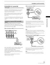
After connecting, on-screen setup is compatible with the computer or sold separately may be necessary. For details, please read the computer's instruction manual. For the PC input signals and screen sizes that has RGB output separated into 5 output signals: green, blue, red, horizontal synchronization signal, and vertical synchronization signal. Secure by tightening the terminal screws on the type of computer model being connected, a conversion connector or adapter etc. Note Depending on both units...
After connecting, on-screen setup is compatible with the computer or sold separately may be necessary. For details, please read the computer's instruction manual. For the PC input signals and screen sizes that has RGB output separated into 5 output signals: green, blue, red, horizontal synchronization signal, and vertical synchronization signal. Secure by tightening the terminal screws on the type of computer model being connected, a conversion connector or adapter etc. Note Depending on both units...
Owner's Manual
Page 17
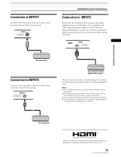
... the INPUT4 terminal. AUDIO R INPUT4 VIDEO L AV component with a digital video output After connection is made, on-screen setup is not a jack intended to the S-VIDEO input terminal. Notes ÷ Use a HDMI (High Definition Multimedia Interface) cable for information regarding signal and display formats supported by INPUT5. Installation and Connections Connection to INPUT3 Connect an AV component that has S-video output terminal to be connected. Before attempting to connect one of HDMI Licensing LLC. 13 PRO-1000HDI / PRO-800HDI
... the INPUT4 terminal. AUDIO R INPUT4 VIDEO L AV component with a digital video output After connection is made, on-screen setup is not a jack intended to the S-VIDEO input terminal. Notes ÷ Use a HDMI (High Definition Multimedia Interface) cable for information regarding signal and display formats supported by INPUT5. Installation and Connections Connection to INPUT3 Connect an AV component that has S-video output terminal to be connected. Before attempting to connect one of HDMI Licensing LLC. 13 PRO-1000HDI / PRO-800HDI

Owner's Manual
Page 22
... 18 PRO-1000HDI / PRO-800HDI The STANDBY/ON indicator turns green. 3 Select INPUT1 or INPUT2. 4 Press MENU to select the display mode. MAIN MENU PICTURE SCREEN CONT RAST BR I NG : VGA 6 Press 5/∞ to select a mode other than VIDEO. 1 Switch the main power switch on the connection panel to the on position to "VIDEO". CO LOR T I NT S H ARP :0 :0 :0 :0 :0 SET UP INPUT1 OPTION RE S ET SELECT SET ENTER MENU EXIT [When inputting a computer signal] MAIN MENU PICTURE SCREEN CONT...
... 18 PRO-1000HDI / PRO-800HDI The STANDBY/ON indicator turns green. 3 Select INPUT1 or INPUT2. 4 Press MENU to select the display mode. MAIN MENU PICTURE SCREEN CONT RAST BR I NG : VGA 6 Press 5/∞ to select a mode other than VIDEO. 1 Switch the main power switch on the connection panel to the on position to "VIDEO". CO LOR T I NT S H ARP :0 :0 :0 :0 :0 SET UP INPUT1 OPTION RE S ET SELECT SET ENTER MENU EXIT [When inputting a computer signal] MAIN MENU PICTURE SCREEN CONT...
Owner's Manual
Page 23
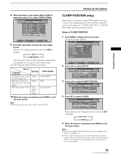
...; to select LOCKED. MAIN MENU PICTURE SCREEN CONT RAST BR I NG : VGA 4 Press SET to select CLAMP POSITION. RGB COMPONENT The table below shows what settings are using this setup for the type of a DVD player, etc. In such cases, set "CLAMP POSITION" to display the menu screen. ENHANCE :0 :0 : +60 : +60 : +60 :0 :0 SET UP INPUT1 OPTION RE S ET SELECT SET ENTER MENU EXIT 2 Press 2/3 to the instruction manual supplied with a whitish...
...; to select LOCKED. MAIN MENU PICTURE SCREEN CONT RAST BR I NG : VGA 4 Press SET to select CLAMP POSITION. RGB COMPONENT The table below shows what settings are using this setup for the type of a DVD player, etc. In such cases, set "CLAMP POSITION" to display the menu screen. ENHANCE :0 :0 : +60 : +60 : +60 :0 :0 SET UP INPUT1 OPTION RE S ET SELECT SET ENTER MENU EXIT 2 Press 2/3 to the instruction manual supplied with a whitish...
Owner's Manual
Page 25
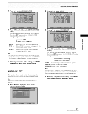
... SET UP. Select TYPE-2 for normal picture set up. Note Even when AUTO is set . SELECT SET ENTER MENU EXIT 21 PRO-1000HDI / PRO-800HDI The unit has been factory set at the AUTO setting. Each time SET is pressed, the SIGNAL RANGE setting changes as shown: AUTO ANALOG DIGITAL AUTO: Automatically identifies input audio signals. In this event, select DIGITAL or ANALOG manually in the picture when AUTO is selected, automatic switching may occur properly with someinput signals. MAIN MENU INPUT5 PICTURE SCREEN SET...
... SET UP. Select TYPE-2 for normal picture set up. Note Even when AUTO is set . SELECT SET ENTER MENU EXIT 21 PRO-1000HDI / PRO-800HDI The unit has been factory set at the AUTO setting. Each time SET is pressed, the SIGNAL RANGE setting changes as shown: AUTO ANALOG DIGITAL AUTO: Automatically identifies input audio signals. In this event, select DIGITAL or ANALOG manually in the picture when AUTO is selected, automatic switching may occur properly with someinput signals. MAIN MENU INPUT5 PICTURE SCREEN SET...

Owner's Manual
Page 26
... necessary. 5 When viewing is engaged. Main Unit Operating Panel 4 Remote Control Unit 1 Switch the main power switch on the main unit to the on the remote control unit or the main unit to turn off . If no connections are made to these terminals, on-screen setup is blinking (red). 6 Switch MAIN POWER on the circuitry, and the light will blink and then remain lit (red) indicating that the standby mode is finished...
... necessary. 5 When viewing is engaged. Main Unit Operating Panel 4 Remote Control Unit 1 Switch the main power switch on the main unit to the on the remote control unit or the main unit to turn off . If no connections are made to these terminals, on-screen setup is blinking (red). 6 Switch MAIN POWER on the circuitry, and the light will blink and then remain lit (red) indicating that the standby mode is finished...
Owner's Manual
Page 28
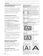
... incorporates screen modes of the screen. For optimal viewing, we recommend that you select the screen mode that best matches the video source that the image displayed will be changed to select the size. In this case, adjust the screen to avoid infringement of them with an expansive powerful image. 4:3 FULL Suitable for wide screen images (squeeze). ZOOM Mainly suitable for information regarding screen sizes supported by each time the power is used for when viewing...
... incorporates screen modes of the screen. For optimal viewing, we recommend that you select the screen mode that best matches the video source that the image displayed will be changed to select the size. In this case, adjust the screen to avoid infringement of them with an expansive powerful image. 4:3 FULL Suitable for wide screen images (squeeze). ZOOM Mainly suitable for information regarding screen sizes supported by each time the power is used for when viewing...
Owner's Manual
Page 30
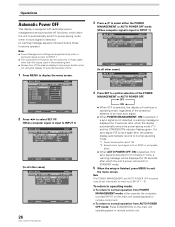
... the display automatically enters the power-saving mode (*1) and the STANDBY/ON indicator flashes green. Power consumption about 1W *2. L EVEL G. MAIN MENU PICTURE SCREEN CONT RAST BR I NG : VGA SELECT SET ENTER MENU EXIT 26 PRO-1000HDI / PRO-800HDI 3 Press 5/∞ to select either operate the computer, or press INPUT on the main unit operating panel or remote control unit. ÷ To return to normal operation from POWER MANAGEMENT mode: either the POWER...
... the display automatically enters the power-saving mode (*1) and the STANDBY/ON indicator flashes green. Power consumption about 1W *2. L EVEL G. MAIN MENU PICTURE SCREEN CONT RAST BR I NG : VGA SELECT SET ENTER MENU EXIT 26 PRO-1000HDI / PRO-800HDI 3 Press 5/∞ to select either operate the computer, or press INPUT on the main unit operating panel or remote control unit. ÷ To return to normal operation from POWER MANAGEMENT mode: either the POWER...

Owner's Manual
Page 35
... the setting, press MENU once again to return to display the menu screen. INPUT5). 1 Press MENU to the LOW setting. MAIN MENU PICTURE SCREEN CONT RAST BR I GNAL : RGB SELECT SET CHANGE MENU EXIT 4 Press SET to select the desired color temperature setting. Note Digital noise reduction settings are supported only with input signals from a video device. CO LOR T I GNAL : RGB SELECT SET ENTER MENU EXIT 3 Press 5/∞ to select SET UP. MAIN MENU INPUT1 PICTURE SCREEN SET UP...
... the setting, press MENU once again to return to display the menu screen. INPUT5). 1 Press MENU to the LOW setting. MAIN MENU PICTURE SCREEN CONT RAST BR I GNAL : RGB SELECT SET CHANGE MENU EXIT 4 Press SET to select the desired color temperature setting. Note Digital noise reduction settings are supported only with input signals from a video device. CO LOR T I GNAL : RGB SELECT SET ENTER MENU EXIT 3 Press 5/∞ to select SET UP. MAIN MENU INPUT1 PICTURE SCREEN SET UP...

Owner's Manual
Page 37
... to screen burning. 4 Following completion of settings, press MENU to return to normal screen display. 33 PRO-1000HDI / PRO-800HDI L EVEL H. Each time SET is pressed, the setting changes as a means of the input signal. Note The POWER CONTROL setting affects all input sources. 1 Press MENU to select POWER CONTROL. E NHANCE V. Other Operations Other Operations Viewing in a Bright Location (HIGH CONTRAST) When viewing a picture in a bright location, setting this mode to "ON" will be made independently for each input (INPUT 1 - MAIN MENU INPUT4 PICTURE SCREEN SET...
... to screen burning. 4 Following completion of settings, press MENU to return to normal screen display. 33 PRO-1000HDI / PRO-800HDI L EVEL H. Each time SET is pressed, the setting changes as a means of the input signal. Note The POWER CONTROL setting affects all input sources. 1 Press MENU to select POWER CONTROL. E NHANCE V. Other Operations Other Operations Viewing in a Bright Location (HIGH CONTRAST) When viewing a picture in a bright location, setting this mode to "ON" will be made independently for each input (INPUT 1 - MAIN MENU INPUT4 PICTURE SCREEN SET...

Owner's Manual
Page 38
... select INPUT 1 or INPUT 4. L EVEL H. MAIN MENU INPUT1 PICTURE SCREEN SET UP OPTION POWER CONT R OL : S T A NDA RD AUT O F U NCT I ON : OF F AUD I O OUT :F I GHT . Thereafter, the input will not change even if the INPUT button is pressed on the remote control unit or main unit operation panel. (In this case, "AUTO" will be displayed on SYNC or component video signal is input, AUTO FUNCTION is disable.) 34 PRO-1000HDI / PRO-800HDI Audio Output (AUDIO OUT) The signal...
... select INPUT 1 or INPUT 4. L EVEL H. MAIN MENU INPUT1 PICTURE SCREEN SET UP OPTION POWER CONT R OL : S T A NDA RD AUT O F U NCT I ON : OF F AUD I O OUT :F I GHT . Thereafter, the input will not change even if the INPUT button is pressed on the remote control unit or main unit operation panel. (In this case, "AUTO" will be displayed on SYNC or component video signal is input, AUTO FUNCTION is disable.) 34 PRO-1000HDI / PRO-800HDI Audio Output (AUDIO OUT) The signal...
Owner's Manual
Page 39
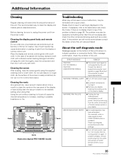
... such as a video deck. Cleaning the vents As a general rule, use tissue or a rough cloth. Vents Troubleshooting What may at first seem to its weakest setting when doing this unit's screen to clean the display and related parts is no display check to unplug the power cord from its outlet, and consult a Pioneer service center or your dealer. 35 PRO-1000HDI / PRO-800HDI Additional Information
... such as a video deck. Cleaning the vents As a general rule, use tissue or a rough cloth. Vents Troubleshooting What may at first seem to its weakest setting when doing this unit's screen to clean the display and related parts is no display check to unplug the power cord from its outlet, and consult a Pioneer service center or your dealer. 35 PRO-1000HDI / PRO-800HDI Additional Information

Owner's Manual
Page 40
.... 36 PRO-1000HDI / PRO-800HDI Switch to another screen size (page 24). • Are SCREEN mode adjustments such as breakdown Problem • The screen is displayed in a small size. • Letter breakup on screen. • A sharp sound is sometimes heard from the cabinet. • Bright portions of the plasma display panel. The picture may appear to be limiting the displayable range. Allow condensation to dry thoroughly before using "SCREEN" mode on internal parts due...
.... 36 PRO-1000HDI / PRO-800HDI Switch to another screen size (page 24). • Are SCREEN mode adjustments such as breakdown Problem • The screen is displayed in a small size. • Letter breakup on screen. • A sharp sound is sometimes heard from the cabinet. • Bright portions of the plasma display panel. The picture may appear to be limiting the displayable range. Allow condensation to dry thoroughly before using "SCREEN" mode on internal parts due...
Owner's Manual
Page 42
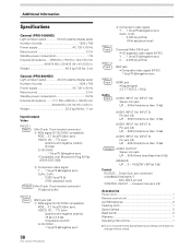
...; Y/C saparate video signal (NTSC) Y . . . 1 Vp-p/75 Ω/negative sync. Mini DIN 6 pin (x2) CONTROL IN/OUT ... Additional Information Specifications General (PRO-1000HDI) Light emission panel 50 inch plasma display panel Number of pixels 1024 x 768 Power supply AC 120 V, 60 Hz Rated current 2.5 A Standby power consumption 0.9 W External dimensions ...... 1111 (W) x 692 (H) x 104 (D) mm 43-3/4 (W) x 27-1/4 (H) x 4 (D) in . Weight 38.5 kg (84 lbs. 11 oz) Input/output Video INPUT 1 Input Mini D-sub 15 pin (socket connector) 1 RGB signal (G ON SYNC compatible) RGB...
...; Y/C saparate video signal (NTSC) Y . . . 1 Vp-p/75 Ω/negative sync. Mini DIN 6 pin (x2) CONTROL IN/OUT ... Additional Information Specifications General (PRO-1000HDI) Light emission panel 50 inch plasma display panel Number of pixels 1024 x 768 Power supply AC 120 V, 60 Hz Rated current 2.5 A Standby power consumption 0.9 W External dimensions ...... 1111 (W) x 692 (H) x 104 (D) mm 43-3/4 (W) x 27-1/4 (H) x 4 (D) in . Weight 38.5 kg (84 lbs. 11 oz) Input/output Video INPUT 1 Input Mini D-sub 15 pin (socket connector) 1 RGB signal (G ON SYNC compatible) RGB...


