Owner's Manual
Page 2
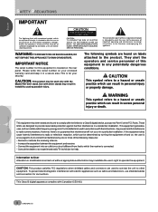
... the equipment and receiver. - NO USER-SERVICEABLE PARTS INSIDE. CAUTION This symbol refers to a hazard or unsafe practice which can result in a residential installation. If this serial number on labels attached to the product. Information to User Alteration or modifications carried out without appropriate authorization may invalidate the user's right to other stands may be determined by turning the equipment off...
... the equipment and receiver. - NO USER-SERVICEABLE PARTS INSIDE. CAUTION This symbol refers to a hazard or unsafe practice which can result in a residential installation. If this serial number on labels attached to the product. Information to User Alteration or modifications carried out without appropriate authorization may invalidate the user's right to other stands may be determined by turning the equipment off...

Owner's Manual
Page 3
... defeat the safety purpose of power supply to an antenna discharge unit, size of grounding conductors, location of overhead power lines or other hazards. Power-supply cords should not be sure the antenna or cable system is equipped with regard to proper grounding of the mast and supporting structure, grounding of the lead-in the vicinity of antenna-discharge unit, connection to overturn. Article 810...
... defeat the safety purpose of power supply to an antenna discharge unit, size of grounding conductors, location of overhead power lines or other hazards. Power-supply cords should not be sure the antenna or cable system is equipped with regard to proper grounding of the mast and supporting structure, grounding of the lead-in the vicinity of antenna-discharge unit, connection to overturn. Article 810...
Owner's Manual
Page 4
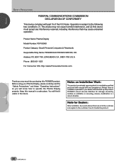
Product Name: Plasma Display Model Number: PDP-505HD Product Category: Class B Personal Computers & Peripherals Responsible Party Name: PIONEER ELECTRONICS SERVICE, INC. Notes on Installation Work: This product is marketed assuming that may cause undesired operation. Note for purchasing this PIONEER product. ENGLISH SAFETY PRECAUTIONS FEDERAL COMMUNICATIONS COMMISSION DECLARATION OF CONFORMITY This device complies with enough skill and competence. Keep this device must...
Product Name: Plasma Display Model Number: PDP-505HD Product Category: Class B Personal Computers & Peripherals Responsible Party Name: PIONEER ELECTRONICS SERVICE, INC. Notes on Installation Work: This product is marketed assuming that may cause undesired operation. Note for purchasing this PIONEER product. ENGLISH SAFETY PRECAUTIONS FEDERAL COMMUNICATIONS COMMISSION DECLARATION OF CONFORMITY This device complies with enough skill and competence. Keep this device must...

Owner's Manual
Page 5
... extremely thin 3-27/32 inches (9.8 cm) unit depth size opens up completely new possibilities to how viewing rooms may be designed. ÷ Unlimited placement possibilities Designed to be attached to a wall, set on a table top stand or placed on a floor rack, this unit can be installed many ways. ÷ Optional table top stand (sold separately) Stand designed specifically for PDP-505HD table top placement. (For...
... extremely thin 3-27/32 inches (9.8 cm) unit depth size opens up completely new possibilities to how viewing rooms may be designed. ÷ Unlimited placement possibilities Designed to be attached to a wall, set on a table top stand or placed on a floor rack, this unit can be installed many ways. ÷ Optional table top stand (sold separately) Stand designed specifically for PDP-505HD table top placement. (For...
Owner's Manual
Page 6
... supplied accessories 5 PART NAMES AND FUNCTIONS .......... 6 Main unit 6 Remote control unit 7 Connection panel 8 INSTALLATION AND CONNECTIONS .... 9 Installation of the unit 9 About the input jacks on this unit 10 Connection to INPUT1 10 Connection to INPUT2 10 Connection to INPUT3 and INPUT4 11 About DTV Set Top Box connection 14 Control cord connection 15 Power cord connection 15 How to route cables 16 SETTING UP THE SYSTEM 17 Setup after connection 17 OPERATIONS 20 Selecting an input source 20 Screen size...
... supplied accessories 5 PART NAMES AND FUNCTIONS .......... 6 Main unit 6 Remote control unit 7 Connection panel 8 INSTALLATION AND CONNECTIONS .... 9 Installation of the unit 9 About the input jacks on this unit 10 Connection to INPUT1 10 Connection to INPUT2 10 Connection to INPUT3 and INPUT4 11 About DTV Set Top Box connection 14 Control cord connection 15 Power cord connection 15 How to route cables 16 SETTING UP THE SYSTEM 17 Setup after connection 17 OPERATIONS 20 Selecting an input source 20 Screen size...
Owner's Manual
Page 7
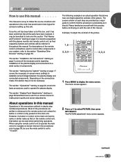
... by step numbered procedures. For descriptions of the picture. 1,6 2,3,5 CH VOL MUTING RECEIVER EDIT/ LEARN SOURCE POWER DVD TOP MENU MENU 1 8 TV/SAT/DTV/DVD MENU % SAT/DTV GUIDE SET/ SELECT % FAVORITES 7 3 VCR REC ¶ 4 (SAT)/DTV INFO ¡ ¢ 2,3,4 CU-PDP008 Î PLASMA DISPLAY REMOTE CONTROL UNIT 1 Press MENU to use the on page 39. The PICTURE adjustment menu screen appears. The section "Display Panel Adjustments" starting on -screen menus to make picture quality and screen adjustments. ○...
... by step numbered procedures. For descriptions of the picture. 1,6 2,3,5 CH VOL MUTING RECEIVER EDIT/ LEARN SOURCE POWER DVD TOP MENU MENU 1 8 TV/SAT/DTV/DVD MENU % SAT/DTV GUIDE SET/ SELECT % FAVORITES 7 3 VCR REC ¶ 4 (SAT)/DTV INFO ¡ ¢ 2,3,4 CU-PDP008 Î PLASMA DISPLAY REMOTE CONTROL UNIT 1 Press MENU to use the on page 39. The PICTURE adjustment menu screen appears. The section "Display Panel Adjustments" starting on -screen menus to make picture quality and screen adjustments. ○...
Owner's Manual
Page 11
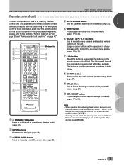
... used to operate other components, please refer to the sections "Remote code set up" on page 39 and "Remote control unit functions" on page 42". 1 2 3 4 5 6 TV CBL DTVDVD /VCR /SAT /LD STANDBY/ON INPUT 1 23 SCREEN MODE AUTO STILL 4 DISPLAY POWER AUDIO INPUT RECEIVER CC CLEAR DTV VIEW MODE 123 456 789 ¶ 0 CH ENTER CH RETURN CH VOL MUTING RECEIVER EDIT/ LEARN SOURCE POWER DVD TOP MENU MENU 1 8 % % TV/SAT/DTV/DVD MENU % SAT/DTV GUIDE SET...
... used to operate other components, please refer to the sections "Remote code set up" on page 39 and "Remote control unit functions" on page 42". 1 2 3 4 5 6 TV CBL DTVDVD /VCR /SAT /LD STANDBY/ON INPUT 1 23 SCREEN MODE AUTO STILL 4 DISPLAY POWER AUDIO INPUT RECEIVER CC CLEAR DTV VIEW MODE 123 456 789 ¶ 0 CH ENTER CH RETURN CH VOL MUTING RECEIVER EDIT/ LEARN SOURCE POWER DVD TOP MENU MENU 1 8 % % TV/SAT/DTV/DVD MENU % SAT/DTV GUIDE SET...
Owner's Manual
Page 13
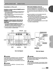
...) to 13/16 inch (20 mm) Side view diagram INSTALLATION AND CONNECTIONS ○ ○ ○ ○ ○ ○ CAUTION To avoid malfunction, overheating of deterioration and dirt build up on rear surface wall, etc.. PIONEER will not he held responsible for accident or damage caused by the use of parts and accessories manufactured by other than the PIONEER stand or installation bracket (sold separately...
...) to 13/16 inch (20 mm) Side view diagram INSTALLATION AND CONNECTIONS ○ ○ ○ ○ ○ ○ CAUTION To avoid malfunction, overheating of deterioration and dirt build up on rear surface wall, etc.. PIONEER will not he held responsible for accident or damage caused by the use of parts and accessories manufactured by other than the PIONEER stand or installation bracket (sold separately...

Owner's Manual
Page 16
..., G ON SYNC and composite SYNC are made, the picture may not be not displayed normally. ÷ When using the G ON SYNC connection (as shown left). ENGLISH INSTALLATION AND CONNECTIONS ○ Connection of G ON SYNC analog RGB source Make G ON SYNC connections for an AV component with output that has the synchronization signal layered on top of the green signal. Notes ÷ When making G ON SYNC connections, do not connect anything to...
..., G ON SYNC and composite SYNC are made, the picture may not be not displayed normally. ÷ When using the G ON SYNC connection (as shown left). ENGLISH INSTALLATION AND CONNECTIONS ○ Connection of G ON SYNC analog RGB source Make G ON SYNC connections for an AV component with output that has the synchronization signal layered on top of the green signal. Notes ÷ When making G ON SYNC connections, do not connect anything to...
Owner's Manual
Page 17
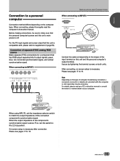
... PC input signals and screen sizes that has RGB output separated into 5 output signals: green, blue, red, horizontal synchronization signal, and vertical synchronization signal. INSTALLATION AND CONNECTIONS ○ ○ ○ ○ ○ ○ ○ ○ ○ ○ ○ ○ ○ ○ ○ When using INPUT3, set this unit and the personal computer's output terminal. When connecting, please thoroughly read your computer. Connection of computer model being connected, a conversion connector or adapter etc. After connecting...
... PC input signals and screen sizes that has RGB output separated into 5 output signals: green, blue, red, horizontal synchronization signal, and vertical synchronization signal. INSTALLATION AND CONNECTIONS ○ ○ ○ ○ ○ ○ ○ ○ ○ ○ ○ ○ ○ ○ ○ When using INPUT3, set this unit and the personal computer's output terminal. When connecting, please thoroughly read your computer. Connection of computer model being connected, a conversion connector or adapter etc. After connecting...
Owner's Manual
Page 21
... T USE: END: MENU ○ ○ STANDBY/ON INPUT MENU ADJUST SET S.MODE RETURN 2 2 3 4,10 5,6,7 8,9 4,10 5,6,7 8,9 TV CBL DTVDVD /VCR /SAT /LD STANDBY/ON INPUT 1 23 SCREEN MODE AUTO STILL 4 DISPLAY POWER AUDIO INPUT RECEIVER C C CLEAR DTV VIEW MODE 123 456 789 ¶ 0 CH ENTER CH RETURN CH VOL MUTING RECEIVER EDIT/ LEARN SOURCE POWER DVD TOP MENU MENU 1 8 % % TV/SAT/DTV/DVD MENU % SAT/DTV GUIDE SET/ SELECT % (SAT)/DTV INFO FAVORITES 7 3 VCR REC ¶ 4 ¡ ¢ 3 5,6,7 8,9 CU-PDP008 Î PLASMA DISPLAY REMOTE CONTROL...
... T USE: END: MENU ○ ○ STANDBY/ON INPUT MENU ADJUST SET S.MODE RETURN 2 2 3 4,10 5,6,7 8,9 4,10 5,6,7 8,9 TV CBL DTVDVD /VCR /SAT /LD STANDBY/ON INPUT 1 23 SCREEN MODE AUTO STILL 4 DISPLAY POWER AUDIO INPUT RECEIVER C C CLEAR DTV VIEW MODE 123 456 789 ¶ 0 CH ENTER CH RETURN CH VOL MUTING RECEIVER EDIT/ LEARN SOURCE POWER DVD TOP MENU MENU 1 8 % % TV/SAT/DTV/DVD MENU % SAT/DTV GUIDE SET/ SELECT % (SAT)/DTV INFO FAVORITES 7 3 VCR REC ¶ 4 ¡ ¢ 3 5,6,7 8,9 CU-PDP008 Î PLASMA DISPLAY REMOTE CONTROL...
Owner's Manual
Page 23
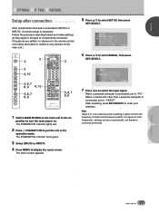
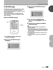
... LABEL EX I NPUT LABEL EXI T USE: END: MENU ○ ○ Setup of G ON SYNC connection 1,5 CH VOL MUTING RECEIVER EDIT/ LEARN SOURCE POWER DVD TOP MENU MENU 1 8 % % TV/SAT/DTV/DVD MENU % SAT/DTV GUIDE SET/ SELECT % FAVORITES 7 3 VCR REC ¶ 4 (SAT)/DTV INFO ¡ ¢ 2,3,4 CU-PDP008 Î PLASMA DISPLAY REMOTE CONTROL UNIT 1 Press MENU to close the menu screen. If the component being used is a model where G ON SYNC connection is necessary. ○ ○ ○...
... LABEL EX I NPUT LABEL EXI T USE: END: MENU ○ ○ Setup of G ON SYNC connection 1,5 CH VOL MUTING RECEIVER EDIT/ LEARN SOURCE POWER DVD TOP MENU MENU 1 8 % % TV/SAT/DTV/DVD MENU % SAT/DTV GUIDE SET/ SELECT % FAVORITES 7 3 VCR REC ¶ 4 (SAT)/DTV INFO ¡ ¢ 2,3,4 CU-PDP008 Î PLASMA DISPLAY REMOTE CONTROL UNIT 1 Press MENU to close the menu screen. If the component being used is a model where G ON SYNC connection is necessary. ○ ○ ○...
Owner's Manual
Page 25
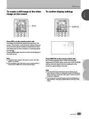
...; Normal display of the video input source is selected to view it (recipes in a cooking program for example). Notes ÷ The vertical and horizontal frequencies are displayed on the remote control unit. The image currently being viewed is displayed. ÷ The vertical and horizontal frequencies that would normally be slightly different from the actual values. The currently selected input, vertical and horizontal frequencies, PICTURE mode, screen size, AUTO SCREEN setting, and input signal format are displayed only...
...; Normal display of the video input source is selected to view it (recipes in a cooking program for example). Notes ÷ The vertical and horizontal frequencies are displayed on the remote control unit. The image currently being viewed is displayed. ÷ The vertical and horizontal frequencies that would normally be slightly different from the actual values. The currently selected input, vertical and horizontal frequencies, PICTURE mode, screen size, AUTO SCREEN setting, and input signal format are displayed only...
Owner's Manual
Page 32
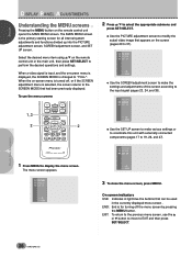
...; PLASMA DISPLAY REMOTE CONTROL UNIT 1 Press MENU to 37). PICTURE SCREEN SET UP . ○ ○ When a video signal is the primary starting screen for turning off , or if the SCREEN adjustment menu is turned off the menu screen by pressing the MENU button. The menu screen appears. ○ ○ ○ ○ ○ ○ ○ ○ ○ ○ PICTURE SCREEN SET UP . On screen indicators USE: Indicates in light blue the buttons that can be used in the currently displayed menu screen . The MAIN MENU screen is input...
...; PLASMA DISPLAY REMOTE CONTROL UNIT 1 Press MENU to 37). PICTURE SCREEN SET UP . ○ ○ When a video signal is the primary starting screen for turning off , or if the SCREEN adjustment menu is turned off the menu screen by pressing the MENU button. The menu screen appears. ○ ○ ○ ○ ○ ○ ○ ○ ○ ○ PICTURE SCREEN SET UP . On screen indicators USE: Indicates in light blue the buttons that can be used in the currently displayed menu screen . The MAIN MENU screen is input...
Owner's Manual
Page 34
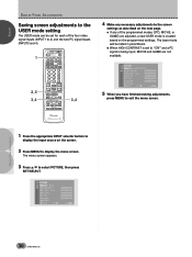
PICTURE MOD E : U S E R ( S T D ) CON T RA S T BLACK LVL . ENGLISH DISPLAY PANEL ADJUSTMENTS % % DISPLAY PANEL ADJUSTMENTS Saving screen adjustments to the USER mode setting The USER mode can be listed in parenthesis. ÷ When HIGH CONTRAST is set for each of the four video signal inputs (INPUT1 to 4) and the two PC signal inputs (INPUT3 and 4). 1 2,5 3,4 TV CBL DTVDVD /VCR /SAT /LD STANDBY/ON INPUT 1 23 SCREEN MODE AUTO STILL 4 DISPLAY POWER AUDIO INPUT RECEIVER CC CLEAR DTV VIEW MODE 123 456 789 ¶ 0 CH ENTER CH RETURN...
PICTURE MOD E : U S E R ( S T D ) CON T RA S T BLACK LVL . ENGLISH DISPLAY PANEL ADJUSTMENTS % % DISPLAY PANEL ADJUSTMENTS Saving screen adjustments to the USER mode setting The USER mode can be listed in parenthesis. ÷ When HIGH CONTRAST is set for each of the four video signal inputs (INPUT1 to 4) and the two PC signal inputs (INPUT3 and 4). 1 2,5 3,4 TV CBL DTVDVD /VCR /SAT /LD STANDBY/ON INPUT 1 23 SCREEN MODE AUTO STILL 4 DISPLAY POWER AUDIO INPUT RECEIVER CC CLEAR DTV VIEW MODE 123 456 789 ¶ 0 CH ENTER CH RETURN...

Owner's Manual
Page 35
.... Change from INPUT3 or INPUT4, the following screen is displayed. DISPLAY PANEL ADJUSTMENTS ○ ○ 31 En ENGLISH DISPLAY PANEL ADJUSTMENTS Adjusting the picture quality The PICTURE adjustment screen provides the adjustment items listed in the picture. The menu screen appears. 2 Press 5/∞ to INPUT4) and for each signal type (video or PC). COLOR T I NT SHARP OTHER EX I T USE: END: MENU When viewing an image from a personal computer from the center position is set to display the menu screen. Note...
.... Change from INPUT3 or INPUT4, the following screen is displayed. DISPLAY PANEL ADJUSTMENTS ○ ○ 31 En ENGLISH DISPLAY PANEL ADJUSTMENTS Adjusting the picture quality The PICTURE adjustment screen provides the adjustment items listed in the picture. The menu screen appears. 2 Press 5/∞ to INPUT4) and for each signal type (video or PC). COLOR T I NT SHARP OTHER EX I T USE: END: MENU When viewing an image from a personal computer from the center position is set to display the menu screen. Note...
Owner's Manual
Page 43
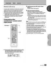
... supplied with the plasma display panel, remote control signals need to enter the number 24. ÷ If the LED indicator blinks rapidly when the number buttons are two methods of setting remote control signals. ÷ Programming the other manufacturers' remote control signal presets into this operation, press EDIT again. ÷ If the mode switch position is changed while in the usual manner. Programming other manufacturers' audio/video components using the LEARN mode of the other manufacturers' remote control signals directly from the table...
... supplied with the plasma display panel, remote control signals need to enter the number 24. ÷ If the LED indicator blinks rapidly when the number buttons are two methods of setting remote control signals. ÷ Programming the other manufacturers' remote control signal presets into this operation, press EDIT again. ÷ If the mode switch position is changed while in the usual manner. Programming other manufacturers' audio/video components using the LEARN mode of the other manufacturers' remote control signals directly from the table...
Owner's Manual
Page 45
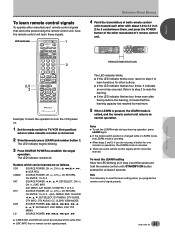
... can be learned are some remote control signals which cannot be learned. LED indicator 2,5 3 TV CBL DTVDVD /VCR /SAT /LD STANDBY/ON INPUT 1 23 SCREEN MODE AUTO STILL 4 DISPLAY POWER AUDIO INPUT RECEIVER C C CLEAR DTV VIEW MODE 123 456 789 ¶ 0 CH ENTER CH RETURN CH VOL MUTING RECEIVER EDIT/ LEARN SOURCE POWER DVD TOP MENU MENU 1 8 % % TV/SAT/DTV/DVD MENU % SAT/DTV GUIDE SET/ SELECT % FAVORITES 7 3 VCR REC ¶ 4 (SAT) /DTV INFO ¡ ¢...
... can be learned are some remote control signals which cannot be learned. LED indicator 2,5 3 TV CBL DTVDVD /VCR /SAT /LD STANDBY/ON INPUT 1 23 SCREEN MODE AUTO STILL 4 DISPLAY POWER AUDIO INPUT RECEIVER C C CLEAR DTV VIEW MODE 123 456 789 ¶ 0 CH ENTER CH RETURN CH VOL MUTING RECEIVER EDIT/ LEARN SOURCE POWER DVD TOP MENU MENU 1 8 % % TV/SAT/DTV/DVD MENU % SAT/DTV GUIDE SET/ SELECT % FAVORITES 7 3 VCR REC ¶ 4 (SAT) /DTV INFO ¡ ¢...

Owner's Manual
Page 55
...) ○ ○ ÷ Has setup been done correctly after first turning the main power on/off, or unplugging the power cord and ○ ○ re-plugging it of dust buildup (set to "MODE1" or "MODE2"? (page 2 6) ○ ÷ Is connection to other components being used such as picture size made correctly? (page 38). ○ ÷ Adjust the picture tone (page 31). ○ ○...
...) ○ ○ ÷ Has setup been done correctly after first turning the main power on/off, or unplugging the power cord and ○ ○ re-plugging it of dust buildup (set to "MODE1" or "MODE2"? (page 2 6) ○ ÷ Is connection to other components being used such as picture size made correctly? (page 38). ○ ÷ Adjust the picture tone (page 31). ○ ○...

Owner's Manual
Page 56
... strain. In this case, unplug the power cord from the power outlet and request repair from your nearest sales outlet. ÷ The plasma display panel of internal parts etc.. ENGLISH ADDITIONAL INFORMATION ○ ○ Problems commonly mistaken as breakdown ○ ○ ○ Problem ÷ The screen is displayed in a small size. ÷ Letter breakup on screen. ÷ A sharp sound is sometimes heard from the cabinet. ÷...
... strain. In this case, unplug the power cord from the power outlet and request repair from your nearest sales outlet. ÷ The plasma display panel of internal parts etc.. ENGLISH ADDITIONAL INFORMATION ○ ○ Problems commonly mistaken as breakdown ○ ○ ○ Problem ÷ The screen is displayed in a small size. ÷ Letter breakup on screen. ÷ A sharp sound is sometimes heard from the cabinet. ÷...


