
Technical Manual
Page 1
...read instructions indicated by experienced, qualified experts. Before installation and preparatory work to qualified personnel, or consult the nearest PIONEER dealer for assistance. ÷ We accept no responsibility for losses resulting from the use of parts other than those... for accident or loss resulting from natural disasters. TECHNICAL MANUAL (Ver. 1.0) HANDWRITING DEVICE: PDK-50HW3 Supported plasma displays: PDP-504CMX PDP-503CMX PDP-50MXE1 PDP-50MXE1-S PDP-503MXE This manual provides precautions and information for those supplied by us. • We guarantee the performance of...
...read instructions indicated by experienced, qualified experts. Before installation and preparatory work to qualified personnel, or consult the nearest PIONEER dealer for assistance. ÷ We accept no responsibility for losses resulting from the use of parts other than those... for accident or loss resulting from natural disasters. TECHNICAL MANUAL (Ver. 1.0) HANDWRITING DEVICE: PDK-50HW3 Supported plasma displays: PDP-504CMX PDP-503CMX PDP-50MXE1 PDP-50MXE1-S PDP-503MXE This manual provides precautions and information for those supplied by us. • We guarantee the performance of...
Technical Manual
Page 3
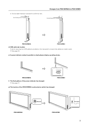
... (excluding screw heads) ] PDK-50HW2A PDK-50HW3 d) USB cable clip location A clip for securing two USB cables is provided on the rear panel to check plasma display operating status. ] PDK-50HW2A f) The flash pattern of the PEN-NORMAL mode selector switch has changed . ] See page 21. 2.
... (excluding screw heads) ] PDK-50HW2A PDK-50HW3 d) USB cable clip location A clip for securing two USB cables is provided on the rear panel to check plasma display operating status. ] PDK-50HW2A f) The flash pattern of the PEN-NORMAL mode selector switch has changed . ] See page 21. 2.
Technical Manual
Page 6
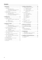
...2.2.3 Installation precautions 14 3. Contents 1. Maintenance and Cleaning 40 6. Installation Procedures 15 3.1 Unpacking 15 3.1.1 Plasma display monitor (PDP-504CMX/PDP-50MXE1/PDP-50MXE1-S) ... 15 3.1.2 Handwriting device (PDK-50HW3 16 3.2 Assembly and Connections 17 3.2.1 Installing the handwriting... 38 5. Q & A 43 7.1 Hardware-Related Q&A 43 7.2 Driver Software-Related Q&A 45 8. Troubleshooting 47 8.1 Plasma Display (PDP-504CMX/PDP-50MXE1/PDP-50MXE1-S 47 8.2 Handwriting Device (PDK-50HW3 49 9. Installation Site 12 2.1 Installation Site 12 2.2 Installation Conditions 12...
...2.2.3 Installation precautions 14 3. Contents 1. Maintenance and Cleaning 40 6. Installation Procedures 15 3.1 Unpacking 15 3.1.1 Plasma display monitor (PDP-504CMX/PDP-50MXE1/PDP-50MXE1-S) ... 15 3.1.2 Handwriting device (PDK-50HW3 16 3.2 Assembly and Connections 17 3.2.1 Installing the handwriting... 38 5. Q & A 43 7.1 Hardware-Related Q&A 43 7.2 Driver Software-Related Q&A 45 8. Troubleshooting 47 8.1 Plasma Display (PDP-504CMX/PDP-50MXE1/PDP-50MXE1-S 47 8.2 Handwriting Device (PDK-50HW3 49 9. Installation Site 12 2.1 Installation Site 12 2.2 Installation Conditions 12...
Technical Manual
Page 7
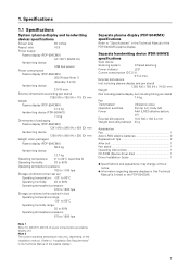
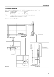
...% Operating atmospheric pressure: 670 to 1500 hpa Separate plasma display (PDP-504CMX) specifications Refer to the PDP-504CMX. External dimensions (excluding pen stand) 1258 (W) x 758 (H) x 115 (D) mm Weight Plasma display (PDP-504CMX) 41.0 kg Handwriting device (PDK-50HW3) 7.4 kg Dimensions of the PDP-504CMX plasma display. Note 1 Allow for 400 W 400 VA of the plasma display.) 7 Note 2 The correct operating temperature may...
...% Operating atmospheric pressure: 670 to 1500 hpa Separate plasma display (PDP-504CMX) specifications Refer to the PDP-504CMX. External dimensions (excluding pen stand) 1258 (W) x 758 (H) x 115 (D) mm Weight Plasma display (PDP-504CMX) 41.0 kg Handwriting device (PDK-50HW3) 7.4 kg Dimensions of the PDP-504CMX plasma display. Note 1 Allow for 400 W 400 VA of the plasma display.) 7 Note 2 The correct operating temperature may...
Technical Manual
Page 8
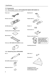
Specifications 1.2 Accessories 1.2.1 Plasma display monitor (PDP-504CMX/PDP-50MXE1/PDP-50MXE1-S) Check that the following accessories were supplied. Power cord Bead band x 2 Remote control unit Display stand x 2 AA (R6) batteries x 2 Cleaning cloth (for wiping front panel) Washer x 2 Hex hole bolt x 2 Speed clamp x 2 Ferrite core (PDP-50MXE1/PDP-50MXE1-S only) Remote control unit case x 1 Use as a holder for the...
Specifications 1.2 Accessories 1.2.1 Plasma display monitor (PDP-504CMX/PDP-50MXE1/PDP-50MXE1-S) Check that the following accessories were supplied. Power cord Bead band x 2 Remote control unit Display stand x 2 AA (R6) batteries x 2 Cleaning cloth (for wiping front panel) Washer x 2 Hex hole bolt x 2 Speed clamp x 2 Ferrite core (PDP-50MXE1/PDP-50MXE1-S only) Remote control unit case x 1 Use as a holder for the...
Technical Manual
Page 9
...: 48.4 kg (plasma display (PDP-504CMX) 41.0 kg plus handwriting device 7.4 kg) Materials: Front panel (frame Aluminum Corner sections Resin Base shield, corner reinforcement .... 1. Metal plate Finish: Front panel (frame Painting (Pioneer original color) Base shield, corner reinforcement .... Plating 1258 115 92 82 74 (excluding screw heads and plasma display) 758 56 Plasma display indicator Remote...
...: 48.4 kg (plasma display (PDP-504CMX) 41.0 kg plus handwriting device 7.4 kg) Materials: Front panel (frame Aluminum Corner sections Resin Base shield, corner reinforcement .... 1. Metal plate Finish: Front panel (frame Painting (Pioneer original color) Base shield, corner reinforcement .... Plating 1258 115 92 82 74 (excluding screw heads and plasma display) 758 56 Plasma display indicator Remote...
Technical Manual
Page 10
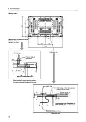
Specifications 278 758 344 PEN NORMAL PEN-NORMAL mode selector switch (in lower left corner as seen from rear) 4 20 PPEN NNORMAL Plasma display side panel 9 6 33 278 278 1258 USB cable exit 22 3 22 66 14 PEN-NORMAL mode selector switch (in lower left corner as seen from rear) 17 5 2 6 Cable clip 11 USB cable, 5 mm in diameter (approx. 1.4 m long) Bottom panel of plasma display R4 9 Dimensions from right edge of 115 14 PDK-50HW3 as seen from rear PDK-50HW3 center line USB cable exit 10 1.
Specifications 278 758 344 PEN NORMAL PEN-NORMAL mode selector switch (in lower left corner as seen from rear) 4 20 PPEN NNORMAL Plasma display side panel 9 6 33 278 278 1258 USB cable exit 22 3 22 66 14 PEN-NORMAL mode selector switch (in lower left corner as seen from rear) 17 5 2 6 Cable clip 11 USB cable, 5 mm in diameter (approx. 1.4 m long) Bottom panel of plasma display R4 9 Dimensions from right edge of 115 14 PDK-50HW3 as seen from rear PDK-50HW3 center line USB cable exit 10 1.
Technical Manual
Page 11
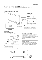
1. Specifications 1.4 Name and Function of Parts & Pin Layout 1.4.1 Plasma display monitor (PDP-504CMX/PDP-50MXE1/PDP-50MXE1-S) For information on the plasma display, refer to "Name and Function of Parts" in accordance with whether you will produce lower screen definition, however, compared to write on the screen. ...
1. Specifications 1.4 Name and Function of Parts & Pin Layout 1.4.1 Plasma display monitor (PDP-504CMX/PDP-50MXE1/PDP-50MXE1-S) For information on the plasma display, refer to "Name and Function of Parts" in accordance with whether you will produce lower screen definition, however, compared to write on the screen. ...
Technical Manual
Page 12
... but not recommended since the table top may not be sturdy enough to "Installation Conditions" in the Technical Manual of the plasma display. 2.2.1 List showing compatibility of standard metal fittings Model No. Installation Site 2.1 Installation Site The installation site precautions for...CART SPEAKER SYSTEM Compatible Requirements Not possible since the table top may not be in the Technical Manual of the PDP-504CMX/PDP50MXE1/PDP-50MXE1-S. 2.2 Installation Conditions For information on calculation of heat generation and heat dissipation, installation site and installation on...
... but not recommended since the table top may not be sturdy enough to "Installation Conditions" in the Technical Manual of the plasma display. 2.2.1 List showing compatibility of standard metal fittings Model No. Installation Site 2.1 Installation Site The installation site precautions for...CART SPEAKER SYSTEM Compatible Requirements Not possible since the table top may not be in the Technical Manual of the PDP-504CMX/PDP50MXE1/PDP-50MXE1-S. 2.2 Installation Conditions For information on calculation of heat generation and heat dissipation, installation site and installation on...

Technical Manual
Page 13
... position. 2. Refer to take their prevention in the detailed setting mode of the driver cannot be tilted in this case, the position of the plasma display. ¶ Calculate the distance between horizontal, upward-facing position and the 25° downward- If you install a guard, however, you ... Manual of the pen tip and that the calibration in consideration when installing the handwriting device horizontally. 13 Always take ventilation of the plasma display monitor in consideration. ¶ When the handwriting device is tilted, the user should watch the screen obliquely and, in the ...
... position. 2. Refer to take their prevention in the detailed setting mode of the driver cannot be tilted in this case, the position of the plasma display. ¶ Calculate the distance between horizontal, upward-facing position and the 25° downward- If you install a guard, however, you ... Manual of the pen tip and that the calibration in consideration when installing the handwriting device horizontally. 13 Always take ventilation of the plasma display monitor in consideration. ¶ When the handwriting device is tilted, the user should watch the screen obliquely and, in the ...

Technical Manual
Page 14
... but may be checked in NORMAL mode. In this case, it is usually normal but may sometimes be checked in such a location will make the plasma display difficult to use the systems in individual installations. 14 When the system malfunctions due to the presence of infrared radiation. Also, when equipment generating...
... but may be checked in NORMAL mode. In this case, it is usually normal but may sometimes be checked in such a location will make the plasma display difficult to use the systems in individual installations. 14 When the system malfunctions due to the presence of infrared radiation. Also, when equipment generating...
Technical Manual
Page 15
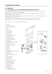
... Pad 4. Power cord case 7. Cable tie 19. Polyethylene bag for catalog 27. Bag for warranty card 25. Plasma caution sheet 30. Plasma caution sheet 32. Precautions sheet 34. Description 1. Conversion plug for screen) 17. Display stand 15. Ground connection ...x 2, bead band x 2) 16. Wiping cloth (for Japan 10. 3. Installation Procedures 3.1 Unpacking 3.1.1 Plasma display monitor (PDP-504CMX/PDP-50MXE1/PDP-50MXE1-S) ¶ Any transportation of the carton. ¶ Plasma display monitor is mode off grass. This warning is also indicated on the upper face of the carton....
... Pad 4. Power cord case 7. Cable tie 19. Polyethylene bag for catalog 27. Bag for warranty card 25. Plasma caution sheet 30. Plasma caution sheet 32. Precautions sheet 34. Description 1. Conversion plug for screen) 17. Display stand 15. Ground connection ...x 2, bead band x 2) 16. Wiping cloth (for Japan 10. 3. Installation Procedures 3.1 Unpacking 3.1.1 Plasma display monitor (PDP-504CMX/PDP-50MXE1/PDP-50MXE1-S) ¶ Any transportation of the carton. ¶ Plasma display monitor is mode off grass. This warning is also indicated on the upper face of the carton....

Technical Manual
Page 17
... 2. 3.2 Assembly and Connections 3.2.1 Installing the handwriting device (PDK-50HW3) 3. Installation Procedures Notes: ¶ Always install the plasma display on a mobile cart before installing scan device. ¶ After installing scan device, never attempt to lift the plasma display to install on a mobile cart. ¶ If the need arises to move scan device after...
... 2. 3.2 Assembly and Connections 3.2.1 Installing the handwriting device (PDK-50HW3) 3. Installation Procedures Notes: ¶ Always install the plasma display on a mobile cart before installing scan device. ¶ After installing scan device, never attempt to lift the plasma display to install on a mobile cart. ¶ If the need arises to move scan device after...

Technical Manual
Page 19
... . 5. Note: Turn the power off before making or changing connections. 3.3 Computer Setup Example Setup procedure differs with the plasma display. Make sure that the "Maze" and "OpenGL" screen savers are not in use. 4. Disable sleep, standby and all...Visual effects"= "Display icons in the Operating Instructions supplied with computer type. http://windowsupdate.microsoft.com/ 19 Selection of plasma display input is adjusted depending on connecting the plasma display to a computer, refer to "Installation and Connections" in full color" check box. 3. 3. Installation Procedures ...
... . 5. Note: Turn the power off before making or changing connections. 3.3 Computer Setup Example Setup procedure differs with the plasma display. Make sure that the "Maze" and "OpenGL" screen savers are not in use. 4. Disable sleep, standby and all...Visual effects"= "Display icons in the Operating Instructions supplied with computer type. http://windowsupdate.microsoft.com/ 19 Selection of plasma display input is adjusted depending on connecting the plasma display to a computer, refer to "Installation and Connections" in full color" check box. 3. 3. Installation Procedures ...
Technical Manual
Page 20
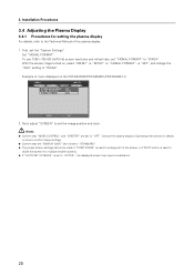
Installation Procedures 3.4 Adjusting the Plasma Display 3.4.1 Procedures for details on , select "MENU" = "SETUP" = "SIGNAL FORMAT" = "SET", and change the "XGA" setting to set the image position and clock. Notes: ¶ ... the screen into multiple smaller screens. ¶ If "AUTO SET UP MODE" is set "SIGNAL FORMAT" to the Technical Manual of menu displayed on the PDP-504CMX/PDP-50MXE1/PDP-50MXE1-S MENU INPUT1 PICTURE SCREEN SETUP OPTION POWER MANAGEMENT CLAMP POSITION SIGNAL FORMAT : OFF : AUTO : XGA SET ENTER MENU EXIT 2. To use 1280 x 768...
Installation Procedures 3.4 Adjusting the Plasma Display 3.4.1 Procedures for details on , select "MENU" = "SETUP" = "SIGNAL FORMAT" = "SET", and change the "XGA" setting to set the image position and clock. Notes: ¶ ... the screen into multiple smaller screens. ¶ If "AUTO SET UP MODE" is set "SIGNAL FORMAT" to the Technical Manual of menu displayed on the PDP-504CMX/PDP-50MXE1/PDP-50MXE1-S MENU INPUT1 PICTURE SCREEN SETUP OPTION POWER MANAGEMENT CLAMP POSITION SIGNAL FORMAT : OFF : AUTO : XGA SET ENTER MENU EXIT 2. To use 1280 x 768...

Technical Manual
Page 21
... is connected, the accompanying screen message will appear: The power indicator will flash orange, and then flash alternately in the Technical Manual supplied with the plasma display. 3.5 Installing the Driver 1. When a USB cable is flashing, since automatic settings are no requirements regarding power on page 25. 2. Installation Procedures 3.4.2 Screen burning Refer...
... is connected, the accompanying screen message will appear: The power indicator will flash orange, and then flash alternately in the Technical Manual supplied with the plasma display. 3.5 Installing the Driver 1. When a USB cable is flashing, since automatic settings are no requirements regarding power on page 25. 2. Installation Procedures 3.4.2 Screen burning Refer...

Technical Manual
Page 22
... Service Mode" on the Service Mode, refer to check that this manual. For information on page 38 in this opens it. Touch the plasma display to check that plasma display locations are out of the scan device to open the test window. 3. Installation Procedures 3.7 How to Use Cable Clip Use the cable...
... Service Mode" on the Service Mode, refer to check that this manual. For information on page 38 in this opens it. Touch the plasma display to check that plasma display locations are out of the scan device to open the test window. 3. Installation Procedures 3.7 How to Use Cable Clip Use the cable...
Technical Manual
Page 25
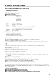
... the U.S. Restart the system as the system will otherwise not be prompted to work with PDK-50HW3 4.1.1 Operating environment a) Operating environment ¶ Supported plasma displays: PDP-504CMX PDP-503CMX PDP-50MXE1 PDP-50MXE1-S PDP-503MXE ¶ Supported computers Model: IBM PC-AT or compatible CPU: Pentium 333 MHz or better Memory: 128 MB Hard disk: About 6 MB...
... the U.S. Restart the system as the system will otherwise not be prompted to work with PDK-50HW3 4.1.1 Operating environment a) Operating environment ¶ Supported plasma displays: PDP-504CMX PDP-503CMX PDP-50MXE1 PDP-50MXE1-S PDP-503MXE ¶ Supported computers Model: IBM PC-AT or compatible CPU: Pentium 333 MHz or better Memory: 128 MB Hard disk: About 6 MB...

Technical Manual
Page 29
... resolution. Detaile Setting: Use to start selected calibration mode. When select Detail-1 or 2, changes the respective screen. Use one of the plasma display. (Read the initial setup instructions for which the value was set calibration is stored and is available atsubsequent startups. ¶ The ...not available when there is available. OK button: Press to perform manual calibration of the plasma display and video card may shift cursor position relative to the resolution for the plasma display in the section "Precautions" in the screen shown below to make the settings ...
... resolution. Detaile Setting: Use to start selected calibration mode. When select Detail-1 or 2, changes the respective screen. Use one of the plasma display. (Read the initial setup instructions for which the value was set calibration is stored and is available atsubsequent startups. ¶ The ...not available when there is available. OK button: Press to perform manual calibration of the plasma display and video card may shift cursor position relative to the resolution for the plasma display in the section "Precautions" in the screen shown below to make the settings ...

Technical Manual
Page 30
... that are available at the center of the screen mode being adjusted appears at current resolution. Installing and Using Software b) Calibration (Detail-2) When the plasma display is still possible to calibrate. 4. "FULL", "4:3" and "DOT BY DOT" modes can be set calibration is stored and is available atsubsequent ..." mode, use the mouse to click the two points, the upper and lower points to verify the display position and adjust the plasma display. Follow the on-screen calibration instructions and touch the points in the upper and lower half of the screen drops during calibration ...
... that are available at the center of the screen mode being adjusted appears at current resolution. Installing and Using Software b) Calibration (Detail-2) When the plasma display is still possible to calibrate. 4. "FULL", "4:3" and "DOT BY DOT" modes can be set calibration is stored and is available atsubsequent ..." mode, use the mouse to click the two points, the upper and lower points to verify the display position and adjust the plasma display. Follow the on-screen calibration instructions and touch the points in the upper and lower half of the screen drops during calibration ...


