Owner's Manual
Page 4
.... 01 Important User Guidance Information 02 Safety Precautions 03 Supplied Accessories Identifying the main units 12 Plasma Display 12 Media Receiver 12 04 Part Names Plasma Display 13 Media Receiver 14 Remote control unit 16 Setting MTS/SAP mode 28 Viewing a channel banner 29 Using the POD service 29 Using the multiscreen functions 29 Splitting the screen 29 Freezing images 30 07 TV Guide On Screen™ System Setup About the TV Guide On Screen™ system...
.... 01 Important User Guidance Information 02 Safety Precautions 03 Supplied Accessories Identifying the main units 12 Plasma Display 12 Media Receiver 12 04 Part Names Plasma Display 13 Media Receiver 14 Remote control unit 16 Setting MTS/SAP mode 28 Viewing a channel banner 29 Using the POD service 29 Using the multiscreen functions 29 Splitting the screen 29 Freezing images 30 07 TV Guide On Screen™ System Setup About the TV Guide On Screen™ system...

Owner's Manual
Page 5
... Connecting a game console or Changing the Channel Display camcorder 69 settings 56 Displaying an image of the game Changing the Default Options 57 console or camcorder 69 11 Adjustments and Settings Sleep Timer 58 AV Selection 58 Basic picture adjustments 59 Advanced picture adjustments 60 Using PureCinema 60 Using Color Temp 60 Using CTI 60 Eliminating noise from images 61 Sound adjustments 61 FOCUS 62 Front Surround 62 Power Control 62 Energy Save 62 No Signal off (AV mode...
... Connecting a game console or Changing the Channel Display camcorder 69 settings 56 Displaying an image of the game Changing the Default Options 57 console or camcorder 69 11 Adjustments and Settings Sleep Timer 58 AV Selection 58 Basic picture adjustments 59 Advanced picture adjustments 60 Using PureCinema 60 Using Color Temp 60 Using CTI 60 Eliminating noise from images 61 Sound adjustments 61 FOCUS 62 Front Surround 62 Power Control 62 Energy Save 62 No Signal off (AV mode...
Owner's Manual
Page 7
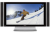
... television). The Pioneer PureVision PDP-5060HD/PDP-4360HD incorporates the latest in order to previous models. Use of the Media Receiver. • Do not invert the product. Plasma Display Systems are not covered by PIONEER. After-image and permanent effects on the screen can be placed in the future during the manufacturing process and in front of the plasma panel, which have static portions). • Avoid viewing...
... television). The Pioneer PureVision PDP-5060HD/PDP-4360HD incorporates the latest in order to previous models. Use of the Media Receiver. • Do not invert the product. Plasma Display Systems are not covered by PIONEER. After-image and permanent effects on the screen can be placed in the future during the manufacturing process and in front of the plasma panel, which have static portions). • Avoid viewing...

Owner's Manual
Page 10
... the power cord from the cart. 10. High voltage flows in proper operating condition. 20. Removing covers can result in the cabinet are not sure of the type of power supply used in this manual in a safe place-These safety and operating instructions must be kept in the instructions must operate on a power source specified on an unstable cart, stand, tripod or table...
... the power cord from the cart. 10. High voltage flows in proper operating condition. 20. Removing covers can result in the cabinet are not sure of the type of power supply used in this manual in a safe place-These safety and operating instructions must be kept in the instructions must operate on a power source specified on an unstable cart, stand, tripod or table...
Owner's Manual
Page 15
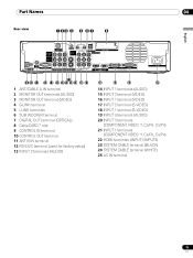
... INPUT 1 INPUT 3 HDMI BLACK WHITE SYSTEM CABLE AC IN 17 9 10 11 12 13 14 1516 18 19 20 21 1 ANT/CABLE A IN terminal 2 MONITOR OUT terminals (AUDIO) 3 MONITOR OUT terminal (VIDEO) 4 G-LINK terminal 5 i.LINK terminals 6 SUB WOOFER terminal 7 DIGITAL OUT terminal (OPTICAL) 8 CableCARD™ slot 9 CONTROL IN terminal 10 CONTROL OUT terminal 11 ANT B IN terminal 12 RS-232C terminal (used for factory setup) 13 INPUT 2 terminals (AUDIO) 22...
... INPUT 1 INPUT 3 HDMI BLACK WHITE SYSTEM CABLE AC IN 17 9 10 11 12 13 14 1516 18 19 20 21 1 ANT/CABLE A IN terminal 2 MONITOR OUT terminals (AUDIO) 3 MONITOR OUT terminal (VIDEO) 4 G-LINK terminal 5 i.LINK terminals 6 SUB WOOFER terminal 7 DIGITAL OUT terminal (OPTICAL) 8 CableCARD™ slot 9 CONTROL IN terminal 10 CONTROL OUT terminal 11 ANT B IN terminal 12 RS-232C terminal (used for factory setup) 13 INPUT 2 terminals (AUDIO) 22...

Owner's Manual
Page 16
...: Sets the sleep timer. NOTE PAGE +/- (for performing operations in the TV Guide On Screen™ system. 12 FREEZE: Freezes a frame from page 80. Mode switch (with "TV" selected) 12 10 INFO: Displays a channel banner when a TV program is displayed. 31 (REC): When using the remote control unit, point it into standby mode. 27 DISPLAY: Displays the channel information. 2 Transmission confirmation LED 28 SCREEN SIZE: Selects the screen size. 3 INPUT: Selects an input source of...
...: Sets the sleep timer. NOTE PAGE +/- (for performing operations in the TV Guide On Screen™ system. 12 FREEZE: Freezes a frame from page 80. Mode switch (with "TV" selected) 12 10 INFO: Displays a channel banner when a TV program is displayed. 31 (REC): When using the remote control unit, point it into standby mode. 27 DISPLAY: Displays the channel information. 2 Transmission confirmation LED 28 SCREEN SIZE: Selects the screen size. 3 INPUT: Selects an input source of...

Owner's Manual
Page 21
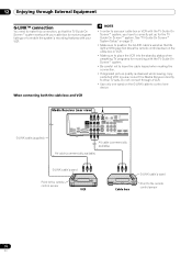
... to view the image received from the Cable Converter. This service presents various types of useful information, using HTML text. 1 Confirm that the ANT/CABLE A IN terminal has been connected with the coaxial cable from the other antenna. • Pressing ANT while watching in the 2-screen mode (TV image and video image) with TV selected will not have any effect. S400 (TS) R-AUDIO-L DIOGPITTAICLASOLUUBT WOOFER Cable CARD WHITE 3 LACK M CABLE Insert...
... to view the image received from the Cable Converter. This service presents various types of useful information, using HTML text. 1 Confirm that the ANT/CABLE A IN terminal has been connected with the coaxial cable from the other antenna. • Pressing ANT while watching in the 2-screen mode (TV image and video image) with TV selected will not have any effect. S400 (TS) R-AUDIO-L DIOGPITTAICLASOLUUBT WOOFER Cable CARD WHITE 3 LACK M CABLE Insert...
Owner's Manual
Page 23
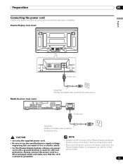
... turn off the power of the Plasma Display and Media Receiver when connecting or disconnecting power cords. • Disconnect the power cord from the power outlet when the Plasma Display System is not going to use the specified power supply voltage; Media Receiver (rear view) MONITOR OUT ANT/ CABLE A IN INPUT 2 G-LINK INPUT 3 S400 (TS) R-AUDIO-L OPTICAL DIGITAL OUT SUB WOOFER Cable CARD I N OUT CONTROL ANT B IN SERVICE ONLY R-AUDIO-L VIDEO S-VIDEO INPUT 1 Y CB / PB COMPONENT VIDEO CR / PR INPUT 1 INPUT 3 HDMI BLACK WHITE SYSTEM CABLE AC IN AC IN Power cord Noise...
... turn off the power of the Plasma Display and Media Receiver when connecting or disconnecting power cords. • Disconnect the power cord from the power outlet when the Plasma Display System is not going to use the specified power supply voltage; Media Receiver (rear view) MONITOR OUT ANT/ CABLE A IN INPUT 2 G-LINK INPUT 3 S400 (TS) R-AUDIO-L OPTICAL DIGITAL OUT SUB WOOFER Cable CARD I N OUT CONTROL ANT B IN SERVICE ONLY R-AUDIO-L VIDEO S-VIDEO INPUT 1 Y CB / PB COMPONENT VIDEO CR / PR INPUT 1 INPUT 3 HDMI BLACK WHITE SYSTEM CABLE AC IN AC IN Power cord Noise...
Owner's Manual
Page 31
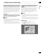
... up the TV Guide On Screen™ system When the Plasma Display System is powered on for satellite services. • Depending on page 32). 31 En Immediately thereafter the TV Guide On Screen™ setup process begins, starting with the Welcome Screen. and/or one week (see Screen 23). Setting up to receive updated TV program listings (see Screen 14). • If you 'll need to display Screen 1 (shown on...
... up the TV Guide On Screen™ system When the Plasma Display System is powered on for satellite services. • Depending on page 32). 31 En Immediately thereafter the TV Guide On Screen™ setup process begins, starting with the Welcome Screen. and/or one week (see Screen 23). Setting up to receive updated TV program listings (see Screen 14). • If you 'll need to display Screen 1 (shown on...
Owner's Manual
Page 39
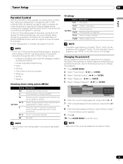
...edited for both conventional and digital TV channels. Examples of programs with a rating of such programs, see pages 41 and 42. Use the following procedure to change the password. 1 Press HOME MENU. 2 Select "Tuner Setup". ( / then ENTER) 3 Select "Parental Control". ( / then ENTER) 4 Select "Password". ( / then ENTER) 5 Select "Change Password". ( / then ENTER) Parental Control Password Password Change Password Clear Password xxxxxxxxxxxxxxxxxxxxx xxxxxxxxxxxxxxxxxxxxx xxxxxxxxxxxxxxxxxxxxx Home Menu Exit 6 Enter the current 4-digit password, using buttons 0 - 9. 8 Enter the same...
...edited for both conventional and digital TV channels. Examples of programs with a rating of such programs, see pages 41 and 42. Use the following procedure to change the password. 1 Press HOME MENU. 2 Select "Tuner Setup". ( / then ENTER) 3 Select "Parental Control". ( / then ENTER) 4 Select "Password". ( / then ENTER) 5 Select "Change Password". ( / then ENTER) Parental Control Password Password Change Password Clear Password xxxxxxxxxxxxxxxxxxxxx xxxxxxxxxxxxxxxxxxxxx xxxxxxxxxxxxxxxxxxxxx Home Menu Exit 6 Enter the current 4-digit password, using buttons 0 - 9. 8 Enter the same...
Owner's Manual
Page 46
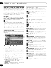
.... For the connections with a VCR or D-VHS recorder, you need to set it up to 24 hours to begin to receive TV program listings. Shows the elapsed time of the TV program. 8 Info Bar - and is cleared. • Remind Off - NOTE • The TV Guide On Screen™ interactive program guide provides listings for the same channel and time every Monday through Friday (manual recording only...
.... For the connections with a VCR or D-VHS recorder, you need to set it up to 24 hours to begin to receive TV program listings. Shows the elapsed time of the TV program. 8 Info Bar - and is cleared. • Remind Off - NOTE • The TV Guide On Screen™ interactive program guide provides listings for the same channel and time every Monday through Friday (manual recording only...
Owner's Manual
Page 67
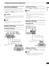
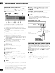
...be actually used. Watching a DVD image Connecting a DVD player Use the INPUT 1 terminals when connecting a DVD player and other audiovisual equipment. MONITOR OUT ANT/ CABLE A IN INPUT 2 G-LINK INPUT 3 S400 (TS) R-AUDIO-L OPTICAL DIGITAL OUT SUB WOOFER Media Receiver (rear view) SERVICE ONLY R-AUDIO-L VIDEO S-VIDEO INPUT 1 Y CB / PB COMPONENT VIDEO CR / PR INPUT 1 HD Displaying a DVD image To watch a VCR image, press INPUT 2 on the remote control unit or press INPUT on the Media Receiver. NOTE • Refer to the relevant instruction manual (DVD player, personal...
...be actually used. Watching a DVD image Connecting a DVD player Use the INPUT 1 terminals when connecting a DVD player and other audiovisual equipment. MONITOR OUT ANT/ CABLE A IN INPUT 2 G-LINK INPUT 3 S400 (TS) R-AUDIO-L OPTICAL DIGITAL OUT SUB WOOFER Media Receiver (rear view) SERVICE ONLY R-AUDIO-L VIDEO S-VIDEO INPUT 1 Y CB / PB COMPONENT VIDEO CR / PR INPUT 1 HD Displaying a DVD image To watch a VCR image, press INPUT 2 on the remote control unit or press INPUT on the Media Receiver. NOTE • Refer to the relevant instruction manual (DVD player, personal...

Owner's Manual
Page 68
... of digital video signals when digital video signals are not supported. Item Description Auto Automatically identifies input digital video signals. (factory default) Color-1 Digital Component Video signals (4:2:2) locked Color-2 Digital Component Video signals (4:4:4) locked Color-3 Digital RGB signals locked 6 Press HOME MENU to select INPUT 1 (or INPUT 3). 12 Enjoying through External Equipment Using HDMI Input The INPUT 1 and INPUT 3 terminals include HDMI terminals to which digital video and audio signals can be received from the connected equipment. Input signal...
... of digital video signals when digital video signals are not supported. Item Description Auto Automatically identifies input digital video signals. (factory default) Color-1 Digital Component Video signals (4:2:2) locked Color-2 Digital Component Video signals (4:4:4) locked Color-3 Digital RGB signals locked 6 Press HOME MENU to select INPUT 1 (or INPUT 3). 12 Enjoying through External Equipment Using HDMI Input The INPUT 1 and INPUT 3 terminals include HDMI terminals to which digital video and audio signals can be received from the connected equipment. Input signal...
Owner's Manual
Page 70
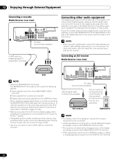
... watching images played back on a VCR connected to the MONITOR OUT terminals, select an input source (e.g., TV channel reception) on the recording equipment other audio equipment The digital audio output terminal (optical) on this system can output Dolby Digital signals. NOTE • When using the digital audio output terminal (optical), you need to make settings depending on the AV receiver. Selecting an external input source may result in high quality. G-LINK cable (for presetting digital TV programs for recording...
... watching images played back on a VCR connected to the MONITOR OUT terminals, select an input source (e.g., TV channel reception) on the recording equipment other audio equipment The digital audio output terminal (optical) on this system can output Dolby Digital signals. NOTE • When using the digital audio output terminal (optical), you need to make settings depending on the AV receiver. Selecting an external input source may result in high quality. G-LINK cable (for presetting digital TV programs for recording...
Owner's Manual
Page 71
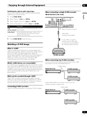
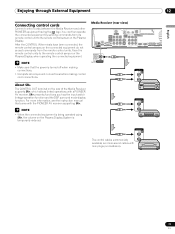
... programs. You cannot record conventional TV channels nor contents coming from external input sources and personal computers. i.LINK cable Media Receiver STANDBY/ON REC ON STANDBY TIMER PULL OPEN D-VHS recorder D-VHS recorder 71 En Enjoying through External Equipment 12 English Switching the optical audio signal type Set up for the DIGITAL AUDIO output terminal (OPTICAL), depending on the rear of the Media Receiver. Dolby Digital For Dolby Digital encoded signals, outputs in the PCM format. When connecting a single D-VHS recorder Media Receiver (rear view) MONITOR...
... programs. You cannot record conventional TV channels nor contents coming from external input sources and personal computers. i.LINK cable Media Receiver STANDBY/ON REC ON STANDBY TIMER PULL OPEN D-VHS recorder D-VHS recorder 71 En Enjoying through External Equipment 12 English Switching the optical audio signal type Set up for the DIGITAL AUDIO output terminal (OPTICAL), depending on the rear of the Media Receiver. Dolby Digital For Dolby Digital encoded signals, outputs in the PCM format. When connecting a single D-VHS recorder Media Receiver (rear view) MONITOR...
Owner's Manual
Page 72
... Media Receiver STANDBY/ON REC ON STANDBY TIMER PULL OPEN D-VHS recorder Displaying a D-VHS image To watch a D-VHS image, press i.LINK on the remote control unit or press INPUT on VHS tape, S-VHS tape, or (if with your D-VHS recorder. 72 En Do not connect or disconnect the i.LINK cable from external input sources. • This system can control one D-VHS recorder connected through i.LINK is recording or playing...
... Media Receiver STANDBY/ON REC ON STANDBY TIMER PULL OPEN D-VHS recorder Displaying a D-VHS image To watch a D-VHS image, press i.LINK on the remote control unit or press INPUT on VHS tape, S-VHS tape, or (if with your D-VHS recorder. 72 En Do not connect or disconnect the i.LINK cable from external input sources. • This system can control one D-VHS recorder connected through i.LINK is recording or playing...
Owner's Manual
Page 74
... of inserted video tape; To select a button on the control panel screen, press / or / , and then press ENTER on the Media Receiver to these terminals, the same signal type is the case, connect i.LINK devices. • If none of the next program. 18 Forwards the tape. 19 Exits the control panel screen and displays the i.LINK Setup menu. 20 Allows you have set up to use . After pressing...
... of inserted video tape; To select a button on the control panel screen, press / or / , and then press ENTER on the Media Receiver to these terminals, the same signal type is the case, connect i.LINK devices. • If none of the next program. 18 Forwards the tape. 19 Exits the control panel screen and displays the i.LINK Setup menu. 20 Allows you have set up to use . After pressing...
Owner's Manual
Page 76
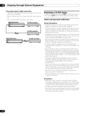
... connecting both the cable box and VCR G-LINK cable (supplied) Media Receiver (rear view) MONITOR OUT ANT/ CABLE A IN INPUT 2 G-LINK INPUT 3 S400 (TS) R-AUDIO-L OPTICAL DIGITAL OUT SUB WOOFER Cable CAR I N OUT CONTROL ANT B IN SERVICE ONLY R-AUDIO-L VIDEO S-VIDEO INPUT 1 Y CB / PB COMPONENT VIDEO CR / PR INPUT 1 INPUT 3 HDMI AV cable (commercially available) AV cable (commercially available) G-LINK cable's wand Point to the remote control sensor VCR Cable box G-LINK cable's wand Point to place the VCR into the standby status when presetting TV programs...
... connecting both the cable box and VCR G-LINK cable (supplied) Media Receiver (rear view) MONITOR OUT ANT/ CABLE A IN INPUT 2 G-LINK INPUT 3 S400 (TS) R-AUDIO-L OPTICAL DIGITAL OUT SUB WOOFER Cable CAR I N OUT CONTROL ANT B IN SERVICE ONLY R-AUDIO-L VIDEO S-VIDEO INPUT 1 Y CB / PB COMPONENT VIDEO CR / PR INPUT 1 INPUT 3 HDMI AV cable (commercially available) AV cable (commercially available) G-LINK cable's wand Point to the remote control sensor VCR Cable box G-LINK cable's wand Point to place the VCR into the standby status when presetting TV programs...
Owner's Manual
Page 77
... power is being operated using SR+, the volume on the Plasma Display. NOTE • When the connected equipment is turned off when making connections. • Complete all component connections before making control cord connections. NOTE • Make sure that came with the PIONEER AV receiver supporting SR+. You can then operate the connected equipment by sending commands from the remote control units. Media Receiver (rear view) CONTROL MONITOR OUT ANT/ CABLE A IN INPUT 2 G-LINK INPUT 3 S400 (TS) R-AUDIO-L OPTICAL DIGITAL...
... power is being operated using SR+, the volume on the Plasma Display. NOTE • When the connected equipment is turned off when making connections. • Complete all component connections before making control cord connections. NOTE • Make sure that came with the PIONEER AV receiver supporting SR+. You can then operate the connected equipment by sending commands from the remote control units. Media Receiver (rear view) CONTROL MONITOR OUT ANT/ CABLE A IN INPUT 2 G-LINK INPUT 3 S400 (TS) R-AUDIO-L OPTICAL DIGITAL...
Owner's Manual
Page 85
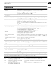
... error codes appear on the Plasma Display. (See page 22.) • Are you using a video or PC input source, check that is too bright. • Power is suddenly turned off. • Is the sleep timer set correctly? Check temperature around media receiver. Check temperature around PDP. Internal temperature too high. Powering off . Powering off . only audio is reversed between the right and • Check if the speaker cable connections have selected "Picture...
... error codes appear on the Plasma Display. (See page 22.) • Are you using a video or PC input source, check that is too bright. • Power is suddenly turned off. • Is the sleep timer set correctly? Check temperature around media receiver. Check temperature around PDP. Internal temperature too high. Powering off . Powering off . only audio is reversed between the right and • Check if the speaker cable connections have selected "Picture...


