
Owner's Manual
Page 5
... a DVD image 50 Connecting a DVD player 50 Displaying a DVD image 50 Watching a VCR image 50 Connecting a VCR 50 Displaying a VCR image 50 Using HDMI Input 51 Connecting HDMI equipment 51 Enjoying a game console or watching camcorder images 52 Connecting a game console or camcorder 52 Displaying an image of the game console or...
... a DVD image 50 Connecting a DVD player 50 Displaying a DVD image 50 Watching a VCR image 50 Connecting a VCR 50 Displaying a VCR image 50 Using HDMI Input 51 Connecting HDMI equipment 51 Enjoying a game console or watching camcorder images 52 Connecting a game console or camcorder 52 Displaying an image of the game console or...
Owner's Manual
Page 13
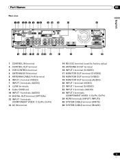
... 1 COMPONENT VIDEO R-AUDIO-L Y CB/PB CR/PR SERVICE ONLY OUT MONITOR OUT S-VIDEO VIDEO R-AUDIO-L S-VIDEO R-AUDIO-L IINNPPUUTT 33 Y CB/PB CR/PR INPUT 1 INPUT 3 HDMI 13 AC IN BLACK WHITE SYSTEM CABLE English 05 14 15 16 17 18 19 20 21 22 23 24 25 26 1 CONTROL IN terminal... OUT terminals (AUDIO) 20 INPUT 1 terminal (VIDEO) 21 INPUT 1 terminal (S-VIDEO) 22 INPUT 3 terminals (AUDIO) 23 INPUT 3 terminals (COMPONENT VIDEO: Y, CB/PB, CR/PR) 24 HDMI terminals (INPUT1/INPUT3) 25 SYSTEM CABLE terminal (WHITE) 26 SYSTEM CABLE terminal (BLACK) 13 En
... 1 COMPONENT VIDEO R-AUDIO-L Y CB/PB CR/PR SERVICE ONLY OUT MONITOR OUT S-VIDEO VIDEO R-AUDIO-L S-VIDEO R-AUDIO-L IINNPPUUTT 33 Y CB/PB CR/PR INPUT 1 INPUT 3 HDMI 13 AC IN BLACK WHITE SYSTEM CABLE English 05 14 15 16 17 18 19 20 21 22 23 24 25 26 1 CONTROL IN terminal... OUT terminals (AUDIO) 20 INPUT 1 terminal (VIDEO) 21 INPUT 1 terminal (S-VIDEO) 22 INPUT 3 terminals (AUDIO) 23 INPUT 3 terminals (COMPONENT VIDEO: Y, CB/PB, CR/PR) 24 HDMI terminals (INPUT1/INPUT3) 25 SYSTEM CABLE terminal (WHITE) 26 SYSTEM CABLE terminal (BLACK) 13 En
Owner's Manual
Page 18
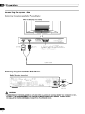
... Connecting the system cable Connecting the system cable to the Plasma Display Plasma Display (rear view) (WHITE) (BLACK) For details on optional PIONEER speaker installation, refer to the Media Receiver Media Receiver (rear view) IN OUT VCR CONTROL CONTROL IN ANTENNA B ANTENNA/ CABLE A IN Cable...CB/PB CR/PR SERVICE ONLY OUT MONITOR OUT S-VIDEO VIDEO R-AUDIO-L S-VIDEO R-AUDIO-L IINNPUTT 33 Y CB/PB CR/PR INPUT 1 INPUT 3 HDMI AC IN BLACK WHITE SYSTEM CABLE (BLACK) (WHITE) • THESE SPEAKER TERMINALS CAN BE APPLIED WITH HAZARDOUS VOLTAGE WHEN YOU CONNECT OR DISCONNECT THE ...
... Connecting the system cable Connecting the system cable to the Plasma Display Plasma Display (rear view) (WHITE) (BLACK) For details on optional PIONEER speaker installation, refer to the Media Receiver Media Receiver (rear view) IN OUT VCR CONTROL CONTROL IN ANTENNA B ANTENNA/ CABLE A IN Cable...CB/PB CR/PR SERVICE ONLY OUT MONITOR OUT S-VIDEO VIDEO R-AUDIO-L S-VIDEO R-AUDIO-L IINNPUTT 33 Y CB/PB CR/PR INPUT 1 INPUT 3 HDMI AC IN BLACK WHITE SYSTEM CABLE (BLACK) (WHITE) • THESE SPEAKER TERMINALS CAN BE APPLIED WITH HAZARDOUS VOLTAGE WHEN YOU CONNECT OR DISCONNECT THE ...
Owner's Manual
Page 23
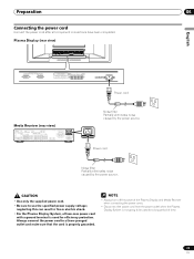
... 1 COMPONENT VIDEO R-AUDIO-L Y CB/PB CR/PR SERVICE ONLY OUT MONITOR OUT S-VIDEO VIDEO R-AUDIO-L S-VIDEO R-AUDIO-L IINNPPUUTT 33 Y CB/PB CR/PR INPUT 1 INPUT 3 HDMI ACACINILNET BLACK WHITE SYSTEM CABLE Noise filter Partially eliminates noise caused by the power source. • Use only the supplied power cord. • Be sure...
... 1 COMPONENT VIDEO R-AUDIO-L Y CB/PB CR/PR SERVICE ONLY OUT MONITOR OUT S-VIDEO VIDEO R-AUDIO-L S-VIDEO R-AUDIO-L IINNPPUUTT 33 Y CB/PB CR/PR INPUT 1 INPUT 3 HDMI ACACINILNET BLACK WHITE SYSTEM CABLE Noise filter Partially eliminates noise caused by the power source. • Use only the supplied power cord. • Be sure...
Owner's Manual
Page 30
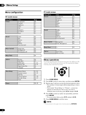
... 43 44 40 45 45 Menu operations The following describes the typical procedure for setting up the menus. Option Tuner Setup Timers Position Side Mask HDMI Input Monitor Out Digital Audio Out Language Channel Setup Parental Control Favorites Closed Captions Recorder Setup Clock - 30 En Page 40 41 41 41 41...
... 43 44 40 45 45 Menu operations The following describes the typical procedure for setting up the menus. Option Tuner Setup Timers Position Side Mask HDMI Input Monitor Out Digital Audio Out Language Channel Setup Parental Control Favorites Closed Captions Recorder Setup Clock - 30 En Page 40 41 41 41 41...
Owner's Manual
Page 50
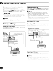
...S400 VIDEO INPUT 1 COMPONENT VIDEO R-AUDIO-L Y CB/PB CR/PR VIDEO R-AUDIO-L S-VIDEO R-AUDIO-L INPUT 3 Y CB/PB CR/PR INPUT 1 HDMI S-Video cable (commercially available) Connecting a VCR Use the INPUT 2 terminals when connecting a VCR and other audiovisual equipment. To view images coming from external...CB/PB CR/PR SERVICE ONLY OUT MONITOR OUT S-VIDEO VIDEO R-AUDIO-L S-VIDEO R-AUDIO-L IINNPUTT 33 Y CB/PB CR/PR INPUT 1 INPUT HDMI AV cable (commercially available) S-Video cable (commercially available) DVD player VCR Displaying a VCR image To watch a DVD image, press INPUT 1 on...
...S400 VIDEO INPUT 1 COMPONENT VIDEO R-AUDIO-L Y CB/PB CR/PR VIDEO R-AUDIO-L S-VIDEO R-AUDIO-L INPUT 3 Y CB/PB CR/PR INPUT 1 HDMI S-Video cable (commercially available) Connecting a VCR Use the INPUT 2 terminals when connecting a VCR and other audiovisual equipment. To view images coming from external...CB/PB CR/PR SERVICE ONLY OUT MONITOR OUT S-VIDEO VIDEO R-AUDIO-L S-VIDEO R-AUDIO-L IINNPUTT 33 Y CB/PB CR/PR INPUT 1 INPUT HDMI AV cable (commercially available) S-Video cable (commercially available) DVD player VCR Displaying a VCR image To watch a DVD image, press INPUT 1 on...
Owner's Manual
Page 51
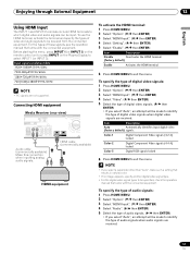
... types to exit the menu. For the types of these signals, see the operation manual that came with the connected equipment. Connecting HDMI equipment Media Receiver (rear view) DIGITAL OUT OPTICAL (TS) S400 VIDEO INPUT 1 COMPONENT VIDEO R-AUDIO-L Y CB/PB CR/PR... S-VIDEO R-AUDIO-L IINNPUTT 33 Y CB/PB CR/PR INPUT 1 INPUT 3 HDMI Audio cable (commercially available) Make this connection when inputting analog audio signals. Color-1 Digital Component Video signals (4:2:2) locked Color-2 Digital Component Video signals...
... types to exit the menu. For the types of these signals, see the operation manual that came with the connected equipment. Connecting HDMI equipment Media Receiver (rear view) DIGITAL OUT OPTICAL (TS) S400 VIDEO INPUT 1 COMPONENT VIDEO R-AUDIO-L Y CB/PB CR/PR... S-VIDEO R-AUDIO-L IINNPUTT 33 Y CB/PB CR/PR INPUT 1 INPUT 3 HDMI Audio cable (commercially available) Make this connection when inputting analog audio signals. Color-1 Digital Component Video signals (4:2:2) locked Color-2 Digital Component Video signals...
Owner's Manual
Page 53
... an external input source may result in distorted images or noise. • Analog broadcasting signals are being input 5 Digital video and audio signals from the HDMI terminals • When watching images played back on a VCR or DVD recorder connected to make settings depending on the rear of composite signals coming from...
... an external input source may result in distorted images or noise. • Analog broadcasting signals are being input 5 Digital video and audio signals from the HDMI terminals • When watching images played back on a VCR or DVD recorder connected to make settings depending on the rear of composite signals coming from...
Owner's Manual
Page 54
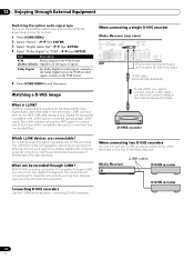
... 1 COMPONENT VIDEO R-AUDIO-L Y CB/PB CR/PR OUT ITOR OUT S-VIDEO VIDEO R-AUDIO-L S-VIDEO R-AUDIO-L INPUT 3 Y CB/PB CR/PR INPUT 1 IN HDMI (The function and performance are connectable? The i.LINK terminals on your AV receiver. 1 Press HOME MENU. 2 Select "Option". ( / then ENTER) 3 Select "Digital... specifications. Watching a D-VHS image What is a digital serial interface for the IEEE 1394 data transport bus. For i.LINK devices, this PDP system to control one of signals. i.LINK is i.LINK? Dolby Digital For Dolby Digital encoded signals, outputs in the PCM format. 5...
... 1 COMPONENT VIDEO R-AUDIO-L Y CB/PB CR/PR OUT ITOR OUT S-VIDEO VIDEO R-AUDIO-L S-VIDEO R-AUDIO-L INPUT 3 Y CB/PB CR/PR INPUT 1 IN HDMI (The function and performance are connectable? The i.LINK terminals on your AV receiver. 1 Press HOME MENU. 2 Select "Option". ( / then ENTER) 3 Select "Digital... specifications. Watching a D-VHS image What is a digital serial interface for the IEEE 1394 data transport bus. For i.LINK devices, this PDP system to control one of signals. i.LINK is i.LINK? Dolby Digital For Dolby Digital encoded signals, outputs in the PCM format. 5...
Owner's Manual
Page 61
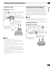
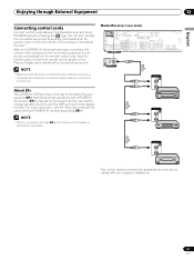
... the Media Receiver. CONTROL IN OUT CONTROL IN OUT CONTROL IN OUT The control cables (commercially available) are mono sound cables with a PIONEER AV receiver. About SR+ The CONTROL OUT terminal on the Plasma Display when operating the connected equipment. Enjoying through SR+, the volume on...Y CB/PB CR/PR SERVICE ONLY OUT MONITOR OUT S-VIDEO VIDEO R-AUDIO-L S-VIDEO R-AUDIO-L IINNPUTT 33 Y CB/PB CR/PR INPUT 1 INPUT 3 HDMI IN OUT CONTROL • Make sure that allows linked operations with mini plugs (no resistance). 61 En SR+ presents functions such as the input switch...
... the Media Receiver. CONTROL IN OUT CONTROL IN OUT CONTROL IN OUT The control cables (commercially available) are mono sound cables with a PIONEER AV receiver. About SR+ The CONTROL OUT terminal on the Plasma Display when operating the connected equipment. Enjoying through SR+, the volume on...Y CB/PB CR/PR SERVICE ONLY OUT MONITOR OUT S-VIDEO VIDEO R-AUDIO-L S-VIDEO R-AUDIO-L IINNPUTT 33 Y CB/PB CR/PR INPUT 1 INPUT 3 HDMI IN OUT CONTROL • Make sure that allows linked operations with mini plugs (no resistance). 61 En SR+ presents functions such as the input switch...

Owner's Manual
Page 79
Appendix 14 English Specifications Item Number of Pixels Audio Amplifier Surround System Power Requirement Dimensions Weight 50"Plasma Display, Model: PDP-505PU/PDP-504PU 43" Plasma Display, Model: PDP-435PU/PDP-434PU 1280 × 768 pixels 1024 × 768 pixels 13 W + 13 W (1 kHz, 10 %, 8 Ω) 13 W + 13 W (1 kHz, ... (TS) S400 (2) INPUT 1 COMPONENT VIDEO in, S-VIDEO in, VIDEO in, AUDIO in, HDMI in INPUT 2 S-VIDEO in, VIDEO in, AUDIO in INPUT 3 COMPONENT VIDEO in, AUDIO in, HDMI in Monitor Out S-VIDEO out, VIDEO out, AUDIO out Digital Audio Output Optical (1) VCR Control ...
Appendix 14 English Specifications Item Number of Pixels Audio Amplifier Surround System Power Requirement Dimensions Weight 50"Plasma Display, Model: PDP-505PU/PDP-504PU 43" Plasma Display, Model: PDP-435PU/PDP-434PU 1280 × 768 pixels 1024 × 768 pixels 13 W + 13 W (1 kHz, 10 %, 8 Ω) 13 W + 13 W (1 kHz, ... (TS) S400 (2) INPUT 1 COMPONENT VIDEO in, S-VIDEO in, VIDEO in, AUDIO in, HDMI in INPUT 2 S-VIDEO in, VIDEO in, AUDIO in INPUT 3 COMPONENT VIDEO in, AUDIO in, HDMI in Monitor Out S-VIDEO out, VIDEO out, AUDIO out Digital Audio Output Optical (1) VCR Control ...

Owner's Manual
Page 80
...fonts licensed by U.S. Published by Macrovision. "Dolby" and the double-D symbol are trademarks of Dolby Laboratories. • HDMI, the HDMI logo and High-Definition Multimedia Interface are trademarks or registered trademarks of SRS Labs, Inc. Copyright protection • This... product incorporates copyright protection technology that is prohibited. Copyright © 2004 Pioneer Corporation. 14 Appendix Trademarks • FOCUS, WOW,...
...fonts licensed by U.S. Published by Macrovision. "Dolby" and the double-D symbol are trademarks of Dolby Laboratories. • HDMI, the HDMI logo and High-Definition Multimedia Interface are trademarks or registered trademarks of SRS Labs, Inc. Copyright protection • This... product incorporates copyright protection technology that is prohibited. Copyright © 2004 Pioneer Corporation. 14 Appendix Trademarks • FOCUS, WOW,...

Owner's Manual
Page 93
... 1 COMPONENT VIDEO R-AUDIO-L Y CB/PB CR/PR SERVICE ONLY OUT MONITOR OUT S-VIDEO VIDEO R-AUDIO-L S-VIDEO R-AUDIO-L IINNPPUUTT 33 Y CB/PB CR/PR INPUT 1 INPUT 3 HDMI 13 AC IN BLACK WHITE SYSTEM CABLE 05 Français 14 15 16 17 18 19 20 21 22 23 24 25 26 1 Prise... OUT (AUDIO) 20 Prise INPUT 1 (VIDEO) 21 Prise INPUT 1 (S-VIDEO) 22 Prises INPUT 3 (AUDIO) 23 Prises INPUT 3 (COMPONENT VIDEO: Y, CB/PB, CR/PR) 24 Prises HDMI (INPUT1/INPUT3) 25 Prise SYSTEM CABLE (BLANC) 26 Prise SYSTEM CABLE (NOIR) 13 Fr
... 1 COMPONENT VIDEO R-AUDIO-L Y CB/PB CR/PR SERVICE ONLY OUT MONITOR OUT S-VIDEO VIDEO R-AUDIO-L S-VIDEO R-AUDIO-L IINNPPUUTT 33 Y CB/PB CR/PR INPUT 1 INPUT 3 HDMI 13 AC IN BLACK WHITE SYSTEM CABLE 05 Français 14 15 16 17 18 19 20 21 22 23 24 25 26 1 Prise... OUT (AUDIO) 20 Prise INPUT 1 (VIDEO) 21 Prise INPUT 1 (S-VIDEO) 22 Prises INPUT 3 (AUDIO) 23 Prises INPUT 3 (COMPONENT VIDEO: Y, CB/PB, CR/PR) 24 Prises HDMI (INPUT1/INPUT3) 25 Prise SYSTEM CABLE (BLANC) 26 Prise SYSTEM CABLE (NOIR) 13 Fr


