Operating Instructions
Page 5
... only with a polarized alternating current line plug (a plug having a third (grounding) pin, it will often require extensive work by the operating instructions as an improper adjustment of power source indicated on an unstable cart, stand, tripod, bracket, or table. When installing an outside antenna or cable system is connected to the product, be sure the antenna or cable system is left unused for service. SERVICING - For added protection for...
... only with a polarized alternating current line plug (a plug having a third (grounding) pin, it will often require extensive work by the operating instructions as an improper adjustment of power source indicated on an unstable cart, stand, tripod, bracket, or table. When installing an outside antenna or cable system is connected to the product, be sure the antenna or cable system is left unused for service. SERVICING - For added protection for...
Operating Instructions
Page 7
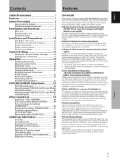
... use this manual 3 Checking supplied accessories 5 Part Names and Functions 6 Main unit 6 Remote control unit 7 Connection panel 8 Installation and Connections 10 Installation of the unit 10 Connection to a personal computer 12 Audio connections 13 Power cord connection 14 How to route cables 15 System Settings 16 Setting the onscreen display language 16 Settings after connections 17 Operation 19 Selecting input source 19 Adjusting sound volume 20 Muting the sound 20 Confirming current status 20 Changing screen size 21 Enlarging one part of the screen...
... use this manual 3 Checking supplied accessories 5 Part Names and Functions 6 Main unit 6 Remote control unit 7 Connection panel 8 Installation and Connections 10 Installation of the unit 10 Connection to a personal computer 12 Audio connections 13 Power cord connection 14 How to route cables 15 System Settings 16 Setting the onscreen display language 16 Settings after connections 17 Operation 19 Selecting input source 19 Adjusting sound volume 20 Muting the sound 20 Confirming current status 20 Changing screen size 21 Enlarging one part of the screen...
Operating Instructions
Page 8
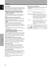
... and screen size settings supported include [DOT BY DOT], [4:3], [FULL] and [ZOOM](*1). * Supported signals are attached, the operation panel on input signal. ¶ Free Installation Configuration - While producing a large 43" screen image, the display is reduced by Pioneer. Some of these include the one-touch screen adjustment, [AUTO SET UP] function for computer connections, and the POINT ZOOM function to enlarge local portions of the screen image to display important detailed program data. ¶ Power...
... and screen size settings supported include [DOT BY DOT], [4:3], [FULL] and [ZOOM](*1). * Supported signals are attached, the operation panel on input signal. ¶ Free Installation Configuration - While producing a large 43" screen image, the display is reduced by Pioneer. Some of these include the one-touch screen adjustment, [AUTO SET UP] function for computer connections, and the POINT ZOOM function to enlarge local portions of the screen image to display important detailed program data. ¶ Power...
Operating Instructions
Page 9
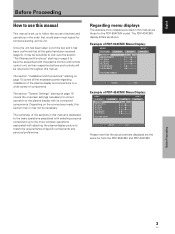
... unit. The PDP-434CMX display differs as their respective buttons and controls will be referred to throughout this section may or may be necessary. Depending on page 6 to become acquainted with the plasma monitor and remote control unit, as shown: Example of specific components and personal preferences. The section "Installation and Connections" starting on the connections made, this manual. E N H A N C E : SETUP 0 0 0 0 0 0 0 INPUT1 OPTION PICTURE RESET SET ENTER MENU EXIT Example...
... unit. The PDP-434CMX display differs as their respective buttons and controls will be referred to throughout this section may or may be necessary. Depending on page 6 to become acquainted with the plasma monitor and remote control unit, as shown: Example of specific components and personal preferences. The section "Installation and Connections" starting on the connections made, this manual. E N H A N C E : SETUP 0 0 0 0 0 0 0 INPUT1 OPTION PICTURE RESET SET ENTER MENU EXIT Example...
Operating Instructions
Page 12
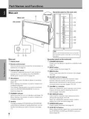
... optional speakers have been connected, the operation panel on the main unit PDP-434CMX 6 6 7 8 9 0 - = ~ ! it is enabled when the [ENERGY SAVE] option is used to display the current set to 33). - When flashing, the indicator is in operation or standby mode (page 19). 8 INPUT button Press to select the input (page 19). 9 MENU button Press to open and close the on-screen menu (pages 16 to 33). 0 ADJUST ( / / / ) buttons Use these buttons are...
... optional speakers have been connected, the operation panel on the main unit PDP-434CMX 6 6 7 8 9 0 - = ~ ! it is enabled when the [ENERGY SAVE] option is used to display the current set to 33). - When flashing, the indicator is in operation or standby mode (page 19). 8 INPUT button Press to select the input (page 19). 9 MENU button Press to open and close the on-screen menu (pages 16 to 33). 0 ADJUST ( / / / ) buttons Use these buttons are...
Operating Instructions
Page 15
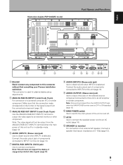
... in standby mode. (page 12) 6 AUDIO (INPUT1) (Stereo mini jack) Use to obtain sound when INPUT1 is used for plasma display setup adjustments. 4 ANALOG RGB IN (INPUT1) (mini D-sub 15 pin) For connection of copyguard-protected video signals (page 12). 8 AUDIO (INPUT2) (Stereo mini jack) Use to connect a computer. AC IN Use to connect the supplied power cord to an AV amplifier or similar component. This connector is selected. Connect the audio output jack...
... in standby mode. (page 12) 6 AUDIO (INPUT1) (Stereo mini jack) Use to obtain sound when INPUT1 is used for plasma display setup adjustments. 4 ANALOG RGB IN (INPUT1) (mini D-sub 15 pin) For connection of copyguard-protected video signals (page 12). 8 AUDIO (INPUT2) (Stereo mini jack) Use to connect a computer. AC IN Use to connect the supplied power cord to an AV amplifier or similar component. This connector is selected. Connect the audio output jack...

Operating Instructions
Page 18
... DVI-D INPUT2 AUDIO Installation and Connections Connect the cable corresponding to INPUT1. ¶ See Appendix 1 (pages 38 and 40) for information regarding signals and display formats supported by tightening the terminal screws on the computer type. For details, please read the computer's instruction manual. NOTICE ¶ INPUT2 supports Microsoft "Plug & Play" (VESA DDC 2B) components. See Appendix 2-1/2 (page 42) when making connections to the video card's DVI connector. Following completing connections, on -screen setup...
... DVI-D INPUT2 AUDIO Installation and Connections Connect the cable corresponding to INPUT1. ¶ See Appendix 1 (pages 38 and 40) for information regarding signals and display formats supported by tightening the terminal screws on the computer type. For details, please read the computer's instruction manual. NOTICE ¶ INPUT2 supports Microsoft "Plug & Play" (VESA DDC 2B) components. See Appendix 2-1/2 (page 42) when making connections to the video card's DVI connector. Following completing connections, on -screen setup...
Operating Instructions
Page 21
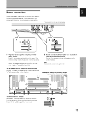
... with this unit for bunching cables together. To attach the speed clamps to fix the clamp. Please attach carefully. Installation and Connections To remove speed clamps Using pliers, twist the clamp 90° and pull it outward. Illustration depicts PDP-504CMX model. * As viewed from the rear of 1 to the main unit Connect the speed clamps using the provided speed clamps. Once...
... with this unit for bunching cables together. To attach the speed clamps to fix the clamp. Please attach carefully. Installation and Connections To remove speed clamps Using pliers, twist the clamp 90° and pull it outward. Illustration depicts PDP-504CMX model. * As viewed from the rear of 1 to the main unit Connect the speed clamps using the provided speed clamps. Once...
Operating Instructions
Page 22
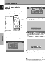
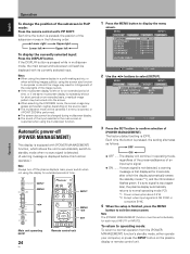
... to turn the power ON. The ON indicator on the front panel will light green. 3 Press the MENU button to display the menu screen. MENU INPUT1 PICTURE SCREEN SETUP OPTION LANGUAGE ENERGY SAVE SCREEN MGT. STANDBY/ ON MENU 5/∞ STANDBY/ ON 2/3 SET MENU 2/3 SET 5/∞ Main unit operating panel Remote control unit 1 Set the rear panel MAIN POWER switch to select [LANGUAGE], then press the SET button. ORBITER MASK CONTROL AUTO SET UP MODE AUTO FUNCTION AUDIO OUT : ENGLISH : STANDARD : OFF : OFF : ON : INACTIVE : OFF : FIXED SET ENTER MENU EXIT 5 Use...
... to turn the power ON. The ON indicator on the front panel will light green. 3 Press the MENU button to display the menu screen. MENU INPUT1 PICTURE SCREEN SETUP OPTION LANGUAGE ENERGY SAVE SCREEN MGT. STANDBY/ ON MENU 5/∞ STANDBY/ ON 2/3 SET MENU 2/3 SET 5/∞ Main unit operating panel Remote control unit 1 Set the rear panel MAIN POWER switch to select [LANGUAGE], then press the SET button. ORBITER MASK CONTROL AUTO SET UP MODE AUTO FUNCTION AUDIO OUT : ENGLISH : STANDARD : OFF : OFF : ON : INACTIVE : OFF : FIXED SET ENTER MENU EXIT 5 Use...
Operating Instructions
Page 23
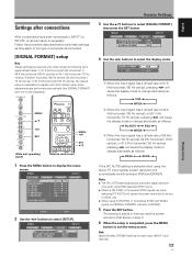
...screen setup is necessary for each input (INPUT1 and INPUT2). 17 En System Settings English Settings after connections After components have been connected to exit the menu screen. E N H A N C E : SETUP 0 0 0 0 0 0 0 OPTION PICTURE RESET SET ENTER MENU EXIT 2 Use the 2/3 buttons to select the display mode. MENU INPUT1 PICTURE SCREEN SETUP OPTION POWER MANAGEMENT CLAMP POSITION SIGNAL FORMAT : OFF : AUTO : VGA 4 Use the 2/3 buttons to select [SETUP]. MENU 5/∞ 2/3 SET MENU 2/3 SET 5/∞ Main unit operating panel Remote control unit 1 Press the MENU button...
...screen setup is necessary for each input (INPUT1 and INPUT2). 17 En System Settings English Settings after connections After components have been connected to exit the menu screen. E N H A N C E : SETUP 0 0 0 0 0 0 0 OPTION PICTURE RESET SET ENTER MENU EXIT 2 Use the 2/3 buttons to select the display mode. MENU INPUT1 PICTURE SCREEN SETUP OPTION POWER MANAGEMENT CLAMP POSITION SIGNAL FORMAT : OFF : AUTO : VGA 4 Use the 2/3 buttons to select [SETUP]. MENU 5/∞ 2/3 SET MENU 2/3 SET 5/∞ Main unit operating panel Remote control unit 1 Press the MENU button...
Operating Instructions
Page 24
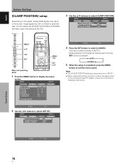
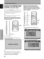
...: SETUP 0 0 0 0 0 0 0 OPTION PICTURE RESET SET ENTER MENU EXIT 2 Use the 2/3 buttons to [LOCKED]. MENU INPUT1 PICTURE SCREEN SETUP OPTION POWER MANAGEMENT CLAMP POSITION SIGNAL FORMAT : OFF : AUTO : VGA MENU 5/∞ 2/3 SET MENU 2/3 SET 5/∞ Main unit operating panel Remote control unit 1 Press the MENU button to select [LOCKED]. MENU INPUT1 PICTURE SCREEN SETUP OPTION POWER MANAGEMENT CLAMP POSITION SIGNAL FORMAT : OFF : AUTO : VGA SET CHANGE MENU EXIT 4 Press the SET button to display the menu screen. English System Settings [CLAMP POSITION] setup...
...: SETUP 0 0 0 0 0 0 0 OPTION PICTURE RESET SET ENTER MENU EXIT 2 Use the 2/3 buttons to [LOCKED]. MENU INPUT1 PICTURE SCREEN SETUP OPTION POWER MANAGEMENT CLAMP POSITION SIGNAL FORMAT : OFF : AUTO : VGA MENU 5/∞ 2/3 SET MENU 2/3 SET 5/∞ Main unit operating panel Remote control unit 1 Press the MENU button to select [LOCKED]. MENU INPUT1 PICTURE SCREEN SETUP OPTION POWER MANAGEMENT CLAMP POSITION SIGNAL FORMAT : OFF : AUTO : VGA SET CHANGE MENU EXIT 4 Press the SET button to display the menu screen. English System Settings [CLAMP POSITION] setup...

Operating Instructions
Page 25
... connections between this unit in standby mode. 6 Set the rear panel MAIN POWER switch to light for a long time. FULL INPUT1 VOLUME [+/-] Main unit operating panel Remote control unit 1 Set the rear panel MAIN POWER switch to adjust the sound volume. The STANDBY indicator may cause a phenomenon known as "screen burn" which leaves a ghost, or residual, image of the picture on and off presently. The ON indicator on the front panel will turn the main power on the screen. If no connections...
... connections between this unit in standby mode. 6 Set the rear panel MAIN POWER switch to light for a long time. FULL INPUT1 VOLUME [+/-] Main unit operating panel Remote control unit 1 Set the rear panel MAIN POWER switch to adjust the sound volume. The STANDBY indicator may cause a phenomenon known as "screen burn" which leaves a ghost, or residual, image of the picture on and off presently. The ON indicator on the front panel will turn the main power on the screen. If no connections...
Operating Instructions
Page 27
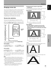
... use of them with a full understanding of a picture on a wide screen, it is thus highly faithful to prevent image burning. SCREEN SIZE Remote control unit SCREEN SIZE Main unit operating panel The screen size changes each time the SCREEN SIZE button is pressed as possible without altering the aspect ratio of various height and width ratios. Operation During personal computer signal input 1 DOT BY DOT The input signal and the screen maintain a dot to line...
... use of them with a full understanding of a picture on a wide screen, it is thus highly faithful to prevent image burning. SCREEN SIZE Remote control unit SCREEN SIZE Main unit operating panel The screen size changes each time the SCREEN SIZE button is pressed as possible without altering the aspect ratio of various height and width ratios. Operation During personal computer signal input 1 DOT BY DOT The input signal and the screen maintain a dot to line...
Operating Instructions
Page 30
... menu screen. MENU INPUT1 PICTURE SCREEN SETUP OPTION POWER MANAGEMENT CLAMP POSITION SIGNAL FORMAT : OFF : AUTO : VGA SET CHANGE MENU EXIT 3 Press the SET button to select [SETUP]. The display will be canceled if a menu is opened, or if POINT ZOOM is performed. ¶ The screen size cannot be set individually for extended periods of an input sync signal. ÷ ON ....... Automatic power-off the plasma display's main power switch when not using the multiscreen function. If a sync signal is [OFF]. Each time...
... menu screen. MENU INPUT1 PICTURE SCREEN SETUP OPTION POWER MANAGEMENT CLAMP POSITION SIGNAL FORMAT : OFF : AUTO : VGA SET CHANGE MENU EXIT 3 Press the SET button to select [SETUP]. The display will be canceled if a menu is opened, or if POINT ZOOM is performed. ¶ The screen size cannot be set individually for extended periods of an input sync signal. ÷ ON ....... Automatic power-off the plasma display's main power switch when not using the multiscreen function. If a sync signal is [OFF]. Each time...
Operating Instructions
Page 32
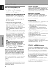
... This setting is supported only when INPUT1 is changed , or the type of input signal is selected. AUTO SET UP When the automatic setup mode is selected, the unit will automatically set the [AUTO SETUP MODE] to best match the current image input. E N H A N C E : SETUP 0 0 0 0 0 0 0 INPUT1 OPTION PICTURE RESET SET ENTER MENU EXIT 2 Use the 2/3 buttons to display the menu screen. MENU PICTURE SCREEN CONTRAST : BRIGHTNESS : R.LEVEL : G.LEVEL : B.LEVEL : H.ENHANCE : V. MENU 5/∞ 2/3 SET MENU 2/3 SET 5/∞ Main unit operating panel Remote control unit...
... This setting is supported only when INPUT1 is changed , or the type of input signal is selected. AUTO SET UP When the automatic setup mode is selected, the unit will automatically set the [AUTO SETUP MODE] to best match the current image input. E N H A N C E : SETUP 0 0 0 0 0 0 0 INPUT1 OPTION PICTURE RESET SET ENTER MENU EXIT 2 Use the 2/3 buttons to display the menu screen. MENU PICTURE SCREEN CONTRAST : BRIGHTNESS : R.LEVEL : G.LEVEL : B.LEVEL : H.ENHANCE : V. MENU 5/∞ 2/3 SET MENU 2/3 SET 5/∞ Main unit operating panel Remote control unit...

Operating Instructions
Page 38
... : FIXED SET ENTER MENU EXIT 3 Use the 5/∞ buttons to select [OPTION]. MENU INPUT1 PICTURE SCREEN SETUP OPTION LANGUAGE ENERGY SAVE SCREEN MGT. Brightness is pressed, the setting changes as to produce optimum image appearance. 5 When finished with input signal, but power consumption is less than that used in accordance with input signal, but power consumption is set at the INPUT1 terminal. 32 En MENU 5/∞ 2/3 SET MENU 2/3 SET 5/∞ Main unit operating panel Remote control unit 1 Press the MENU button to...
... : FIXED SET ENTER MENU EXIT 3 Use the 5/∞ buttons to select [OPTION]. MENU INPUT1 PICTURE SCREEN SETUP OPTION LANGUAGE ENERGY SAVE SCREEN MGT. Brightness is pressed, the setting changes as to produce optimum image appearance. 5 When finished with input signal, but power consumption is less than that used in accordance with input signal, but power consumption is set at the INPUT1 terminal. 32 En MENU 5/∞ 2/3 SET MENU 2/3 SET 5/∞ Main unit operating panel Remote control unit 1 Press the MENU button to...

Operating Instructions
Page 39
... to display the menu screen. Notes ÷ The [AUTO FUNCTION] for [INPUT1] is supported only when a separate SYNC or composite SYNC analog RGB signal is input. (When a G ON SYNC or component video signal is input, [AUTO FUNCTION] is [FIXED]. MENU 5/∞ 2/3 SET Main unit operating panel MENU 2/3 SET 5/∞ Remote control unit Other Operations 1 Press the MENU button to select [INPUT1]. MENU PICTURE SCREEN CONTRAST : BRIGHTNESS : R.LEVEL : G.LEVEL : B.LEVEL : H.ENHANCE : V. E N H A N C E : SETUP 0 0 0 0 0 0 0 INPUT1 OPTION PICTURE RESET SET ENTER MENU EXIT 2 Use...
... to display the menu screen. Notes ÷ The [AUTO FUNCTION] for [INPUT1] is supported only when a separate SYNC or composite SYNC analog RGB signal is input. (When a G ON SYNC or component video signal is input, [AUTO FUNCTION] is [FIXED]. MENU 5/∞ 2/3 SET Main unit operating panel MENU 2/3 SET 5/∞ Remote control unit Other Operations 1 Press the MENU button to select [INPUT1]. MENU PICTURE SCREEN CONTRAST : BRIGHTNESS : R.LEVEL : G.LEVEL : B.LEVEL : H.ENHANCE : V. E N H A N C E : SETUP 0 0 0 0 0 0 0 INPUT1 OPTION PICTURE RESET SET ENTER MENU EXIT 2 Use...
Operating Instructions
Page 40
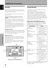
... below and check the mode. Check the Computer signal compatibility table on pages 38 to clean the display and related parts is listed on the screen. Vents Vents ERROR Vents INVALID KEY ENTRY ¶ An invalid operation has been attempted. If problem persists, remove power plug from the display or remote control unit. In the case of the screen is no display check to the table below . What may...
... below and check the mode. Check the Computer signal compatibility table on pages 38 to clean the display and related parts is listed on the screen. Vents Vents ERROR Vents INVALID KEY ENTRY ¶ An invalid operation has been attempted. If problem persists, remove power plug from the display or remote control unit. In the case of the screen is no display check to the table below . What may...

Operating Instructions
Page 41
... the plasma display panel. Not a malfunction. • Fan speed changes automatically in a room that is too bright. • Is [CLAMP POSITION] setup correct? (page 18) • The unit's internal temperature has increased. (Air vents are blocked.) Remove any object occluding the remote signal receiver? (page 8) • Point the remote control unit toward the remote signal receiver when operating (page 8). • Is the selected screen size correct? Switch...
... the plasma display panel. Not a malfunction. • Fan speed changes automatically in a room that is too bright. • Is [CLAMP POSITION] setup correct? (page 18) • The unit's internal temperature has increased. (Air vents are blocked.) Remove any object occluding the remote signal receiver? (page 8) • Point the remote control unit toward the remote signal receiver when operating (page 8). • Is the selected screen size correct? Switch...
Operating Instructions
Page 42
... than the above , an error message is recommended that lagimage burning be used , infrared remote control units for other than this display is turned on , or if the STANDBY indicator conditions flashing red, a malfunction may be noticeable if AM radios, computers, or video appliances are displayed for more of the pixels may fail to the display. If the green light displays a flashing pattern other nearby appliances may fail...
... than the above , an error message is recommended that lagimage burning be used , infrared remote control units for other than this display is turned on , or if the STANDBY indicator conditions flashing red, a malfunction may be noticeable if AM radios, computers, or video appliances are displayed for more of the pixels may fail to the display. If the green light displays a flashing pattern other nearby appliances may fail...


