User Manual
Page 7
... 6 Remote control unit 7 Connection panel (PDP-607CMX 9 Connection panel (PDP-507CMX 10 Connection panel (PDP-427CMX 11 Installation and Connections 12 Installation of the unit 12 Connection to a personal computer 14 Audio connections 15 Power cord connection 16 Attaching the ferrite cores 16 How to route cables 17 System Settings 18 Setting the onscreen display language 18 Settings after connections 19 Operation 20 Selecting input source 20 Adjusting sound volume 21 Muting the sound 21 Confirming current status 21 Changing screen size 22 Enlarging one part of...
... 6 Remote control unit 7 Connection panel (PDP-607CMX 9 Connection panel (PDP-507CMX 10 Connection panel (PDP-427CMX 11 Installation and Connections 12 Installation of the unit 12 Connection to a personal computer 14 Audio connections 15 Power cord connection 16 Attaching the ferrite cores 16 How to route cables 17 System Settings 18 Setting the onscreen display language 18 Settings after connections 19 Operation 20 Selecting input source 20 Adjusting sound volume 21 Muting the sound 21 Confirming current status 21 Changing screen size 22 Enlarging one part of...
User Manual
Page 8
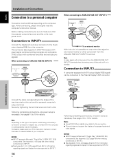
... allow the installation of cards for the connection of external devices, thus enhancing its expansion potential. ¶ Supports wide range of computer signals (analog/ digital) Supports non-compressed display of signals ranging from 640x400 and 640x480 (VGA) to 1024x768 (XGA), and compressed display of commercial use. ¶ Improved usability User convenience has been improved by Pioneer. Some of these include the one-touch screen adjustment, [AUTO SET UP...
... allow the installation of cards for the connection of external devices, thus enhancing its expansion potential. ¶ Supports wide range of computer signals (analog/ digital) Supports non-compressed display of signals ranging from 640x400 and 640x480 (VGA) to 1024x768 (XGA), and compressed display of commercial use. ¶ Improved usability User convenience has been improved by Pioneer. Some of these include the one-touch screen adjustment, [AUTO SET UP...
User Manual
Page 12
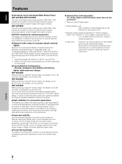
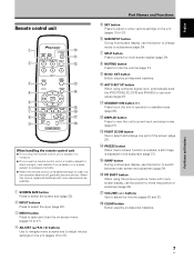
...). 7 DISPLAY/SET button Use to confirm onscreen menu selections, and to change the screen size. 0 VOL +/- (}/]) buttons When not indicated for use in onscreen menu items, these buttons are used to indicate error messages (page 41). 4 Handles Operation panel on the main unit 5 STANDBY/ON button ( ) Press to put the display in standby mode: The indicator lights red (page 20). VOL + 89 0 PDP-507CMX PDP-427CMX 1 STANDBY ON 23 PDP-607CMX 31 Main unit 1 Remote control sensor Point the remote control...
...). 7 DISPLAY/SET button Use to confirm onscreen menu selections, and to change the screen size. 0 VOL +/- (}/]) buttons When not indicated for use in onscreen menu items, these buttons are used to indicate error messages (page 41). 4 Handles Operation panel on the main unit 5 STANDBY/ON button ( ) Press to put the display in standby mode: The indicator lights red (page 20). VOL + 89 0 PDP-507CMX PDP-427CMX 1 STANDBY ON 23 PDP-607CMX 31 Main unit 1 Remote control sensor Point the remote control...
User Manual
Page 13
... or standby mode (page 20). = DISPLAY button Press to view the unit's current input and setup mode (page 21). ~ POINT ZOOM button Use to select and enlarge one part of subscreen (page 24). $ VOLUME (+/-) buttons Use to adjust the volume (pages 20 and 21). % CLEAR button Button used by professional installers. 7 En Part Names and Functions English SET button Button used by professional installers. 0 AUTO SET UP button When using the picture-in-picture mode with new ones as soon as possible. 1 SCREEN SIZE button Press...
... or standby mode (page 20). = DISPLAY button Press to view the unit's current input and setup mode (page 21). ~ POINT ZOOM button Use to select and enlarge one part of subscreen (page 24). $ VOLUME (+/-) buttons Use to adjust the volume (pages 20 and 21). % CLEAR button Button used by professional installers. 7 En Part Names and Functions English SET button Button used by professional installers. 0 AUTO SET UP button When using the picture-in-picture mode with new ones as soon as possible. 1 SCREEN SIZE button Press...
User Manual
Page 15
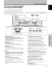
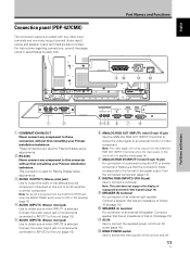
... sound is produced from the connected component (page 14). 0 DIGITAL RGB (INPUT2) (DVI-D jack) Use to switch the main power of copyguard-protected video signals (page 14). - AC IN Use to connect the supplied power cord to an AC outlet (page 16). = MAIN POWER switch Use to connect a computer. Audio input/ output and speaker output terminals are used for Plasma Display setup adjustments. 2 SPEAKER (R) terminal For connection of an external left speaker. English Connection panel (PDP-607CMX) The connection panel is selected. Note: This unit does not support...
... sound is produced from the connected component (page 14). 0 DIGITAL RGB (INPUT2) (DVI-D jack) Use to switch the main power of copyguard-protected video signals (page 14). - AC IN Use to connect the supplied power cord to an AC outlet (page 16). = MAIN POWER switch Use to connect a computer. Audio input/ output and speaker output terminals are used for Plasma Display setup adjustments. 2 SPEAKER (R) terminal For connection of an external left speaker. English Connection panel (PDP-607CMX) The connection panel is selected. Note: This unit does not support...
User Manual
Page 17
... is selected. Connect a speaker that the connection made corresponds to the format of the signal output from the AUDIO (OUTPUT) jack when the MAIN POWER switch is set to OFF or ON (standby) (page 15). 4 AUDIO (INPUT1) (Stereo mini jack) Use to obtain sound when INPUT1 is used for Plasma Display setup adjustments. 3 AUDIO (OUTPUT) (Stereo mini jack) Use to output the audio of an external right speaker. For instructions regarding connections, consult the pages noted in standby mode (page 14...
... is selected. Connect a speaker that the connection made corresponds to the format of the signal output from the AUDIO (OUTPUT) jack when the MAIN POWER switch is set to OFF or ON (standby) (page 15). 4 AUDIO (INPUT1) (Stereo mini jack) Use to obtain sound when INPUT1 is used for Plasma Display setup adjustments. 3 AUDIO (OUTPUT) (Stereo mini jack) Use to output the audio of an external right speaker. For instructions regarding connections, consult the pages noted in standby mode (page 14...
User Manual
Page 18
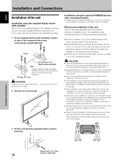
... Plasma Display by an installation specialist or the dealer where purchased. consult your dealer for a holes. Use commercially available M8 bolts that are shown in the accompanying illustration. ÷ Be sure to the side view diagram in the stands. If other than the thickness of the installation surface. 1 Fix the supplied stands to the installation surface at each of the 4 prepared holes using the supplied display stands (PDP-427CMX...
... Plasma Display by an installation specialist or the dealer where purchased. consult your dealer for a holes. Use commercially available M8 bolts that are shown in the accompanying illustration. ÷ Be sure to the side view diagram in the stands. If other than the thickness of the installation surface. 1 Fix the supplied stands to the installation surface at each of the 4 prepared holes using the supplied display stands (PDP-427CMX...
User Manual
Page 20
... Following completing connections, on the computer type. Note A video signal will not be sure to INPUT2. ¶ See Appendix 1-2/4, -4/4 (pages 44 and 47) for information regarding signals and display formats supported by tightening the terminal screws on -screen setup is necessary. NOTICE ¶ INPUT1 supports Microsoft "Plug & Play" (VESA DDC 1/2B) components. This connector also supports G ON SYNC (output with green signal combined with sync signal), and composite SYNC (output with DVI output (digital RGB signal) can...
... Following completing connections, on the computer type. Note A video signal will not be sure to INPUT2. ¶ See Appendix 1-2/4, -4/4 (pages 44 and 47) for information regarding signals and display formats supported by tightening the terminal screws on -screen setup is necessary. NOTICE ¶ INPUT1 supports Microsoft "Plug & Play" (VESA DDC 1/2B) components. This connector also supports G ON SYNC (output with green signal combined with sync signal), and composite SYNC (output with DVI output (digital RGB signal) can...
User Manual
Page 22
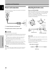
... Installation and Connections Power cord connection Connect the power cord after all component connections have been completed. AC IN 1 Attaching the ferrite cores Power cord (PDP-427CMX) Attach the accessory ferrite cores to this may cause fire or electric shock. If you use a power source converter plug, use a power supply voltage other than that the cord is necessary to disconnect power to prevent the ferrite core from its wall outlet. ÷ For the Plasma Display, use...
... Installation and Connections Power cord connection Connect the power cord after all component connections have been completed. AC IN 1 Attaching the ferrite cores Power cord (PDP-427CMX) Attach the accessory ferrite cores to this may cause fire or electric shock. If you use a power source converter plug, use a power supply voltage other than that the cord is necessary to disconnect power to prevent the ferrite core from its wall outlet. ÷ For the Plasma Display, use...
User Manual
Page 25
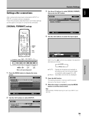
... [SIGNAL FORMAT] setting for each input (INPUT1 and INPUT2). 19 En MENU PICTURE SCREEN CONTRAST BRIGHTNESS H.ENHANCE V. English Settings after connections After components have been connected to INPUT1 or INPUT2, on-screen setup is completed, press the MENU button to exit the menu screen. System Settings MENU 2/3 SET 5/∞ Remote control unit STANDBY/ON DISPLAY MENU / SET INPUT SCREEN SIZE - Follow the procedure described below and make settings as follows: 3 AUTO Others 2 ÷ AUTO .... VOL + MENU SET 5/∞ 2/3 Main unit operating panel 1 Press the MENU button...
... [SIGNAL FORMAT] setting for each input (INPUT1 and INPUT2). 19 En MENU PICTURE SCREEN CONTRAST BRIGHTNESS H.ENHANCE V. English Settings after connections After components have been connected to INPUT1 or INPUT2, on-screen setup is completed, press the MENU button to exit the menu screen. System Settings MENU 2/3 SET 5/∞ Remote control unit STANDBY/ON DISPLAY MENU / SET INPUT SCREEN SIZE - Follow the procedure described below and make settings as follows: 3 AUTO Others 2 ÷ AUTO .... VOL + MENU SET 5/∞ 2/3 Main unit operating panel 1 Press the MENU button...
User Manual
Page 26
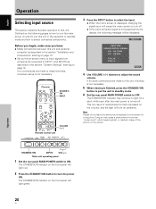
STANDBY/ ON INPUT VOLUME [+/-] Remote control unit STANDBY/ON DISPLAY MENU / SET INPUT SCREEN SIZE - FULL 4 Use VOLUME (+/-) buttons to ON. The STANDBY/ON indicator on page 18. Outlined on the following message will be displayed: INPUT1 CAUTION UNSUPPORTED SIGNAL FH: 86.7kHz FV: 88.5Hz - If no audio connections are made to this unit, this unit. Main unit operating panel 1 Set the rear panel MAIN POWER switch to adjust the sound volume. POL.H: - VOL + 3 Press the INPUT button to select the...
STANDBY/ ON INPUT VOLUME [+/-] Remote control unit STANDBY/ON DISPLAY MENU / SET INPUT SCREEN SIZE - FULL 4 Use VOLUME (+/-) buttons to ON. The STANDBY/ON indicator on page 18. Outlined on the following message will be displayed: INPUT1 CAUTION UNSUPPORTED SIGNAL FH: 86.7kHz FV: 88.5Hz - If no audio connections are made to this unit, this unit. Main unit operating panel 1 Set the rear panel MAIN POWER switch to adjust the sound volume. POL.H: - VOL + 3 Press the INPUT button to select the...
User Manual
Page 33
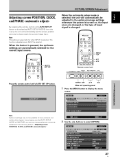
... operating panel 1 Press the MENU button to [INACTIVE], and use the manual adjustment methods explained in the following section, "Adjusting screen POSITION, CLOCK, and PHASE ". MENU PICTURE SCREEN LANGUAGE ENERGY SAVE TIMER SETTING S C R E E N M G T. Note This setting is supported only when INPUT1 is selected. MENU PICTURE SCREEN CONTRAST BRIGHTNESS H.ENHANCE V. AUTO SET UP PICTURE/SCREEN Adjustment When the automatic setup mode is changed , or the type of input signal is selected, the unit will automatically set the [AUTO SETUP MODE] to display the menu screen. In...
... operating panel 1 Press the MENU button to [INACTIVE], and use the manual adjustment methods explained in the following section, "Adjusting screen POSITION, CLOCK, and PHASE ". MENU PICTURE SCREEN LANGUAGE ENERGY SAVE TIMER SETTING S C R E E N M G T. Note This setting is supported only when INPUT1 is selected. MENU PICTURE SCREEN CONTRAST BRIGHTNESS H.ENHANCE V. AUTO SET UP PICTURE/SCREEN Adjustment When the automatic setup mode is changed , or the type of input signal is selected, the unit will automatically set the [AUTO SETUP MODE] to display the menu screen. In...
User Manual
Page 38
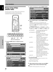
... image appearance. (PDP507CMX/PDP-427CMX) ÷ MODE1 Brightness is controlled in accordance with input signal, but power consumption is less than that used in [STANDARD] (STANDARD1, STANDARD2) mode. ÷ MODE2 Brightness is controlled in [MODE1]. ÷ MODE3 Brightness is set at fixed level, regardless of input signal level. MENU PICTURE SCREEN LANGUAGE ENERGY SAVE TIMER SETTING S C R E E N M G T. Each time the SET button is [STANDARD] (PDP607CMX/PDP-427CMX)/[STANDARD1] (PDP-507CMX). Note The [ENERGY SAVE] setting affects all input sources. The factory default setting...
... image appearance. (PDP507CMX/PDP-427CMX) ÷ MODE1 Brightness is controlled in accordance with input signal, but power consumption is less than that used in [STANDARD] (STANDARD1, STANDARD2) mode. ÷ MODE2 Brightness is controlled in [MODE1]. ÷ MODE3 Brightness is set at fixed level, regardless of input signal level. MENU PICTURE SCREEN LANGUAGE ENERGY SAVE TIMER SETTING S C R E E N M G T. Each time the SET button is [STANDARD] (PDP607CMX/PDP-427CMX)/[STANDARD1] (PDP-507CMX). Note The [ENERGY SAVE] setting affects all input sources. The factory default setting...
User Manual
Page 39
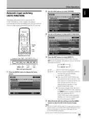
... + MENU SET 5/∞ 2/3 Main unit operating panel 1 Press the MENU button to select [AUTO FUNCTION]. AUTO SETUP MODE AUTO FUNCTION PIP DETECT SPLIT FREEZE SET ENTER INPUT1 SETUP OPTION :ENGLISH : S TA N D A R D :INACTIVE :OFF :ACTIVE :OFF MENU EXIT 3 Use the 5/∞ buttons to display the menu screen. MENU 2/3 SET 5/∞ Remote control unit STANDBY/ON DISPLAY MENU / SET INPUT SCREEN SIZE - When enabled, the selector automatically switches the display's input source to INPUT1 when an image signal is detected at INPUT1, the input source automatically switches to...
... + MENU SET 5/∞ 2/3 Main unit operating panel 1 Press the MENU button to select [AUTO FUNCTION]. AUTO SETUP MODE AUTO FUNCTION PIP DETECT SPLIT FREEZE SET ENTER INPUT1 SETUP OPTION :ENGLISH : S TA N D A R D :INACTIVE :OFF :ACTIVE :OFF MENU EXIT 3 Use the 5/∞ buttons to display the menu screen. MENU 2/3 SET 5/∞ Remote control unit STANDBY/ON DISPLAY MENU / SET INPUT SCREEN SIZE - When enabled, the selector automatically switches the display's input source to INPUT1 when an image signal is detected at INPUT1, the input source automatically switches to...
User Manual
Page 41
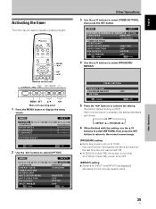
... SET CHANGE MENU EXIT 5 Press the 2/3 buttons to select [TIMER SETTING], then press the SET button. Input and function settings are displayed alternately for INPUT1 and INPUT2 are the same as follows: 3 OFF REPEAT 2 PROGRAM 2 6 When finished with the setting, use the 5/∞ buttons to select [RETURN], then press the SET button to return to the normal screen image. [PROGRAM] setting ÷ Every day, power turns on at 10:00. MENU 2/3 SET 5/∞ Remote control unit STANDBY/ON DISPLAY MENU / SET INPUT SCREEN SIZE - AUTO SETUP MODE AUTO...
... SET CHANGE MENU EXIT 5 Press the 2/3 buttons to select [TIMER SETTING], then press the SET button. Input and function settings are displayed alternately for INPUT1 and INPUT2 are the same as follows: 3 OFF REPEAT 2 PROGRAM 2 6 When finished with the setting, use the 5/∞ buttons to select [RETURN], then press the SET button to return to the normal screen image. [PROGRAM] setting ÷ Every day, power turns on at 10:00. MENU 2/3 SET 5/∞ Remote control unit STANDBY/ON DISPLAY MENU / SET INPUT SCREEN SIZE - AUTO SETUP MODE AUTO...
User Manual
Page 42
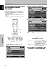
... :OFF MENU EXIT 3 Use the 5/∞ buttons to activate the setting. The factory default setting is detected during side-byside display. ÷ The lack of the subscreen are automatically turned off. Other Operations 36 En MENU PICTURE SCREEN LANGUAGE ENERGY SAVE TIMER SETTING S C R E E N M G T. AUTO SETUP MODE AUTO FUNCTION PIP DETECT SPLIT FREEZE SET CHANGE INPUT1 SETUP OPTION :ENGLISH : S TA N D A R D :INACTIVE :OFF :ACTIVE :OFF MENU EXIT 4 Press the SET button to select [PIP DETECT]. Each time the button is...
... :OFF MENU EXIT 3 Use the 5/∞ buttons to activate the setting. The factory default setting is detected during side-byside display. ÷ The lack of the subscreen are automatically turned off. Other Operations 36 En MENU PICTURE SCREEN LANGUAGE ENERGY SAVE TIMER SETTING S C R E E N M G T. AUTO SETUP MODE AUTO FUNCTION PIP DETECT SPLIT FREEZE SET CHANGE INPUT1 SETUP OPTION :ENGLISH : S TA N D A R D :INACTIVE :OFF :ACTIVE :OFF MENU EXIT 4 Press the SET button to select [PIP DETECT]. Each time the button is...

User Manual
Page 46
... [PICTURE] setting correct? (page 26) Problems commonly mistaken as breakdown Problem • The screen is displayed in a room that is too bright. • The unit's internal temperature has increased. (Air vents are blocked.) Remove any object occluding the remote signal receiver? (page 8) • Point the remote control unit toward the remote signal receiver when operating (page 8). • Is the selected screen size correct? Consult with your installation technician. Switch...
... [PICTURE] setting correct? (page 26) Problems commonly mistaken as breakdown Problem • The screen is displayed in a room that is too bright. • The unit's internal temperature has increased. (Air vents are blocked.) Remove any object occluding the remote signal receiver? (page 8) • Point the remote control unit toward the remote signal receiver when operating (page 8). • Is the selected screen size correct? Consult with your installation technician. Switch...
Brochure
Page 3
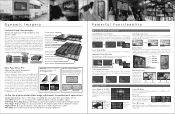
... PUMP j ai Or, 3 rint5um, Powerful Functional ity Dual ree nction Standard Dual Screen Mode IR remote and RS-232C control operations permit the use of Old and New Cell Structure (Greater Light Volume) I Plasma Mahar. P-in-P is also significantly higher, meaning that even high-resolution signals are normally cut off. •Color-Off: Removes color information for display calibration. MID HIGH 3. Auto ID Setting Without ABL With ABL...
... PUMP j ai Or, 3 rint5um, Powerful Functional ity Dual ree nction Standard Dual Screen Mode IR remote and RS-232C control operations permit the use of Old and New Cell Structure (Greater Light Volume) I Plasma Mahar. P-in-P is also significantly higher, meaning that even high-resolution signals are normally cut off. •Color-Off: Removes color information for display calibration. MID HIGH 3. Auto ID Setting Without ABL With ABL...
Brochure
Page 4
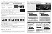
... M HcDBSriDdeITM Allows the PDP to connect directly to further lowering power consumption: Power Save, Intermediate, Linear Brightness (which decreases the peak intensity of high-brightness images), Auto Brightness Control (which automatically adjusts panel brightness depending upon room lighting), and Video Mute (which temporarily turns off information • Input signal information • Cause of error AMX DuetTM Program Support The PDP-427CMX makes use of analog or digital signals, with G on Sync) Component Video Signal LeveVimpedance Y: 1 Vp...
... M HcDBSriDdeITM Allows the PDP to connect directly to further lowering power consumption: Power Save, Intermediate, Linear Brightness (which decreases the peak intensity of high-brightness images), Auto Brightness Control (which automatically adjusts panel brightness depending upon room lighting), and Video Mute (which temporarily turns off information • Input signal information • Cause of error AMX DuetTM Program Support The PDP-427CMX makes use of analog or digital signals, with G on Sync) Component Video Signal LeveVimpedance Y: 1 Vp...
Brochure
Page 5
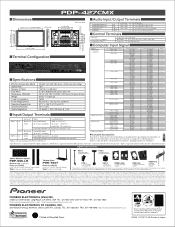
... extended periods of time, or use either of these screen modes to 16 018 W +8 W(6 S2) RS-232C (for Power Code) x 2, Cable Ties x 2, Display Stands x 2, 1, Washers x 2, Hex Hole Bolts x 2, Remote Control Unit Holder x 1, Operating Instructions x Warranty x 1 "Apple Macintosh is a registered trademark of time may cause image retention. Optional Accessories PSA-1 ADJUSTABLE HEIGHT SUSPENSION ADAPTER PSA-2 ADJUSTABLE HEIGHT SUSPENSION ADAPTER Ii1■ Optional Side-Mount Speakers PDP-S56-LR Maximum Input 30 W/8 ohms Dimensions (WxHxD) 3-17...
... extended periods of time, or use either of these screen modes to 16 018 W +8 W(6 S2) RS-232C (for Power Code) x 2, Cable Ties x 2, Display Stands x 2, 1, Washers x 2, Hex Hole Bolts x 2, Remote Control Unit Holder x 1, Operating Instructions x Warranty x 1 "Apple Macintosh is a registered trademark of time may cause image retention. Optional Accessories PSA-1 ADJUSTABLE HEIGHT SUSPENSION ADAPTER PSA-2 ADJUSTABLE HEIGHT SUSPENSION ADAPTER Ii1■ Optional Side-Mount Speakers PDP-S56-LR Maximum Input 30 W/8 ohms Dimensions (WxHxD) 3-17...


