Service Manual
Page 1
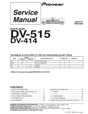
... 1 KC - SCHEMATIC DIAGRAM 12 4. • DV-515 STANDBY POWER OFF ON VIRTUAL DOLBY SURROND 10 KEY OPERATION TITLE +10 1 2 3 4 5 6 7 8 9 0 0 FL OFF 4 1 ¡ ¢ 7 £¥8 DVD PLAYER DV-515 DV-414 ORDER NO. AC120V 1 • Refer to the service guide RRV2004 for DV-515. PCB PARTS LIST 39 6. PANEL FACILITIES AND SPECIFICATIONS .... 52 PIONEER ELECTRONIC CORPORATION 4-1, Meguro 1-Chome, Meguro-ku, Tokyo 153-8654, Japan PIONEER ELECTRONICS SERVICE, INC. PCB CONNECTION DIAGRAM 29 5. ADJUSTMENT 44 7. Box 1760...
... 1 KC - SCHEMATIC DIAGRAM 12 4. • DV-515 STANDBY POWER OFF ON VIRTUAL DOLBY SURROND 10 KEY OPERATION TITLE +10 1 2 3 4 5 6 7 8 9 0 0 FL OFF 4 1 ¡ ¢ 7 £¥8 DVD PLAYER DV-515 DV-414 ORDER NO. AC120V 1 • Refer to the service guide RRV2004 for DV-515. PCB PARTS LIST 39 6. PANEL FACILITIES AND SPECIFICATIONS .... 52 PIONEER ELECTRONIC CORPORATION 4-1, Meguro 1-Chome, Meguro-ku, Tokyo 153-8654, Japan PIONEER ELECTRONICS SERVICE, INC. PCB CONNECTION DIAGRAM 29 5. ADJUSTMENT 44 7. Box 1760...
Service Manual
Page 2
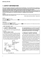
... additional copies of identical designation. (slow operating fuse) on the parts list in this Service Manual, may be obtained by them necessarily can adversely affect the safety and reliability of the appliance (input/output terminals, screwheads, metal overlays, control shaft, etc.). Replacement parts which are identified by this Service Manual. DV-515, DV-414 1. it is intended for the casual do so and refer the repair to...
... additional copies of identical designation. (slow operating fuse) on the parts list in this Service Manual, may be obtained by them necessarily can adversely affect the safety and reliability of the appliance (input/output terminals, screwheads, metal overlays, control shaft, etc.). Replacement parts which are identified by this Service Manual. DV-515, DV-414 1. it is intended for the casual do so and refer the repair to...
Service Manual
Page 3
...; : Refer to the service guide RRV2004. 2. Therefore, when replacing, be sure to use parts of identical designation. • Screws adjacent to mark on some component parts indicates the importance of the safety factor of IC101 is shorted to +5V in the DVDM assy. SERVICING OPERATION OF THE APPARATUS SHOULD BE DONE BY A SPECIALLY INSTRUCTED PERSON. Inside detection switch (S201 on the...
...; : Refer to the service guide RRV2004. 2. Therefore, when replacing, be sure to use parts of identical designation. • Screws adjacent to mark on some component parts indicates the importance of the safety factor of IC101 is shorted to +5V in the DVDM assy. SERVICING OPERATION OF THE APPARATUS SHOULD BE DONE BY A SPECIALLY INSTRUCTED PERSON. Inside detection switch (S201 on the...
Service Manual
Page 4
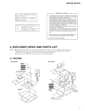
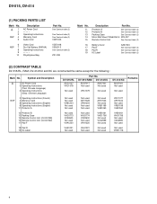
DV-515, DV-414 (1) PACKING PARTS LIST Mark No. 1 2 3 NSP 4 5 Description AC Power Cord Operating Instructions Warranty Card Audio Cord 6 NSP 7 8 9 10 Video Cord Dry Cell Battery (R6P,AA) Operating Instructions Polyethylene Bag Part No. Symbol and Description 1 AC Power Cord 3 Operating Instructions (Trad. See Contrast table (2) See Contrast table (2) See Contrast table (2) VDE1033 VDE1048 VEM-013 See Contrast table (2) Z21-038 Mark No. 11 12 13 14 15 Description Part No. Chinese Language) DV-515...
DV-515, DV-414 (1) PACKING PARTS LIST Mark No. 1 2 3 NSP 4 5 Description AC Power Cord Operating Instructions Warranty Card Audio Cord 6 NSP 7 8 9 10 Video Cord Dry Cell Battery (R6P,AA) Operating Instructions Polyethylene Bag Part No. Symbol and Description 1 AC Power Cord 3 Operating Instructions (Trad. See Contrast table (2) See Contrast table (2) See Contrast table (2) VDE1033 VDE1048 VEM-013 See Contrast table (2) Z21-038 Mark No. 11 12 13 14 15 Description Part No. Chinese Language) DV-515...

Service Manual
Page 5
... except for the following : Mark No. Symbol and Description 1 Bonnet Case S 2 Tray Panel 4 POWER Button 5 PW Button Joint 6 Tray DV-515/RL VXX2615 VNK4310 VNK4159 VNK4179 VNK4333 Part No. DV-515/RAM DV-414/KU VXX2615 VNK4310 Not used Not used VNK4333 VXX2612 VNK4316 Not used Not used VNL1731 DV-414/KC VXX2612 VNK4316 Not used Not used VNL1731 Remarks 11 Screw 17 65 Label BCZ40P060FNI BCZ40P060FNI BCZ40P060FZK BCZ40P060FZK...
... except for the following : Mark No. Symbol and Description 1 Bonnet Case S 2 Tray Panel 4 POWER Button 5 PW Button Joint 6 Tray DV-515/RL VXX2615 VNK4310 VNK4159 VNK4179 VNK4333 Part No. DV-515/RAM DV-414/KU VXX2615 VNK4310 Not used Not used VNK4333 VXX2612 VNK4316 Not used Not used VNL1731 DV-414/KC VXX2612 VNK4316 Not used Not used VNL1731 Remarks 11 Screw 17 65 Label BCZ40P060FNI BCZ40P060FNI BCZ40P060FZK BCZ40P060FZK...

Service Manual
Page 6
... 6 DV-515, DV-414 2.3 FRONT PANEL SECTION 13 16 DV-515/RAM, DV-414/KU, KC only 12(3/4) 14 12(2/4) 5 12(1/4) 4 6 15 DV-515 7 only 16 DV-515 only 12(4/4) 10 3 9 11 8 2 (1) FRONT PANEL SECTION PARTS LIST Mark No. Description Part No. 1 Front Panel 2 FL Lens 3 Name Plate 4 LED Lens 5 PW Button See Contrast table (2) See Contrast table (2) See Contrast table (2) PNW2019 See Contrast table (2) 6 PLAY...
... 6 DV-515, DV-414 2.3 FRONT PANEL SECTION 13 16 DV-515/RAM, DV-414/KU, KC only 12(3/4) 14 12(2/4) 5 12(1/4) 4 6 15 DV-515 7 only 16 DV-515 only 12(4/4) 10 3 9 11 8 2 (1) FRONT PANEL SECTION PARTS LIST Mark No. Description Part No. 1 Front Panel 2 FL Lens 3 Name Plate 4 LED Lens 5 PW Button See Contrast table (2) See Contrast table (2) See Contrast table (2) PNW2019 See Contrast table (2) 6 PLAY...

Service Manual
Page 8
...used Not used DV-414/KC VNA1981 VWR1305 VWV1615 VNA1990 Not used Not used Remarks 8 DVDM CN9020) Flexible Cable (14P) VDA1697 (AVJB CN202 - DVDM CN110) 19 20 NSP 21 Flexible Cable (26P) VDA1695 (AVJB CN101 - Flexible Cable (12P) VDA1693 (LOSB CN305 - DVDM CN602) Flexible Cable (26P) VDA1689 (POWER SUPPLY CN103 - DV-515, DV-414 (1) BOTTOM VIEW SECTION PARTS LIST... 10 POWER SUPPLY Assy PCB Holder Flat Cable Clip Cord Stopper PCB Holder See Contrast table (2) PNW2100 VEC2018 ZCB-069Z VNE2122 11 12 13 NSP 14 15 DVDM Assy AVJB Assy Rear Panel Loading Mechanism ...
...used Not used DV-414/KC VNA1981 VWR1305 VWV1615 VNA1990 Not used Not used Remarks 8 DVDM CN9020) Flexible Cable (14P) VDA1697 (AVJB CN202 - DVDM CN110) 19 20 NSP 21 Flexible Cable (26P) VDA1695 (AVJB CN101 - Flexible Cable (12P) VDA1693 (LOSB CN305 - DVDM CN602) Flexible Cable (26P) VDA1689 (POWER SUPPLY CN103 - DV-515, DV-414 (1) BOTTOM VIEW SECTION PARTS LIST... 10 POWER SUPPLY Assy PCB Holder Flat Cable Clip Cord Stopper PCB Holder See Contrast table (2) PNW2100 VEC2018 ZCB-069Z VNE2122 11 12 13 NSP 14 15 DVDM Assy AVJB Assy Rear Panel Loading Mechanism ...

Service Manual
Page 28
...output when selecting color difference output) V: 500mV/div. GND 15 IC801-pin 45 (CB output when selecting color difference output) V: 500mV/div. H: 0.2µS/div. H: 10µS/div. 5 IC201-pin 39 (EFM before slice) V: 1V/div. DC1.4V 12 IC801-pin 45 (Composite video output) V: 500mV/div. H: 10µS/div. 4 TP (Tracking Error... of R264 (RPWM) GND 17 IC801-pin 36 (CR output when selecting color difference output) V: 500mV/div. DV-515, DV-414 • WAVEFORMS OF DVDM ASSY Note : The encircled numbers denote measuring point in the schematic diagram. H: 0.2µS/div.
...output when selecting color difference output) V: 500mV/div. GND 15 IC801-pin 45 (CB output when selecting color difference output) V: 500mV/div. H: 0.2µS/div. H: 10µS/div. 5 IC201-pin 39 (EFM before slice) V: 1V/div. DC1.4V 12 IC801-pin 45 (Composite video output) V: 500mV/div. H: 10µS/div. 4 TP (Tracking Error... of R264 (RPWM) GND 17 IC801-pin 36 (CR output when selecting color difference output) V: 500mV/div. DV-515, DV-414 • WAVEFORMS OF DVDM ASSY Note : The encircled numbers denote measuring point in the schematic diagram. H: 0.2µS/div.

Service Manual
Page 29
... include all necessary parts for respective destinations, be sure to check with resistor DGS D G SD G S Field effect transistor A 3. For further information for several destinations. Part numbers in PCB diagrams match those in the schematic diagrams. 2. Symbol In PCB Diagrams Symbol In Schematic Diagrams B C EB C E Part Name BCE Transistor BCE B C EB C E Transistor with the schematic diagram. 4. 1 2 3 4 DV-515, DV-414 4. View point of PCB and schematic diagrams is shown...
... include all necessary parts for respective destinations, be sure to check with resistor DGS D G SD G S Field effect transistor A 3. For further information for several destinations. Part numbers in PCB diagrams match those in the schematic diagrams. 2. Symbol In PCB Diagrams Symbol In Schematic Diagrams B C EB C E Part Name BCE Transistor BCE B C EB C E Transistor with the schematic diagram. 4. 1 2 3 4 DV-515, DV-414 4. View point of PCB and schematic diagrams is shown...

Service Manual
Page 46
... clock output with system controller I/O Communication data output with system controller I Communication data input with I system controller H: Communication permission I Not used 40 P33 P33 I Remote control signal input −- GENERAL INFORMATION 7.1 PARTS 7.1.1 IC • The information shown in the schematic diagrams. • List of IC PE5018B, PE5012A, PD3381A PE5018B (FLKY ASSY : IC101) • FL Control IC • Pin Function No. O Non connection O FL OFF LED ON/OFF L: ON O Virtual Dolby Surround...
... clock output with system controller I/O Communication data output with system controller I Communication data input with I system controller H: Communication permission I Not used 40 P33 P33 I Remote control signal input −- GENERAL INFORMATION 7.1 PARTS 7.1.1 IC • The information shown in the schematic diagrams. • List of IC PE5018B, PE5012A, PD3381A PE5018B (FLKY ASSY : IC101) • FL Control IC • Pin Function No. O Non connection O FL OFF LED ON/OFF L: ON O Virtual Dolby Surround...

Service Manual
Page 47
... adjustment C 47 DV-515, DV-414 PE5012A (DVDM ASSY : IC501) • Mechanism Control IC • Pin Function No. Pin Name 1 LODDRV 2 XDF INH 3 FOFST3 I/O Function I/O Loading motor drive output I/O High impedance (input) at DEFECT ON "L" output at DEFECT OFF O Not used I /O Function O DSP parallel command setting output "L" O Address strobe of subcode Q O CPU read pulse "L" O CPU write pulse "L" No. input (H: S0+S1 period) INT T HOLD INT DSP auto sequence busy input...
... adjustment C 47 DV-515, DV-414 PE5012A (DVDM ASSY : IC501) • Mechanism Control IC • Pin Function No. Pin Name 1 LODDRV 2 XDF INH 3 FOFST3 I/O Function I/O Loading motor drive output I/O High impedance (input) at DEFECT ON "L" output at DEFECT OFF O Not used I /O Function O DSP parallel command setting output "L" O Address strobe of subcode Q O CPU read pulse "L" O CPU write pulse "L" No. input (H: S0+S1 period) INT T HOLD INT DSP auto sequence busy input...

Service Manual
Page 49
... I/O Function I MD1, MD0 = 10 internal ROM I GND − V+5D − V+5D − V+5D − V+5D I Rear panel switch H/M/L = NTSC/Auto/PAL I Authoring emulator mode setting I (YAKU) special mode setting I Reception error (unlock signal) input of external digital input (S9) I C2 error correction impossible pulse I Dolby virtual chip reset & pulse (DV-515 only) − GND I Serial bus data input O Serial bus data output I RS-232C RxD I RS-232C TxD I/O Serial bus clock input and output I Block sync. DV-515, DV-414 No...
... I/O Function I MD1, MD0 = 10 internal ROM I GND − V+5D − V+5D − V+5D − V+5D I Rear panel switch H/M/L = NTSC/Auto/PAL I Authoring emulator mode setting I (YAKU) special mode setting I Reception error (unlock signal) input of external digital input (S9) I C2 error correction impossible pulse I Dolby virtual chip reset & pulse (DV-515 only) − GND I Serial bus data input O Serial bus data output I RS-232C RxD I RS-232C TxD I/O Serial bus clock input and output I Block sync. DV-515, DV-414 No...
Service Manual
Page 52
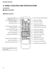
PANEL FACILITIES AND SPECIFICATIONS 8.1 DV-515 PANEL FACILITIES 7 Remote control Subtitle button (SUBTITLE) STANDBY/ON button ( ) Audio switching button (AUDIO) Mode button (MODE) Title button (TITLE) Previous button (PREV 4) Play button (PLAY 3) Fast reverse button (REV 1) Stop button (STOP 7) Pause button (PAUSE 8) Program button (PROGRAM) Chapter/time button (CHP/TIME) Repeat button (REPEAT) Repeat A-B button (REPEAT A-B) OPEN/ CLOSE 0 AUDIO SUBTITLE ANGLE MODE TITLE MENU 5 DISPLAY RETURN 2 ENTER 3 PREV NEXT 4 ∞ ¢ REV 1 PLAY 3 FWD ¡ PAUSE 8 STOP 7 1 2 ...
PANEL FACILITIES AND SPECIFICATIONS 8.1 DV-515 PANEL FACILITIES 7 Remote control Subtitle button (SUBTITLE) STANDBY/ON button ( ) Audio switching button (AUDIO) Mode button (MODE) Title button (TITLE) Previous button (PREV 4) Play button (PLAY 3) Fast reverse button (REV 1) Stop button (STOP 7) Pause button (PAUSE 8) Program button (PROGRAM) Chapter/time button (CHP/TIME) Repeat button (REPEAT) Repeat A-B button (REPEAT A-B) OPEN/ CLOSE 0 AUDIO SUBTITLE ANGLE MODE TITLE MENU 5 DISPLAY RETURN 2 ENTER 3 PREV NEXT 4 ∞ ¢ REV 1 PLAY 3 FWD ¡ PAUSE 8 STOP 7 1 2 ...
Service Manual
Page 53
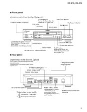
... you can simultaneously connect. Power cord connection terminal 53 S-Video output jack* Video output jack* Control input jack Component video output jacks** DIGITAL OUT OPT. Play/Pause 6 button TITLE button +10 button Remote sensor Stop 7 button STANDBY POWER OFF ON VIRTUAL DOLBY SURROND 10 KEY OPERATION TITLE +10 1 2 3 4 5 6 7 8 9 0 0 FL OFF 4 1 ¡ ¢ 7 £¥8 STANDBY/ON switch (Flat blade 2-pin AC plug model) Power switch (Round blade 2-pin AC plug model) Number buttons Display window VIRTUAL DOLBY SURROUND button 7 Rear panel Forward ¡ ¢...
... you can simultaneously connect. Power cord connection terminal 53 S-Video output jack* Video output jack* Control input jack Component video output jacks** DIGITAL OUT OPT. Play/Pause 6 button TITLE button +10 button Remote sensor Stop 7 button STANDBY POWER OFF ON VIRTUAL DOLBY SURROND 10 KEY OPERATION TITLE +10 1 2 3 4 5 6 7 8 9 0 0 FL OFF 4 1 ¡ ¢ 7 £¥8 STANDBY/ON switch (Flat blade 2-pin AC plug model) Power switch (Round blade 2-pin AC plug model) Number buttons Display window VIRTUAL DOLBY SURROUND button 7 Rear panel Forward ¡ ¢...

Service Manual
Page 54
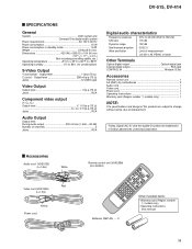
... Last Memory is in memory. Indicates Multi-Angle playback is being recorded in progress. Indicates Dolby digital playback Indicates that a title is being displayed 96 kHz TITLE GUI ANGLE LAST MEMO CONDITION DOLBY CHP/TRK REMAIN TOTAL DIGITAL Indicates that playback settings (condition) have been memorized. Indicates total playback time of 96 kHz. DV-515, DV-414 7 Display window Indicates GUI operation is being displayed Indicates the playback mode, title, type of disc, etc.
... Last Memory is in memory. Indicates Multi-Angle playback is being recorded in progress. Indicates Dolby digital playback Indicates that a title is being displayed 96 kHz TITLE GUI ANGLE LAST MEMO CONDITION DOLBY CHP/TRK REMAIN TOTAL DIGITAL Indicates that playback settings (condition) have been memorized. Indicates total playback time of 96 kHz. DV-515, DV-414 7 Display window Indicates GUI operation is being displayed Indicates the playback mode, title, type of disc, etc.
Service Manual
Page 55
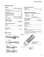
... Audio Output (2 pairs) Output level During audio output 200 mVrms (1 kHz, -20 dB) Number of the two power cords above is supplied.) Other included items : • Operating instructions (this product are trademarks of this manual) 55 PEAK) or lower Other Terminals Optical digital output Optical digital jack Coaxial digital output RCA jack CONTROL IN Minijack (3.5ø) Accessories Remote control unit 1 AA (R6P) dry cell batteries 2 Audio cord 1 Video cord 1 Power cord 1 Operating Instructions 1 NOTE: The specifications and design of Dolby...
... Audio Output (2 pairs) Output level During audio output 200 mVrms (1 kHz, -20 dB) Number of the two power cords above is supplied.) Other included items : • Operating instructions (this product are trademarks of this manual) 55 PEAK) or lower Other Terminals Optical digital output Optical digital jack Coaxial digital output RCA jack CONTROL IN Minijack (3.5ø) Accessories Remote control unit 1 AA (R6P) dry cell batteries 2 Audio cord 1 Video cord 1 Power cord 1 Operating Instructions 1 NOTE: The specifications and design of Dolby...
Service Manual
Page 56
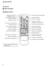
DV-515, DV-414 8.2 DV-414 PANEL FACILITIES 7 Remote control Subtitle button (SUBTITLE) STANDBY/ON button ( ) Audio switching button (AUDIO) Mode button (MODE) Title button (TITLE) Previous button (PREV 4) Play button (PLAY 3) Fast reverse button (REV 1) Stop button (STOP 7) Pause button (PAUSE 8) Program button (PROGRAM) Chapter/time button (CHP/TIME) Repeat button (REPEAT) Repeat A-B button (REPEAT A-B) OPEN/ CLOSE 0 AUDIO SUBTITLE ANGLE MODE TITLE MENU 5 DISPLAY RETURN 2 ENTER 3 PREV NEXT 4 ∞ ¢ REV 1 PLAY 3 FWD ¡ PAUSE 8 STOP 7 1 2 STEP e E CLEAR 3 C...
DV-515, DV-414 8.2 DV-414 PANEL FACILITIES 7 Remote control Subtitle button (SUBTITLE) STANDBY/ON button ( ) Audio switching button (AUDIO) Mode button (MODE) Title button (TITLE) Previous button (PREV 4) Play button (PLAY 3) Fast reverse button (REV 1) Stop button (STOP 7) Pause button (PAUSE 8) Program button (PROGRAM) Chapter/time button (CHP/TIME) Repeat button (REPEAT) Repeat A-B button (REPEAT A-B) OPEN/ CLOSE 0 AUDIO SUBTITLE ANGLE MODE TITLE MENU 5 DISPLAY RETURN 2 ENTER 3 PREV NEXT 4 ∞ ¢ REV 1 PLAY 3 FWD ¡ PAUSE 8 STOP 7 1 2 STEP e E CLEAR 3 C...
Service Manual
Page 57
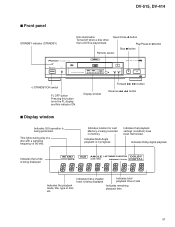
... the playback mode, title, type of disc, etc. Indicates Dolby digital playback Indicates that a chapter/ track is being displayed Indicates total playback time of 96 kHz. This lights during play of a disc with a sampling frequency of side Indicates remaining playback time 57 Indicates that playback settings (condition) have been memorized. DV-515, DV-414 7 Front panel STANDBY indicator (STANDBY) Disc illumination Turned off when a disc other than a DVD is in memory. Open/Close 0 button Play/Pause 6 button Stop 7 button Remote sensor STANDBY STANDBY/ON DVD PLAYER Û...
... the playback mode, title, type of disc, etc. Indicates Dolby digital playback Indicates that a chapter/ track is being displayed Indicates total playback time of 96 kHz. This lights during play of a disc with a sampling frequency of side Indicates remaining playback time 57 Indicates that playback settings (condition) have been memorized. DV-515, DV-414 7 Front panel STANDBY indicator (STANDBY) Disc illumination Turned off when a disc other than a DVD is in memory. Open/Close 0 button Play/Pause 6 button Stop 7 button Remote sensor STANDBY STANDBY/ON DVD PLAYER Û...

Service Manual
Page 58
... Set digital output to view NTSC disc because the picture may roll. If the TV has a V-Hold control, adjust it is caused by the NTSC = PAL conversion. 58 Video output changes as is. DV-515, DV-414 7 Rear panel Digital Output Jacks (Coaxial, Optical) This is used for output of TV SYSTEM switch NTSC PAL AUTO NTSC MOD. Type Disc Format Video CD NTSC PAL DVD NTSC PAL CD, No disc Stop mode Output format Position of the digital audio signal recorded on Video CDs. 2. S-Video output jack* Video output jack* Control input jack Component video output jacks** DIGITAL...
... Set digital output to view NTSC disc because the picture may roll. If the TV has a V-Hold control, adjust it is caused by the NTSC = PAL conversion. 58 Video output changes as is. DV-515, DV-414 7 Rear panel Digital Output Jacks (Coaxial, Optical) This is used for output of TV SYSTEM switch NTSC PAL AUTO NTSC MOD. Type Disc Format Video CD NTSC PAL DVD NTSC PAL CD, No disc Stop mode Output format Position of the digital audio signal recorded on Video CDs. 2. S-Video output jack* Video output jack* Control input jack Component video output jacks** DIGITAL...
Service Manual
Page 59
... humidity 5% to improvement. Output level 1 Vp-p (75 Ω ) C (color) - "Dolby, Digital (AC-3)" and the double-D symbol are subject to change without notice, due to 85% (no condensation) S-Video Output Y (luminance) - PEAK) or lower Other Terminals Optical digital output Optical digital jack Coaxial digital output RCA jack CONTROL IN Minijack (3.5ø) Accessories Remote control unit 1 AA (R6P) dry cell batteries 2 Audio cord 1 Video cord 1 Power cord 1 Operating Instructions 1 Warranty card (Region number 1 models only 1 NOTE: The specifications and design of...
... humidity 5% to improvement. Output level 1 Vp-p (75 Ω ) C (color) - "Dolby, Digital (AC-3)" and the double-D symbol are subject to change without notice, due to 85% (no condensation) S-Video Output Y (luminance) - PEAK) or lower Other Terminals Optical digital output Optical digital jack Coaxial digital output RCA jack CONTROL IN Minijack (3.5ø) Accessories Remote control unit 1 AA (R6P) dry cell batteries 2 Audio cord 1 Video cord 1 Power cord 1 Operating Instructions 1 Warranty card (Region number 1 models only 1 NOTE: The specifications and design of...


