Service Manual
Page 1
... MODEL(S) AND TYPE(S). ZZE APR. 2002 Printed in Japan STANDBY/ON 1¡ 4¢ 7 8 OPEN/ CLOSE 0 3 Î DV-353-K DVD PLAYER DV-353-K DV-353-S DV-250 DV-251 ORDER NO. PIONEER CORPORATION 4-1, Meguro 1-chome, Meguro-ku, Tokyo 153-8654, Japan PIONEER ELECTRONICS (USA) INC. LTD. 253 Alexandra Road, #04-01, Singapore 159936 PIONEER CORPORATION 2002 T - Model Type Power Requirement Regional restriction codes (Region No.) DV-353-K KUXJ AC120V 1 DV-353-K KCXJ AC120V 1 DV-353-S KUXU/CA AC120V 1 DV-250 KUXU AC120V 1 DV...
... MODEL(S) AND TYPE(S). ZZE APR. 2002 Printed in Japan STANDBY/ON 1¡ 4¢ 7 8 OPEN/ CLOSE 0 3 Î DV-353-K DVD PLAYER DV-353-K DV-353-S DV-250 DV-251 ORDER NO. PIONEER CORPORATION 4-1, Meguro 1-chome, Meguro-ku, Tokyo 153-8654, Japan PIONEER ELECTRONICS (USA) INC. LTD. 253 Alexandra Road, #04-01, Singapore 159936 PIONEER CORPORATION 2002 T - Model Type Power Requirement Regional restriction codes (Region No.) DV-353-K KUXJ AC120V 1 DV-353-K KCXJ AC120V 1 DV-353-S KUXU/CA AC120V 1 DV-250 KUXU AC120V 1 DV...

Service Manual
Page 2
... additional copies of the appliance (input/output terminals, screwheads, metal overlays, control shaft, etc.). Device under review and new instructions are often not evident from visual inspection nor the protection afforded by this Service Manual, may be above 0.5 mA Test all exposed metal parts of , PIONEER Service Manual may create shock, fire, or other reproductive harm. These are issued from PIONEER. 2 DV-353-K The use of a substitute replacement component...
... additional copies of the appliance (input/output terminals, screwheads, metal overlays, control shaft, etc.). Device under review and new instructions are often not evident from visual inspection nor the protection afforded by this Service Manual, may be above 0.5 mA Test all exposed metal parts of , PIONEER Service Manual may create shock, fire, or other reproductive harm. These are issued from PIONEER. 2 DV-353-K The use of a substitute replacement component...
Service Manual
Page 3
... the following the instructions in this manual, be performed. 3. DVD-Video Audio-CD Video-CD CD-R CD-RW DV-353-K 3 Lubricants, glues, and replacement parts Appropriately applying grease or glue can maintain the product performances. Discs compatible with the procedures or instructions described in the product. Other formats, including DVD-Audio, DVD-RAM, DVD-ROM, CD-ROM (except those that displays one of the product, optimum adjustments or specification confirmation is...
... the following the instructions in this manual, be performed. 3. DVD-Video Audio-CD Video-CD CD-R CD-RW DV-353-K 3 Lubricants, glues, and replacement parts Appropriately applying grease or glue can maintain the product performances. Discs compatible with the procedures or instructions described in the product. Other formats, including DVD-Audio, DVD-RAM, DVD-ROM, CD-ROM (except those that displays one of the product, optimum adjustments or specification confirmation is...
Service Manual
Page 4
... 6. PANEL FACILITIES ...95 4 DV-353-K ADJUSTMENT ...48 6.1 ADJUSTMENT ITEMS AND LOCATION ...48 6.2 JIGS AND MEASURING INSTRUMENTS 48 6.3 NECESSARY ADJUSTMENT POINTS ...49 6.4 TEST MODE ...50 6.5 MECHANISM ADJUSTMENT ...51 7. GENERAL INFORMATION ...54 7.1 DIAGNOSIS ...54 7.1.1 TEST MODE ...54 7.1.2 DISPLAY OF THE MECHANISM ERROR HISTORY 60 7.1.3 TEST POINTS LOCATION & WAVEFORMS 64 7.1.4 TROUBLE SHOOTING ...68 7.1.5 SEQUENCE AFTER THE POWER ON ...70 7.1.6 DISASSEMBLY ...71 7.2 IC ...76 7.3 CLEANING ...94 8. PCB CONNECTION DIAGRAM...
... 6. PANEL FACILITIES ...95 4 DV-353-K ADJUSTMENT ...48 6.1 ADJUSTMENT ITEMS AND LOCATION ...48 6.2 JIGS AND MEASURING INSTRUMENTS 48 6.3 NECESSARY ADJUSTMENT POINTS ...49 6.4 TEST MODE ...50 6.5 MECHANISM ADJUSTMENT ...51 7. GENERAL INFORMATION ...54 7.1 DIAGNOSIS ...54 7.1.1 TEST MODE ...54 7.1.2 DISPLAY OF THE MECHANISM ERROR HISTORY 60 7.1.3 TEST POINTS LOCATION & WAVEFORMS 64 7.1.4 TROUBLE SHOOTING ...68 7.1.5 SEQUENCE AFTER THE POWER ON ...70 7.1.6 DISASSEMBLY ...71 7.2 IC ...76 7.3 CLEANING ...94 8. PCB CONNECTION DIAGRAM...
Service Manual
Page 5
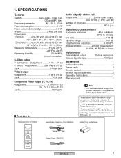
... without notice, due to 85% (no condensation) S-Video output Y (luminance) - TruSurround technology is a registered trademark of measurement (0.001% W. Remote Control : VXX2800 STANDBY/ON OPEN/CLOSE 0 AUDIO SUBTITLE ANGLE 1 2 3 CLEAR 4 5 6 ENTER 7 890 TOP MENU MENU SETUP ENTER RETURN /e 1 E/ 3 ¡ 48 7¢ PLAY MODE SURROUND ZOOM DISPLAY Audio/Video Cable (L=1.5m): XDE3049 White Yellow Red AA/R6P Dry Cell Batteries Power Cable : ADG7022 DV-353-K 5 Output level...........1 Vp-p (75 Ω) C (color) - Accessories • Manufactured under license from...
... without notice, due to 85% (no condensation) S-Video output Y (luminance) - TruSurround technology is a registered trademark of measurement (0.001% W. Remote Control : VXX2800 STANDBY/ON OPEN/CLOSE 0 AUDIO SUBTITLE ANGLE 1 2 3 CLEAR 4 5 6 ENTER 7 890 TOP MENU MENU SETUP ENTER RETURN /e 1 E/ 3 ¡ 48 7¢ PLAY MODE SURROUND ZOOM DISPLAY Audio/Video Cable (L=1.5m): XDE3049 White Yellow Red AA/R6P Dry Cell Batteries Power Cable : ADG7022 DV-353-K 5 Output level...........1 Vp-p (75 Ω) C (color) - Accessories • Manufactured under license from...
Service Manual
Page 9
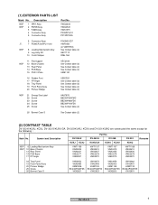
... 18 Tray Panel 19 Front Panel Assy 20 Pioneer Badge 25 Screw 26 Bonnet Case S VNK4952 VXA2486 XAM3006 BCZ40P060FZK VXX2821 VNK4973 VXA2496 VAM1129 BCZ40P060FNI VXX2823 VNK4959 VXA2490 VAM1129 BCZ40P060FZK VXX2830 VNK4962 VXA2491 VAM1130 BCZ40P060FZK VXX2831 DV-353-K 9 VWG2344 VWG2345 VWS1515 PF05PP-Q12 PF13PP-D25 6 Connector Assy > 7 POWER SUPPLY Unit NSP 8 Loading Mechanism Assy 9 Leg Assy SX 10 Cord Clamper...
... 18 Tray Panel 19 Front Panel Assy 20 Pioneer Badge 25 Screw 26 Bonnet Case S VNK4952 VXA2486 XAM3006 BCZ40P060FZK VXX2821 VNK4973 VXA2496 VAM1129 BCZ40P060FNI VXX2823 VNK4959 VXA2490 VAM1129 BCZ40P060FZK VXX2830 VNK4962 VXA2491 VAM1130 BCZ40P060FZK VXX2831 DV-353-K 9 VWG2344 VWG2345 VWS1515 PF05PP-Q12 PF13PP-D25 6 Connector Assy > 7 POWER SUPPLY Unit NSP 8 Loading Mechanism Assy 9 Leg Assy SX 10 Cord Clamper...

Service Manual
Page 16
...; Audio Decode (MP3, Dolby) • Sub-picture Decode SPDIF 57 DOUT 1 - VM5+ 34 35 31 32 15 14 BACK END IC • System Control • MPEG Video Decode PIO381 7 SQUEEZ PIO382 8 LETTER ST1- Focus, Tracking, LOAD_DRV 15 116 HSYNC _PWM0 IC601 Stepper and STI5519AVB-B0C Stepping Motor (Carriage) CN3 (4P) Loading Drive VM1+ VM1- BLOCK DIAGRAM AND SCHEMATIC DIAGRAM 3.1 BLOCK DIAGRAM A 3.1.1 SIGNAL...
...; Audio Decode (MP3, Dolby) • Sub-picture Decode SPDIF 57 DOUT 1 - VM5+ 34 35 31 32 15 14 BACK END IC • System Control • MPEG Video Decode PIO381 7 SQUEEZ PIO382 8 LETTER ST1- Focus, Tracking, LOAD_DRV 15 116 HSYNC _PWM0 IC601 Stepper and STI5519AVB-B0C Stepping Motor (Carriage) CN3 (4P) Loading Drive VM1+ VM1- BLOCK DIAGRAM AND SCHEMATIC DIAGRAM 3.1 BLOCK DIAGRAM A 3.1.1 SIGNAL...

Service Manual
Page 19
... 8 : reference A1 (DVD), T2-chp 1 1 IC301 - pin 27, 28) [S Video output -Y] V: 1V/div. GND 5 Foot of C862 (IC801 - pin 30, 31) [Composite Video output] V: 1V/div. H: 500nsec/div. 8 Foot of R721 (IC711 - H: 1sec/div. V: 2V/div. E F DV-353-K 19 5 6 7 8 pin 3) [AUDIO DAC -LRCK] V: 2V/div. V: 2V/div. 5 6 7 8 3.1.3 WAVEFORMS Note : The encircled numbers denote measuring point in the schematic diagram. H: 0.1µsec...
... 8 : reference A1 (DVD), T2-chp 1 1 IC301 - pin 27, 28) [S Video output -Y] V: 1V/div. GND 5 Foot of C862 (IC801 - pin 30, 31) [Composite Video output] V: 1V/div. H: 500nsec/div. 8 Foot of R721 (IC711 - H: 1sec/div. V: 2V/div. E F DV-353-K 19 5 6 7 8 pin 3) [AUDIO DAC -LRCK] V: 2V/div. V: 2V/div. 5 6 7 8 3.1.3 WAVEFORMS Note : The encircled numbers denote measuring point in the schematic diagram. H: 0.1µsec...

Service Manual
Page 54
... trace, video and audio output are nothing. = Screen display ON/OFF 1. CLV : Press the [TEST] (A8-5E) and [9] (A8-09) keys in order. 2. Repeat focus sweep by pressing the [TEST] (A8-5E) and [CX] (A8-0E) keys in order,then rise up the spindle and it . 3 Tray open / close • Press the [REPEAT A-B] (A8 - 48) key of the remote control unit. •...
... trace, video and audio output are nothing. = Screen display ON/OFF 1. CLV : Press the [TEST] (A8-5E) and [9] (A8-09) keys in order. 2. Repeat focus sweep by pressing the [TEST] (A8-5E) and [CX] (A8-0E) keys in order,then rise up the spindle and it . 3 Tray open / close • Press the [REPEAT A-B] (A8 - 48) key of the remote control unit. •...

Service Manual
Page 56
... FL controller [FL ! Region setting of the player [REG: ∗] Setting value : [1] to [3] 8 Slider position [S CD TOC area : [IN ] CD active area : [CD] 9 Output video system [V NTSC system : [NTSC] PAL system : [PAL] Automatic setting : [AUTO] Skirt terminal output [SK - ∗ ∗] (Display only the WY model which can do the output setting of skirt terminal.) VIDEO : [00] S-VIDEO : [01] RGB : [02] 0 Disc sensing [DSC The type of model. sec.) [0 0 0 0 2 Code indication of remote control...
... FL controller [FL ! Region setting of the player [REG: ∗] Setting value : [1] to [3] 8 Slider position [S CD TOC area : [IN ] CD active area : [CD] 9 Output video system [V NTSC system : [NTSC] PAL system : [PAL] Automatic setting : [AUTO] Skirt terminal output [SK - ∗ ∗] (Display only the WY model which can do the output setting of skirt terminal.) VIDEO : [00] S-VIDEO : [01] RGB : [02] 0 Disc sensing [DSC The type of model. sec.) [0 0 0 0 2 Code indication of remote control...
Service Manual
Page 57
... be DVD with a static image mode as menu screen, confirm it of eight times. DV-353-K 57 After the calculation result, display OK/NG. How to release: Press the "ESC" key. (function with SETUP NAVIGATOR). • Region confirmation mode Input region No. Tray is open the tray. Refer to A8-08 • Service mode indication ID Address Always display error rate. after having pressed the "ESC" key of Model Information Display". • Background color change Change blue...
... be DVD with a static image mode as menu screen, confirm it of eight times. DV-353-K 57 After the calculation result, display OK/NG. How to release: Press the "ESC" key. (function with SETUP NAVIGATOR). • Region confirmation mode Input region No. Tray is open the tray. Refer to A8-08 • Service mode indication ID Address Always display error rate. after having pressed the "ESC" key of Model Information Display". • Background color change Change blue...

Service Manual
Page 58
... Display it according to model information set from the FL controller. 2 Destination indication Display it according to model information set from the FL controller. 3 Region No. 4 Part number 5 ROM version 6 Flash size 7 FL controller version 8 CHIP VERSION Version of ST CHIP CUT ID / JTAG ID (two columns) (eight columns) 9 B.E VERSION Version of BACK END (version of mechanism controller CHIP software) / MainVersion / SubVersion 58 DV-353...
... Display it according to model information set from the FL controller. 2 Destination indication Display it according to model information set from the FL controller. 3 Region No. 4 Part number 5 ROM version 6 Flash size 7 FL controller version 8 CHIP VERSION Version of ST CHIP CUT ID / JTAG ID (two columns) (eight columns) 9 B.E VERSION Version of BACK END (version of mechanism controller CHIP software) / MainVersion / SubVersion 58 DV-353...
Service Manual
Page 60
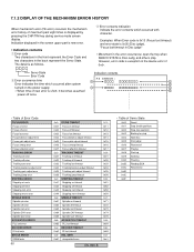
... Error code is 0x13 (Focus lost timeout) and error state is new error. • Indication contents 1 Error code Two characters in the front represent the Error Code and two characters in the device error of 0xd∗. The detail is displayed by pressing the CHP/TIM key during service mode screen display. Indication displayed in the screen upper part is 0x05 (Disc judge), "Focus lost timeout FAIL SAFE unexpected error DV-353...
... Error code is 0x13 (Focus lost timeout) and error state is new error. • Indication contents 1 Error code Two characters in the front represent the Error Code and two characters in the device error of 0xd∗. The detail is displayed by pressing the CHP/TIM key during service mode screen display. Indication displayed in the screen upper part is 0x05 (Disc judge), "Focus lost timeout FAIL SAFE unexpected error DV-353...
Service Manual
Page 61
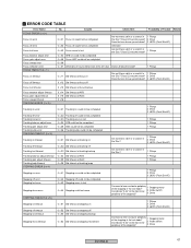
...Driver Does the lens move up and down ? 3. Pickup 1. Driver the Disc? 3. Pickup 1. Driver 1. Driver 3. Does LD become weak? 1. Pickup 1. Do indicate "S-04" at focus off Are not there a dirt or a scratch in 1. Pickup the Disc? Causes Check Item Possibility of Trouble...the test mode? Pickup 1. Pickup 1. Stepping motor Inside switch Driver DV-353-K 61 ERROR CODE TABLE Error Name FOCUS ERROR (0 x 0∗) Focus on error Focus off error Focus lost error Focus balance adjust error Focus gain adjust error Focus sweep error Focus reflection error FOCUS ...
...Driver Does the lens move up and down ? 3. Pickup 1. Driver the Disc? 3. Pickup 1. Driver 1. Driver 3. Does LD become weak? 1. Pickup 1. Do indicate "S-04" at focus off Are not there a dirt or a scratch in 1. Pickup the Disc? Causes Check Item Possibility of Trouble...the test mode? Pickup 1. Pickup 1. Stepping motor Inside switch Driver DV-353-K 61 ERROR CODE TABLE Error Name FOCUS ERROR (0 x 0∗) Focus on error Focus off error Focus lost error Focus balance adjust error Focus gain adjust error Focus sweep error Focus reflection error FOCUS ...

Service Manual
Page 70
... Flow chart from power on to the picture output STANDBY Power on operation by a user (remote controller key or product key) FL controller receives a message FL controller outputs FL lighting / a power on signal (POWER ON: "L"→"H") FL controller resets it for BACK END and removes it (XRESET: "L"→"H") BACK END accesses flash ROM and 64M SDRAM BACK END accesses FRONT END BACK END demands communication from a FL controller (FP_ACK) FL controller outputs the signal which can...
... Flow chart from power on to the picture output STANDBY Power on operation by a user (remote controller key or product key) FL controller receives a message FL controller outputs FL lighting / a power on signal (POWER ON: "L"→"H") FL controller resets it for BACK END and removes it (XRESET: "L"→"H") BACK END accesses flash ROM and 64M SDRAM BACK END accesses FRONT END BACK END demands communication from a FL controller (FP_ACK) FL controller outputs the signal which can...

Service Manual
Page 79
... IN Front Panel interface. (Soft) Serial transfer data output. In case of NOT carusel 5 disc changer, this port is N.C.(output) Carousel 5 Disc Chenger only. Pin Functions Reserved Analog audio output line muteing output 'L'. 3.3 V Power supply Ground Reserved Audio Quality Enhancer IC's chip-select output. S-Video output S1/S2 control signal at letter-box output mode 'H'. Tray rotete puls input. "For EURO(SCART) connecter V/Y, R/C signal select 'L' : VRGB output = VRGB 'H' : VRGB output = YCGB UART(RS-232C) Clear To Send signal input. 2.5 V Power supply...
... IN Front Panel interface. (Soft) Serial transfer data output. In case of NOT carusel 5 disc changer, this port is N.C.(output) Carousel 5 Disc Chenger only. Pin Functions Reserved Analog audio output line muteing output 'L'. 3.3 V Power supply Ground Reserved Audio Quality Enhancer IC's chip-select output. S-Video output S1/S2 control signal at letter-box output mode 'H'. Tray rotete puls input. "For EURO(SCART) connecter V/Y, R/C signal select 'L' : VRGB output = VRGB 'H' : VRGB output = YCGB UART(RS-232C) Clear To Send signal input. 2.5 V Power supply...

Service Manual
Page 80
... Ground Audio DAC clock Audio DAC Front L,R data Audio DAC Center, LFE data Audio DAC Surround L,R data Audio DAC Master clock Audio DAC L/R clock S/PDIF(IEC60958) digital audio output. MIC_ON2 : MIC_ON1 : mode 0 0 : Don't use. 0 1 : Mix to Center Speaker 1 0 : Mix to main L/R channel 1 1 : OFF Reserved In case of NOT Karaoke model, this port is N.C.(output) Carousel 5 Disc Chenger only. 'H' show disc clampe complete postion. OUT SMI SDRAM addresss − 2.5 V Power supply 80 DV-353...
... Ground Audio DAC clock Audio DAC Front L,R data Audio DAC Center, LFE data Audio DAC Surround L,R data Audio DAC Master clock Audio DAC L/R clock S/PDIF(IEC60958) digital audio output. MIC_ON2 : MIC_ON1 : mode 0 0 : Don't use. 0 1 : Mix to Center Speaker 1 0 : Mix to main L/R channel 1 1 : OFF Reserved In case of NOT Karaoke model, this port is N.C.(output) Carousel 5 Disc Chenger only. 'H' show disc clampe complete postion. OUT SMI SDRAM addresss − 2.5 V Power supply 80 DV-353...

Service Manual
Page 85
... (Directly connect to VSS1) Reset Input Serial Clock Input of Serial Interface Serial Data Input of Serial Interface Serial Data Output of Serial Interface Hand-shake (Ready) Output of Serial Interface Power Control Output System Reset Output Reserved (NC on this model) LED Port 8 (NC on this model) Halt Port "NC" : Use Halt Mode Hand-shake (Acknowledge) Input of Serial Interface (Not used on this model) Remote Control Input (Timer input of 8-bit remote control timer) Ground Potential for A/D Converter Destination (of player) Select (Analog Input for A/D Converter) Karaoke model : Echo Volume...
... (Directly connect to VSS1) Reset Input Serial Clock Input of Serial Interface Serial Data Input of Serial Interface Serial Data Output of Serial Interface Hand-shake (Ready) Output of Serial Interface Power Control Output System Reset Output Reserved (NC on this model) LED Port 8 (NC on this model) Halt Port "NC" : Use Halt Mode Hand-shake (Acknowledge) Input of Serial Interface (Not used on this model) Remote Control Input (Timer input of 8-bit remote control timer) Ground Potential for A/D Converter Destination (of player) Select (Analog Input for A/D Converter) Karaoke model : Echo Volume...

Service Manual
Page 96
... playing 2 Lights during multi-angle scenes on a DVD disc 3 GUI (Graphical User Interface) Lights when a menu is displayed on-screen 4 TITLE Indicates that the character display is showing a DVD title number 5 Lights when 2V/TruSurround is active 6 TRK Indicates that the character display is showing a CD or Video CD track number 7 CHP Indicates that the character display is showing a DVD chapter number 8 REMAIN Lights when the character display is showing the time or number...
... playing 2 Lights during multi-angle scenes on a DVD disc 3 GUI (Graphical User Interface) Lights when a menu is displayed on-screen 4 TITLE Indicates that the character display is showing a DVD title number 5 Lights when 2V/TruSurround is active 6 TRK Indicates that the character display is showing a CD or Video CD track number 7 CHP Indicates that the character display is showing a DVD chapter number 8 REMAIN Lights when the character display is showing the time or number...

Service Manual
Page 97
... S-video output that has component video inputs. OPTICAL This is a digital audio output for correct stereo sound. Connect using a commercially available optical digital audio cable. 3 AUDIO OUT L / R This pair of analog audio outputs connects to your TV, AV receiver or stereo system. Even if you are switched off and unplugged. 1 DIGITAL AUDIO OUT - Match the colors of the jacks and cables for connection to a PCM, Dolby Digital, DTS and/or MPEGcompatible AV receiver that has an optical digital input. Rear panel connections 1 23 4 DIGITAL AUDIO OUT...
... S-video output that has component video inputs. OPTICAL This is a digital audio output for correct stereo sound. Connect using a commercially available optical digital audio cable. 3 AUDIO OUT L / R This pair of analog audio outputs connects to your TV, AV receiver or stereo system. Even if you are switched off and unplugged. 1 DIGITAL AUDIO OUT - Match the colors of the jacks and cables for connection to a PCM, Dolby Digital, DTS and/or MPEGcompatible AV receiver that has an optical digital input. Rear panel connections 1 23 4 DIGITAL AUDIO OUT...


