Service Manual
Page 1
... POWER CD PLAYER WITH RDS TUNER DEH-P920R UC MULTI-CD/MD/DAB CONTROL HIGH POWER CD PLAYER WITH RDS TUNER DEH-P9200R UC MULTI-CD CONTROL DSP HIGH POWER CD PLAYER WITH FM/AM TUNER DEH-P9250 ES - Order No. Module:Circuit Description, Mech.Description, Disassembly CONTENTS 1. BLOCK DIAGRAM AND SCHEMATIC DIAGRAM ...14 4. PIONEER EUROPE N.V. Mech. GENERAL INFORMATION 78 7.1 DIAGNOSIS 78 7.1.1 TEST MODE 78 7.1.2 DISASSEMBLY 82 7.2 IC 87 8. ELECTRICAL PARTS...
... POWER CD PLAYER WITH RDS TUNER DEH-P920R UC MULTI-CD/MD/DAB CONTROL HIGH POWER CD PLAYER WITH RDS TUNER DEH-P9200R UC MULTI-CD CONTROL DSP HIGH POWER CD PLAYER WITH FM/AM TUNER DEH-P9250 ES - Order No. Module:Circuit Description, Mech.Description, Disassembly CONTENTS 1. BLOCK DIAGRAM AND SCHEMATIC DIAGRAM ...14 4. PIONEER EUROPE N.V. Mech. GENERAL INFORMATION 78 7.1 DIAGNOSIS 78 7.1.1 TEST MODE 78 7.1.2 DISASSEMBLY 82 7.2 IC 87 8. ELECTRICAL PARTS...
Service Manual
Page 2
..., be sure to turn the power off since an internal IC might be taken to prevent an electrostatic discharge(protection by this product properly and safely; SAFETY INFORMATION CAUTION This service manual is plugged or unplugged. 3. Improperly performed repairs can adversely affect the safety and reliability of California to a qualified service technician. Health & Safety Code Section 25249.6 - DEH-P920R,P9200R,P9250...
..., be sure to turn the power off since an internal IC might be taken to prevent an electrostatic discharge(protection by this product properly and safely; SAFETY INFORMATION CAUTION This service manual is plugged or unplugged. 3. Improperly performed repairs can adversely affect the safety and reliability of California to a qualified service technician. Health & Safety Code Section 25249.6 - DEH-P920R,P9200R,P9250...
Service Manual
Page 4
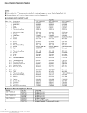
DEH-P920R,P9200R,P9250 NOTE: - PACKING SECTION PARTS LIST Mark No. 1 2 * 3 * 4 5 Description Cord Assy Base Assy Base Sheet Polyethylene Bag DEH-P920R/UC CDE6336 CEA2426 CNS5031 CZA3371 CZE3188 Part No. Owner's Manual, Installation Manual Model Part No. Parts marked by "*" are generally unavailable because they are used * CEG1088(Cover) CEG1192 CEX1006 24 Carton 25 Contain Box 26 Protector 27 Protector 28 Remote Control Assy CHG4039 CHL4039 CHP2032 CHP2033...
DEH-P920R,P9200R,P9250 NOTE: - PACKING SECTION PARTS LIST Mark No. 1 2 * 3 * 4 5 Description Cord Assy Base Assy Base Sheet Polyethylene Bag DEH-P920R/UC CDE6336 CEA2426 CNS5031 CZA3371 CZE3188 Part No. Owner's Manual, Installation Manual Model Part No. Parts marked by "*" are generally unavailable because they are used * CEG1088(Cover) CEG1192 CEX1006 24 Carton 25 Contain Box 26 Protector 27 Protector 28 Remote Control Assy CHG4039 CHL4039 CHP2032 CHP2033...

Service Manual
Page 14
... SYS+B TUN5V POWER ON MUTE IC 401 S-81250SGUP B.U CN101 IP-BUS CONNECTOR DEH-P920R/UC Q501 RDS DECODER 24 VDD fm/AM 20 IC 501 PM4009A 11 12 X501 Q101 B.U ASENBO 8 5 BUS2 1 BUS1 Q102 IP-BUS DRIVER 5 IC 101 1 TX 6 CA008AM 2 RX 8 IPPW 7 BUS+L 11 BUS-L PICKUP UNIT(SERVICE) LD MD LD+ MD HOLOGRAM UNIT FOCUS ACT FO+ TRACKING ACT TO+ H CONTROL UNIT CN101 14...
... SYS+B TUN5V POWER ON MUTE IC 401 S-81250SGUP B.U CN101 IP-BUS CONNECTOR DEH-P920R/UC Q501 RDS DECODER 24 VDD fm/AM 20 IC 501 PM4009A 11 12 X501 Q101 B.U ASENBO 8 5 BUS2 1 BUS1 Q102 IP-BUS DRIVER 5 IC 101 1 TX 6 CA008AM 2 RX 8 IPPW 7 BUS+L 11 BUS-L PICKUP UNIT(SERVICE) LD MD LD+ MD HOLOGRAM UNIT FOCUS ACT FO+ TRACKING ACT TO+ H CONTROL UNIT CN101 14...

Service Manual
Page 16
1 2 3 4 DEH-P920R,P9200R,P9250 A 3.2 BLOCK DIAGRAM(DEH-P9200R/UC) A TUNER AMP UNIT ANT GND2 B CN451 1 2 B FM/AM TUNER UNIT FM FRONT END Q3 FM/AM 1ST IF 10.7MHz T51 Q51 CF51 CF52 CF53 FM MPX 25 24 27 32 IC 2 ... 37 IN1_R ELECTRICAL VO SOURCE SELE IC 203 PML004AF 24 PEE 9 LEVEL L 7 ASENS 7 BSENS 2 ISENS 1 TELIN 8 DRSYS 8 DRSENS 7 DRELAY 2 SYSPW SYSTEM CONTROLLER IC 601(2/2) PD5487C 2 MUTE 26 FLPPW 34 FLPOPN 37 FLPCLS 40 FCLSSW 38 FOPNSW 4 DSENS 3 KYDT 3 DPDT 1 RESET D 4 FLPILM 4 OEL PW 4 ILMPW 4 SWVDD 16 Downloaded from ww1w.Manualslib.com manuals search engin2e 3 4
1 2 3 4 DEH-P920R,P9200R,P9250 A 3.2 BLOCK DIAGRAM(DEH-P9200R/UC) A TUNER AMP UNIT ANT GND2 B CN451 1 2 B FM/AM TUNER UNIT FM FRONT END Q3 FM/AM 1ST IF 10.7MHz T51 Q51 CF51 CF52 CF53 FM MPX 25 24 27 32 IC 2 ... 37 IN1_R ELECTRICAL VO SOURCE SELE IC 203 PML004AF 24 PEE 9 LEVEL L 7 ASENS 7 BSENS 2 ISENS 1 TELIN 8 DRSYS 8 DRSENS 7 DRELAY 2 SYSPW SYSTEM CONTROLLER IC 601(2/2) PD5487C 2 MUTE 26 FLPPW 34 FLPOPN 37 FLPCLS 40 FCLSSW 38 FOPNSW 4 DSENS 3 KYDT 3 DPDT 1 RESET D 4 FLPILM 4 OEL PW 4 ILMPW 4 SWVDD 16 Downloaded from ww1w.Manualslib.com manuals search engin2e 3 4
Service Manual
Page 74
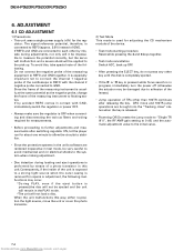
... unit or cover the photo transistor. 2) Test Mode This mode is used for adjusting the CD mechanism module of the oscilloscope to REFO with GND, immediately switch the regulator or power OFF. • Always make sure the regulator is connected to REFO(approx. 2.5V) instead of the measuring instrument to connect the channel 1 negative probe of the device. • Test mode starting procedure Reset...
... unit or cover the photo transistor. 2) Test Mode This mode is used for adjusting the CD mechanism module of the oscilloscope to REFO with GND, immediately switch the regulator or power OFF. • Always make sure the regulator is connected to REFO(approx. 2.5V) instead of the measuring instrument to connect the channel 1 negative probe of the device. • Test mode starting procedure Reset...

Service Manual
Page 78
... disc. Sub-code is indicated with a corresponding number. Focus can 't be determined. → CD signal error. 17 Electricity Setup NG APC protection doesn't work in servicing. (1) Basic Indication Method 1) When SERRORM is selected for the CSMOD (CD mode area for the system), error codes are not displayed (because a CD is turned off in these errors). Unreadable TOC does not constitute an error. Error Messages If a CD is not operative...
... disc. Sub-code is indicated with a corresponding number. Focus can 't be determined. → CD signal error. 17 Electricity Setup NG APC protection doesn't work in servicing. (1) Basic Indication Method 1) When SERRORM is selected for the CSMOD (CD mode area for the system), error codes are not displayed (because a CD is turned off in these errors). Unreadable TOC does not constitute an error. Error Messages If a CD is not operative...

Service Manual
Page 79
... servo. FOK = Low continued for the normal mode. (3) Cause of the [SOURCE] key, and inserting the disc. FWD-Kick FF/TR+ - [- Sub-code was activated. → Damages/stains on disc, vibrations or failure on servo. 43 Electricity Sound skipping detected. T.Close (AGC performed) Scan - /parameter display switching 2 RF AMP gain switching Parameter display switching Mode - /T.BAL adjustment/T.Open 3 To power on servo. 42 Electricity Sub-code unreadable. DEH-P920R,P9200R,P9250 -
... servo. FOK = Low continued for the normal mode. (3) Cause of the [SOURCE] key, and inserting the disc. FWD-Kick FF/TR+ - [- Sub-code was activated. → Damages/stains on disc, vibrations or failure on servo. 43 Electricity Sound skipping detected. T.Close (AGC performed) Scan - /parameter display switching 2 RF AMP gain switching Parameter display switching Mode - /T.BAL adjustment/T.Open 3 To power on servo. 42 Electricity Sub-code unreadable. DEH-P920R,P9200R,P9250 -

Service Manual
Page 83
Remove the screw B. 3. Disconnect the connector, and then remove the DSP Unit. C Tuner Amp Unit Case DSP Unit 83 Downloaded from www.Manualslib.com manuals search engine Remove the Tuner Amp Unit (2/2) 1. Stretch the four tabs, and then remove the Tuner Amp Unit. Remove the screw A, four screws C, and then remove the Antenna Cable and Holder. 2. DEH-P920R,P9200R,P9250 Antenna Cable A Holder B CC C - Remove the DSP Unit(DEH-P920R/UC, DEH-P9250/ES) 1. - Remove the three solder of tabs indicated by arrows, and then remove the Case. 2.
Remove the screw B. 3. Disconnect the connector, and then remove the DSP Unit. C Tuner Amp Unit Case DSP Unit 83 Downloaded from www.Manualslib.com manuals search engine Remove the Tuner Amp Unit (2/2) 1. Stretch the four tabs, and then remove the Tuner Amp Unit. Remove the screw A, four screws C, and then remove the Antenna Cable and Holder. 2. DEH-P920R,P9200R,P9250 Antenna Cable A Holder B CC C - Remove the DSP Unit(DEH-P920R/UC, DEH-P9250/ES) 1. - Remove the three solder of tabs indicated by arrows, and then remove the Case. 2.

Service Manual
Page 90
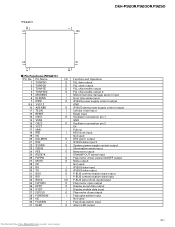
... LEVELR LEVELL NC SD_BW NC VSS5 SL VREF VCC4 TUNPDI I/O Function and Operation Not used O Inside of flap illumination output O Illumination power supply control output O Display chip select output O OEL module power supply control output I Grille detach sense input I FM stereo input I SD input Not used 5V Not used GND O E-VOL clock output / ROM correction clock output O/I E-VOL data output / ROM correction data input O/I E-VOL strobe pulse output / P-BUS communication input/output Not used I/O P-BUS communication input/output O P-BUS reset output I/O P-BUS communication...
... LEVELR LEVELL NC SD_BW NC VSS5 SL VREF VCC4 TUNPDI I/O Function and Operation Not used O Inside of flap illumination output O Illumination power supply control output O Display chip select output O OEL module power supply control output I Grille detach sense input I FM stereo input I SD input Not used 5V Not used GND O E-VOL clock output / ROM correction clock output O/I E-VOL data output / ROM correction data input O/I E-VOL strobe pulse output / P-BUS communication input/output Not used I/O P-BUS communication input/output O P-BUS reset output I/O P-BUS communication...
Service Manual
Page 91
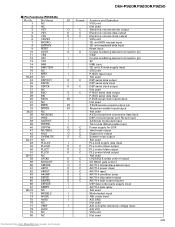
...I/O Function and Operation O PLL data output O PLL clock output O PLL chip enable output O PLL chip enable output 2 I Motion/window damage sensor input I Door lock sense input O IP-BUS power supply control output GND O IP-BUS slave power supply control output I Cellular mute input I Reset input O Oscillator connection pin 1 GND O Oscillator connection pin 2 5V Pull up I RDS clock input Not used O DFS alarm output I IP-BUS data input 2 O System power supply control output I Illumination sense input O Beep tone output I 57kHzBP-OUT sense input O Flap motor driver...
...I/O Function and Operation O PLL data output O PLL clock output O PLL chip enable output O PLL chip enable output 2 I Motion/window damage sensor input I Door lock sense input O IP-BUS power supply control output GND O IP-BUS slave power supply control output I Cellular mute input I Reset input O Oscillator connection pin 1 GND O Oscillator connection pin 2 5V Pull up I RDS clock input Not used O DFS alarm output I IP-BUS data input 2 O System power supply control output I Illumination sense input O Beep tone output I 57kHzBP-OUT sense input O Flap motor driver...

Service Manual
Page 92
... LEVELR LEVELL NC SD_BW NC VSS5 SL VREF VCC4 TUNPDI I/O Function and Operation Not used O Inside of flap illumination output O Illumination power supply control output O Display chip select output O OEL module power supply control output I Grille detach sense input I FM stereo input I SD input Not used 5V Not used GND O E-VOL clock output / ROM correction clock output O/I E-VOL data output / ROM correction data input O/I E-VOL strobe pulse output / P-BUS communication input/output Not used I/O P-BUS communication input/output O P-BUS reset output I/O P-BUS communication...
... LEVELR LEVELL NC SD_BW NC VSS5 SL VREF VCC4 TUNPDI I/O Function and Operation Not used O Inside of flap illumination output O Illumination power supply control output O Display chip select output O OEL module power supply control output I Grille detach sense input I FM stereo input I SD input Not used 5V Not used GND O E-VOL clock output / ROM correction clock output O/I E-VOL data output / ROM correction data input O/I E-VOL strobe pulse output / P-BUS communication input/output Not used I/O P-BUS communication input/output O P-BUS reset output I/O P-BUS communication...
Service Manual
Page 95
... control data output O C PLL control clock output Not used O C LRCK/BCLK select control output O C CD MCLK gate control O C AK7714 master/slave select input O C AK7714 power down O C AK7714 reset O C AK7714 condition jump O C AK7714 chip select output O C AK7714 data output request I DSP data write ready supply input I AK7714 data ready Not used I Model select input I ASL noise input I A/D GND Not used I A/D converter reference voltage input A/D VCC VSS joint Not used 95 Downloaded from www.Manualslib.com manuals search engine DEH-P920R,P9200R...
... control data output O C PLL control clock output Not used O C LRCK/BCLK select control output O C CD MCLK gate control O C AK7714 master/slave select input O C AK7714 power down O C AK7714 reset O C AK7714 condition jump O C AK7714 chip select output O C AK7714 data output request I DSP data write ready supply input I AK7714 data ready Not used I Model select input I ASL noise input I A/D GND Not used I A/D converter reference voltage input A/D VCC VSS joint Not used 95 Downloaded from www.Manualslib.com manuals search engine DEH-P920R,P9200R...

Service Manual
Page 99
... clock fs select Bit expand select Not used LRCKO polarity select LRCKO output Not used Bit clock output Data output GND Power supply terminal LRCKO input Not used Data input Bit clock input Not used Open O C CD LSI data discrimination control signal output O C CD LSI strobe output O C CD LSI reset output I CD LSI serial data input P-Bus reset input CD-TEXT pack sync signal input Not used Bit expand/input data output select Reset input - Pin Functions(PE5011C) Pin No. PD0236AM 9 1 DEH-P920R,P9200R,P9250 10 18 - Pin Functions (PD0236AM) Pin...
... clock fs select Bit expand select Not used LRCKO polarity select LRCKO output Not used Bit clock output Data output GND Power supply terminal LRCKO input Not used Data input Bit clock input Not used Open O C CD LSI data discrimination control signal output O C CD LSI strobe output O C CD LSI reset output I CD LSI serial data input P-Bus reset input CD-TEXT pack sync signal input Not used Bit expand/input data output select Reset input - Pin Functions(PE5011C) Pin No. PD0236AM 9 1 DEH-P920R,P9200R,P9250 10 18 - Pin Functions (PD0236AM) Pin...

Service Manual
Page 100
... Input/output by which P-Bus can be received O C P-Bus polling request output Not used Open O C Servo driver power supply control output O C CD mute control output O C Load/Eject motor Eject control output O C Load/Eject motor Load control output O C Bus mute output I Disc clamp input Not used Open Not used VDD or VSS I Tx output set selection input O C Flash writing clock input(Open) O C Flash writing data output(Open) O C Flash writing data input(Open) I/O /C P-Bus serial clock input/output I/O /C P-Bus serial data input/output I Test program start...
... Input/output by which P-Bus can be received O C P-Bus polling request output Not used Open O C Servo driver power supply control output O C CD mute control output O C Load/Eject motor Eject control output O C Load/Eject motor Load control output O C Bus mute output I Disc clamp input Not used Open Not used VDD or VSS I Tx output set selection input O C Flash writing clock input(Open) O C Flash writing data output(Open) O C Flash writing data input(Open) I/O /C P-Bus serial clock input/output I/O /C P-Bus serial data input/output I Test program start...

Service Manual
Page 102
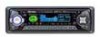
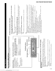
... volume level. +/- button PGM button CLOCK button SOURCE/OFF button LOUD button AUDIO button Remote Controller A remote controller that enables remote operation of the head unit is the same as when using buttons on the head unit. button Raise or lower the volume. 5/∞ buttons BAND button PGM button FUNCTION button SOURCE/OFF button AUDIO button 2/3 buttons 102 Downloaded from www.Manualslib.com manuals search engine Operation is supplied. DEH-P920R,P9200R,P9250 Head Unit(DEH-P9250/ES) EQ selector DISPLAY button RESET button FUNCTION button ENTERTAINMENT button...
... volume level. +/- button PGM button CLOCK button SOURCE/OFF button LOUD button AUDIO button Remote Controller A remote controller that enables remote operation of the head unit is the same as when using buttons on the head unit. button Raise or lower the volume. 5/∞ buttons BAND button PGM button FUNCTION button SOURCE/OFF button AUDIO button 2/3 buttons 102 Downloaded from www.Manualslib.com manuals search engine Operation is supplied. DEH-P920R,P9200R,P9250 Head Unit(DEH-P9250/ES) EQ selector DISPLAY button RESET button FUNCTION button ENTERTAINMENT button...
Service Manual
Page 103
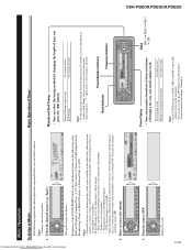
... antenna, switch the source OFF. 2. Basic Operation of time you press the 2/3 button. patible as one -touch station recall. Hold for easy, one available in the future) that, although incom- Tuner). Seek Tuning starts as soon as you release the button. • Stereo indicator " " lights when a stereo station is connected to the car's Auto-antenna relay control terminal, the car's Auto-antenna extends when this product. 1. Band Indicator Preset Number Indicator Frequency Indicator DEH-P920R,P9200R,P9250 3. Downloaded...
... antenna, switch the source OFF. 2. Basic Operation of time you press the 2/3 button. patible as one -touch station recall. Hold for easy, one available in the future) that, although incom- Tuner). Seek Tuning starts as soon as you release the button. • Stereo indicator " " lights when a stereo station is connected to the car's Auto-antenna relay control terminal, the car's Auto-antenna extends when this product. 1. Band Indicator Preset Number Indicator Frequency Indicator DEH-P920R,P9200R,P9250 3. Downloaded...
Service Manual
Page 105
... DISPLAY button changes the display in the Detailed Setting Menu. "No Title") is read. Downloaded from the extra tray to the magazine. (Refer to the 50-Disc Type Multi-CD Player Owner's Manual.) • You cannot use the "Ejecting a Single Disc", "Frequency Play", "Music Group Play" or "ABC Disc Title Search" functions with the 1 to 6 buttons. Track Search Fast Forward/Reverse 0.5 seconds or less Continue pressing Track Number Indicator Disc Number Indicator Play Time Indicator Disc Search Switching...
... DISPLAY button changes the display in the Detailed Setting Menu. "No Title") is read. Downloaded from the extra tray to the magazine. (Refer to the 50-Disc Type Multi-CD Player Owner's Manual.) • You cannot use the "Ejecting a Single Disc", "Frequency Play", "Music Group Play" or "ABC Disc Title Search" functions with the 1 to 6 buttons. Track Search Fast Forward/Reverse 0.5 seconds or less Continue pressing Track Number Indicator Disc Number Indicator Play Time Indicator Disc Search Switching...

Service Manual
Page 106
...: Super Bass, Powerful, Natural and Vocal. Adjust front/rear speaker balance with the 2/3 buttons. Note: • When the Rear Speaker Output setting is the proper setting when 2 speakers are two types of the equalizer curves by the Autoequalizing function, this menu, you to rear. 3. Press the AUDIO button and select the Fader/Balance mode (FAD/BAL) in the Audio Menu 1. 1. "Balance Left:9" - Cancel the Audio Menu 1. DEH-P920R,P9200R,P9250 106 Downloaded from www.Manualslib.com manuals search engine Audio Adjustment Selecting the Equalizer Curve...
...: Super Bass, Powerful, Natural and Vocal. Adjust front/rear speaker balance with the 2/3 buttons. Note: • When the Rear Speaker Output setting is the proper setting when 2 speakers are two types of the equalizer curves by the Autoequalizing function, this menu, you to rear. 3. Press the AUDIO button and select the Fader/Balance mode (FAD/BAL) in the Audio Menu 1. 1. "Balance Left:9" - Cancel the Audio Menu 1. DEH-P920R,P9200R,P9250 106 Downloaded from www.Manualslib.com manuals search engine Audio Adjustment Selecting the Equalizer Curve...
Service Manual
Page 107
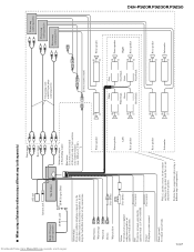
...; + + Subwoofer ≠ ≠ DEH-P920R,P9200R,P9250 Orange To lighting switch terminal. Perform these connections when using a different amp (sold separately) ASL unit Antenna jack Multi-CD player (sold separately). Downloaded from www.Manualslib.com manuals search engine 107 7 When using a Subwoofer without using a different amp (sold separately) This Product IP-BUS cable IP-BUS input (Blue) Yellow/black If you use a cellular telephone, connect it via the Audio Mute lead on the cellular telephone. Front output Rear output Subwoofer output...
...; + + Subwoofer ≠ ≠ DEH-P920R,P9200R,P9250 Orange To lighting switch terminal. Perform these connections when using a different amp (sold separately) ASL unit Antenna jack Multi-CD player (sold separately). Downloaded from www.Manualslib.com manuals search engine 107 7 When using a Subwoofer without using a different amp (sold separately) This Product IP-BUS cable IP-BUS input (Blue) Yellow/black If you use a cellular telephone, connect it via the Audio Mute lead on the cellular telephone. Front output Rear output Subwoofer output...


