Service Manual
Page 1
... MULTI-CD CONTROL HIGH POWER CD PLAYER WITH FM/AM TUNER DEH-P300 DEH-P3000 X1N/UC DEH-P200 X1N/UC ORDER NO. SAFETY INFORMATION 2 2. ELECTRICAL PARTS LIST 44 6. P.O.Box 1760, Long Beach, CA 90801-1760 U.S.A. PIONEER ELECTRONIC [EUROPE] N.V. Haven 1087 Keetberglaan 1, 9120 Melsele, Belgium PIONEER ELECTRONICS ASIACENTRE PTE.LTD. 253 Alexandra Road, #04-01, Singapore 159936...
... MULTI-CD CONTROL HIGH POWER CD PLAYER WITH FM/AM TUNER DEH-P300 DEH-P3000 X1N/UC DEH-P200 X1N/UC ORDER NO. SAFETY INFORMATION 2 2. ELECTRICAL PARTS LIST 44 6. P.O.Box 1760, Long Beach, CA 90801-1760 U.S.A. PIONEER ELECTRONIC [EUROPE] N.V. Haven 1087 Keetberglaan 1, 9120 Melsele, Belgium PIONEER ELECTRONICS ASIACENTRE PTE.LTD. 253 Alexandra Road, #04-01, Singapore 159936...
Service Manual
Page 2
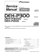
...). 1. Proposition 65 2. If you should not risk trying to do -it-yourselfer. Please checking the grating after changing the service pickup unit(see page 54). DEH-P300,P3000,P200 - EXPLODED VIEWS AND PARTS LIST 2.1 PACKING 2 6 7 4 8 5 10 3 11 9 16 15 19 1 12 20 17 14 2 During replacement, handling precautions shall be destroyed when a connector...
...). 1. Proposition 65 2. If you should not risk trying to do -it-yourselfer. Please checking the grating after changing the service pickup unit(see page 54). DEH-P300,P3000,P200 - EXPLODED VIEWS AND PARTS LIST 2.1 PACKING 2 6 7 4 8 5 10 3 11 9 16 15 19 1 12 20 17 14 2 During replacement, handling precautions shall be destroyed when a connector...
Service Manual
Page 3
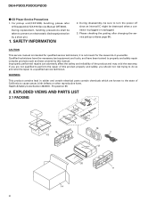
... 12 Polyethylene Bag 13 14 Carton 15 Contain Box CNV3930 CEG1173 See Contrast table(2) See Contrast table(2) (2) CONTRAST TABLE DEH-P300/X1N/UC, DEH-P3000/X1N/UC and DEH-P200/X1N/UC are not in our Master Spare Parts List. - CDE5769 CEA2395 CBH1650 CEA2396 CBA1002 Mark No. CRD2823 ... CRY1070 * 20-5 Card Not used for the following: Mark No. Owner's Manual Model DEH-P300/X1N/UC, DEH-P200/X1N/UC DEH-P3000/X1N/UC - DEH-P3000/X1N/UC CHG3644 CHL3644 CRD2820 CRD2821 Not used DEH-P200/X1N/UC CHG3658 CHL3658 CRD2822 CRD2850 CRY1070 ARY1048 Not used - Description 16 Protector 17 ...
... 12 Polyethylene Bag 13 14 Carton 15 Contain Box CNV3930 CEG1173 See Contrast table(2) See Contrast table(2) (2) CONTRAST TABLE DEH-P300/X1N/UC, DEH-P3000/X1N/UC and DEH-P200/X1N/UC are not in our Master Spare Parts List. - CDE5769 CEA2395 CBH1650 CEA2396 CBA1002 Mark No. CRD2823 ... CRY1070 * 20-5 Card Not used for the following: Mark No. Owner's Manual Model DEH-P300/X1N/UC, DEH-P200/X1N/UC DEH-P3000/X1N/UC - DEH-P3000/X1N/UC CHG3644 CHL3644 CRD2820 CRD2821 Not used DEH-P200/X1N/UC CHG3658 CHL3658 CRD2822 CRD2850 CRY1070 ARY1048 Not used - Description 16 Protector 17 ...

Service Manual
Page 5
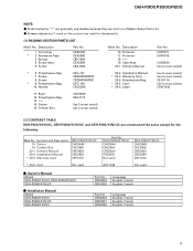
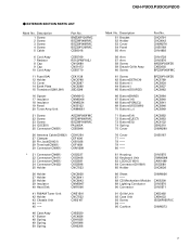
... Case Unit 93 Screw 94 95 Cushion CXB3493 CXB4033 ISS26P055FUC CNM6373 5 Description 1 Screw 2 Screw 3 Screw 4 Screw 5 Cable Part No. EXTERIOR SECTION PARTS LIST Mark No. DEH-P300,P3000,P200 -
... Case Unit 93 Screw 94 95 Cushion CXB3493 CXB4033 ISS26P055FUC CNM6373 5 Description 1 Screw 2 Screw 3 Screw 4 Screw 5 Cable Part No. EXTERIOR SECTION PARTS LIST Mark No. DEH-P300,P3000,P200 -
Service Manual
Page 7
DEH-P300,P3000,P200 - Description 1 Screw 2 Screw 3 Screw 4 Screw 5 Cable Part No. Description 51 Bracket 52 Holder 53 Cover 54 Panel 55 Arm Part No. EXTERIOR SECTION PARTS ...
DEH-P300,P3000,P200 - Description 1 Screw 2 Screw 3 Screw 4 Screw 5 Cable Part No. Description 51 Bracket 52 Holder 53 Cover 54 Panel 55 Arm Part No. EXTERIOR SECTION PARTS ...

Service Manual
Page 9
... Module 89 Lighting Conductor 90 Connector CNM6026 CXK5200 CNV5570 CNV5571 91 Grille Unit 92 Case Unit 93 Screw 94 95 Cushion CXB3497 CXB4033 ISS26P055FUC CNM6373 9 DEH-P300,P3000,P200 - BMZ26P120FMC BSZ26P060FMC BSZ30P060FMC BSZ30P120FMC CDE6018 6 Cord Assy 7 Resistor 8 Cap 9 Cap 10 Cord Assy CDE5769 RS1/2PMF102J CNV2680 CNS1472 CDE5770 11 Fuse(10A) 12 Holder...
... Module 89 Lighting Conductor 90 Connector CNM6026 CXK5200 CNV5570 CNV5571 91 Grille Unit 92 Case Unit 93 Screw 94 95 Cushion CXB3497 CXB4033 ISS26P055FUC CNM6373 9 DEH-P300,P3000,P200 - BMZ26P120FMC BSZ26P060FMC BSZ30P060FMC BSZ30P120FMC CDE6018 6 Cord Assy 7 Resistor 8 Cap 9 Cap 10 Cord Assy CDE5769 RS1/2PMF102J CNV2680 CNS1472 CDE5770 11 Fuse(10A) 12 Holder...
Service Manual
Page 11
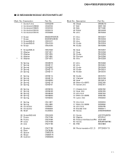
DEH-P300,P3000,P200 - CD MECHANISM MODULE SECTION PARTS LIST Mark No. CWX2344 CKS2192 CKS2193 CKS2773 CKS3486 BMZ20P030FZK BSZ20P040FZK CBA1077 CBA1230 CBA1243 CBA1362 CBF1037 CBF1038 CBF1060 CBF1075 CBH2079 ...
DEH-P300,P3000,P200 - CD MECHANISM MODULE SECTION PARTS LIST Mark No. CWX2344 CKS2192 CKS2193 CKS2773 CKS3486 BMZ20P030FZK BSZ20P040FZK CBA1077 CBA1230 CBA1243 CBA1362 CBF1037 CBF1038 CBF1060 CBF1075 CBH2079 ...
Service Manual
Page 12
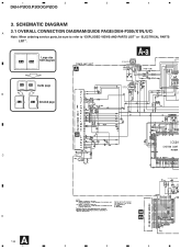
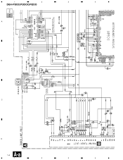
SCHEMATIC DIAGRAM 3.1 OVERALL CONNECTION DIAGRAM(GUIDE PAGE)(DEH-P300/X1N/UC) A Note: When ordering service parts, be sure to refer to "EXPLODED VIEWS AND PARTS LIST" or "ELECTRICAL PARTS LIST". 1 2 3 4 DEH-P300,P3000,P200 3. Large size A-a A-b SCH diagram A A-a IP BUS IN 4.3V 4.3V 4.3V 4.3V 4.3V A-a A-b Guide page B A-a A-b Detailed page IP BUS DRIVER 4.3V 4.3V 4.3V SO EL 4.3V 4.3V B DE C ANTENNA CABLE D A 12 1 2 3 VD REGULATOR 4
SCHEMATIC DIAGRAM 3.1 OVERALL CONNECTION DIAGRAM(GUIDE PAGE)(DEH-P300/X1N/UC) A Note: When ordering service parts, be sure to refer to "EXPLODED VIEWS AND PARTS LIST" or "ELECTRICAL PARTS LIST". 1 2 3 4 DEH-P300,P3000,P200 3. Large size A-a A-b SCH diagram A A-a IP BUS IN 4.3V 4.3V 4.3V 4.3V 4.3V A-a A-b Guide page B A-a A-b Detailed page IP BUS DRIVER 4.3V 4.3V 4.3V SO EL 4.3V 4.3V B DE C ANTENNA CABLE D A 12 1 2 3 VD REGULATOR 4
Service Manual
Page 13
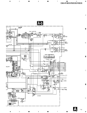
5 6 4.3V 4.3V 4.3V 4.3V URCE SELECTOR, ECTRONIC VOLUME 4.3V 4.2V 1.8V 4.2V A-b 4.2V RESET 7 8 DEH-P300,P3000,P200 A B CEK1136 CEK1014 C D C A 13 5 6 7 8
5 6 4.3V 4.3V 4.3V 4.3V URCE SELECTOR, ECTRONIC VOLUME 4.3V 4.2V 1.8V 4.2V A-b 4.2V RESET 7 8 DEH-P300,P3000,P200 A B CEK1136 CEK1014 C D C A 13 5 6 7 8
Service Manual
Page 14
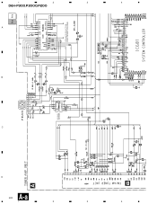
4 3 2 1 14 A-a A B D C B IP BUS IN IP BUS DRIVER A-a A-b 4.3V 4.3V 4.3V 4.3V 4.3V 4.3V 4.3V 4.3V 4.3V 4.3V 4.3V 4.3V SOURCE SELECTOR, ELECTRONIC VOLUME 4.3V 4.3V A DEH-P300,P3000,P200 4 3 2 1
4 3 2 1 14 A-a A B D C B IP BUS IN IP BUS DRIVER A-a A-b 4.3V 4.3V 4.3V 4.3V 4.3V 4.3V 4.3V 4.3V 4.3V 4.3V 4.3V 4.3V SOURCE SELECTOR, ELECTRONIC VOLUME 4.3V 4.3V A DEH-P300,P3000,P200 4 3 2 1
Service Manual
Page 20
4 3 2 1 20 A-a A B D C B IP BUS IN IP BUS DRIVER A-a A-b 4.3V 4.3V 4.3V 4.3V 4.3V 4.3V 4.3V 4.3V 4.3V 4.3V 4.3V 4.3V SOURCE SELECTOR, ELECTRONIC VOLUME 4.3V 4.3V A DEH-P300,P3000,P200 4 3 2 1
4 3 2 1 20 A-a A B D C B IP BUS IN IP BUS DRIVER A-a A-b 4.3V 4.3V 4.3V 4.3V 4.3V 4.3V 4.3V 4.3V 4.3V 4.3V 4.3V 4.3V SOURCE SELECTOR, ELECTRONIC VOLUME 4.3V 4.3V A DEH-P300,P3000,P200 4 3 2 1
Service Manual
Page 24
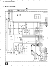
1 2 DEH-P300,P3000,P200 3.3 FM/AM TUNER UNIT A B B 3 4 A Voltage of IC Terminals Mark Band Input Level None - - F0 FM 0dBf F65 FM 65dBf F125 FM A0 AM A74 AM A125 AM 125dBf 0dBµ 74dBµ 125dBµ KV1410(23) C D B 24 1 2 3 4
1 2 DEH-P300,P3000,P200 3.3 FM/AM TUNER UNIT A B B 3 4 A Voltage of IC Terminals Mark Band Input Level None - - F0 FM 0dBf F65 FM 65dBf F125 FM A0 AM A74 AM A125 AM 125dBf 0dBµ 74dBµ 125dBµ KV1410(23) C D B 24 1 2 3 4

Service Manual
Page 29
5 6 7 8 DEH-P300,P3000,P200 A SWITCHES: CONTROL UNIT S801 : HOME SWITCH.....ON-OFF S802 : CLAMP SWITCH....ON-OFF The underlined indicates the switch position. B C A CN681 D D 29 5 6 7 8
5 6 7 8 DEH-P300,P3000,P200 A SWITCHES: CONTROL UNIT S801 : HOME SWITCH.....ON-OFF S802 : CLAMP SWITCH....ON-OFF The underlined indicates the switch position. B C A CN681 D D 29 5 6 7 8
Service Manual
Page 30
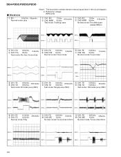
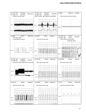
... close 6 CH1: FE 7 CH2: XSI 0.5V/div. 1ms/div. 2V/div. Normal mode: Focus close 3 CH1: FD 0.5V/div. 0.2s/div. 5 CH2: FOK 2V/div. DEH-P300,P3000,P200 - Test mode: Tracking open 1 CH1: RFI 1V/div. 2 CH2: MIRR 5V/div. 0.5ms/div.
... close 6 CH1: FE 7 CH2: XSI 0.5V/div. 1ms/div. 2V/div. Normal mode: Focus close 3 CH1: FD 0.5V/div. 0.2s/div. 5 CH2: FOK 2V/div. DEH-P300,P3000,P200 - Test mode: Tracking open 1 CH1: RFI 1V/div. 2 CH2: MIRR 5V/div. 0.5ms/div.
Service Manual
Page 31
.... 2ms/div. # CH2: TEC 1V/div. Normal mode: play 10µs/div. & LRCK 2V/div. 20µs/div. Normal mode: play 20ms/div. 8 CH1: TE ! DEH-P300,P3000,P200 8 CH1: TE 0.2V/div. 9 CH2: TD 0.2V/div. TEST mode: 100 Tracks jump(FWD) Normal mode: Play (12cm) REFO → REFO → REFO →...
.... 2ms/div. # CH2: TEC 1V/div. Normal mode: play 10µs/div. & LRCK 2V/div. 20µs/div. Normal mode: play 20ms/div. 8 CH1: TE ! DEH-P300,P3000,P200 8 CH1: TE 0.2V/div. 9 CH2: TD 0.2V/div. TEST mode: 100 Tracks jump(FWD) Normal mode: Play (12cm) REFO → REFO → REFO →...

Service Manual
Page 32
...: During AGC REFO → REFO → REFO → REFO → REFO → REFO → 1 CH1: RFI ⁄ CH2: HOLD 1V/div. 5V/div. 0.5ms/div. DEH-P300,P3000,P200 ( CH1: R OUT 1V/div. ) CH2: L OUT 1V/div. 0.2ms/div. 6 CH1: FE 3 CH2: FD 0.2V/div. 0.5V/div. 1ms/div. 8 CH1: TE 9 CH2: TD...
...: During AGC REFO → REFO → REFO → REFO → REFO → REFO → 1 CH1: RFI ⁄ CH2: HOLD 1V/div. 5V/div. 0.5ms/div. DEH-P300,P3000,P200 ( CH1: R OUT 1V/div. ) CH2: L OUT 1V/div. 0.2ms/div. 6 CH1: FE 3 CH2: FD 0.2V/div. 0.5V/div. 1ms/div. 8 CH1: TE 9 CH2: TD...
Service Manual
Page 34
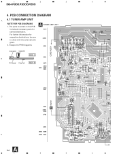
gram. 2. Viewpoint of PCB diagrams CORD ASSY Connector Capacitor SIDE A B P.C.Board Chip Part SIDE B C D CN701 D A 34 1 2 3 4 1 2 3 4 DEH-P300,P3000,P200 4. For further information for several destination. PCB CONNECTION DIAGRAM 4.1 TUNER AMP UNIT A NOTE FOR PCB DIAGRAMS 1. The parts mounted on this PCB A TUNER AMP UNIT include all necessary parts for respective destinations, be sure to check with the schematic dia-
gram. 2. Viewpoint of PCB diagrams CORD ASSY Connector Capacitor SIDE A B P.C.Board Chip Part SIDE B C D CN701 D A 34 1 2 3 4 1 2 3 4 DEH-P300,P3000,P200 4. For further information for several destination. PCB CONNECTION DIAGRAM 4.1 TUNER AMP UNIT A NOTE FOR PCB DIAGRAMS 1. The parts mounted on this PCB A TUNER AMP UNIT include all necessary parts for respective destinations, be sure to check with the schematic dia-
Service Manual
Page 44
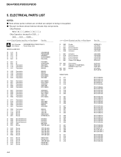
.... Chip Resistor RS1/_S___J,RS1/__S___J Chip Capacitor (except for CQS.....) CKS....., CCS....., CSZS..... =====Circuit Symbol and No.===Part Name Part No A Unit Number : CWM6082(DEH-P300/X1N/UC) Unit Name : Tuner Amp Unit MISCELLANEOUS IC 411 IC IC 451 IC IC 471 IC IC 472 IC IC 551 IC CA0008AM PML003AM... RS1/10S223J RS1/10S223J RS1/10S223J RS1/10S223J RS1/8S473J RD1/4PU221J RD1/4PU221J RS1/10S183J RS1/10S183J RS1/10S183J RS1/10S183J RS1/10S472J 44 DEH-P300,P3000,P200 5.
.... Chip Resistor RS1/_S___J,RS1/__S___J Chip Capacitor (except for CQS.....) CKS....., CCS....., CSZS..... =====Circuit Symbol and No.===Part Name Part No A Unit Number : CWM6082(DEH-P300/X1N/UC) Unit Name : Tuner Amp Unit MISCELLANEOUS IC 411 IC IC 451 IC IC 471 IC IC 472 IC IC 551 IC CA0008AM PML003AM... RS1/10S223J RS1/10S223J RS1/10S223J RS1/10S223J RS1/8S473J RD1/4PU221J RD1/4PU221J RS1/10S183J RS1/10S183J RS1/10S183J RS1/10S183J RS1/10S472J 44 DEH-P300,P3000,P200 5.
Service Manual
Page 52
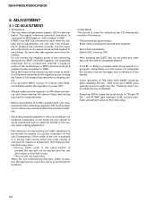
... 1 negative probe of the device. • Test mode starting procedure Reset while pressing the 4 and 6 keys together. • Test mode cancellation Switch ACC, back-up . DEH-P300,P3000,P200 6.
... 1 negative probe of the device. • Test mode starting procedure Reset while pressing the 4 and 6 keys together. • Test mode cancellation Switch ACC, back-up . DEH-P300,P3000,P200 6.
Service Manual
Page 82
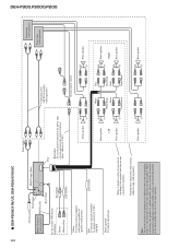
... ≠ Connecting cords with power regardless of this product may be different colors to the other products. DEH-P300,P3000,P200 82 - Red To electric terminal controlled by ignition switch (12 V DC) ON/OFF. DEH-P3000/X1N/UC, DEH-P200/X1N/UC Antenna jack This Product Multi-CD player (sold separately). When connecting this product to...
... ≠ Connecting cords with power regardless of this product may be different colors to the other products. DEH-P300,P3000,P200 82 - Red To electric terminal controlled by ignition switch (12 V DC) ON/OFF. DEH-P3000/X1N/UC, DEH-P200/X1N/UC Antenna jack This Product Multi-CD player (sold separately). When connecting this product to...


