Service Manual
Page 1
... series. Service DEH-P300/X1N/UC Manual MULTI-CD CONTROL HIGH POWER CD PLAYER WITH FM/AM TUNER DEH-P300 DEH-P3000 X1N/UC DEH-P200 X1N/UC ORDER NO. GENERAL INFORMATION 56 7.1 PARTS 56 7.1.1 IC 56 7.1.2 DISPLAY 63 7.2 DIAGNOSIS 64 7.2.1 DISASSEMBLY 64 7.2.2 TEST MODE 65 7.3 BLOCK DIAGRAM 69 8. See the separate manual CX-916(CRT2300) for the CD mechanism description, disassembly and circuit description. - PIONEER ELECTRONIC [EUROPE...
... series. Service DEH-P300/X1N/UC Manual MULTI-CD CONTROL HIGH POWER CD PLAYER WITH FM/AM TUNER DEH-P300 DEH-P3000 X1N/UC DEH-P200 X1N/UC ORDER NO. GENERAL INFORMATION 56 7.1 PARTS 56 7.1.1 IC 56 7.1.2 DISPLAY 63 7.2 DIAGNOSIS 64 7.2.1 DISASSEMBLY 64 7.2.2 TEST MODE 65 7.3 BLOCK DIAGRAM 69 8. See the separate manual CX-916(CRT2300) for the CD mechanism description, disassembly and circuit description. - PIONEER ELECTRONIC [EUROPE...
Service Manual
Page 2
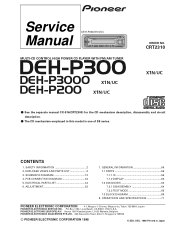
... manual. During disassembly, be sure to turn the power off since an internal IC might be taken to a qualified service ...changing the service pickup unit(see page 54). you are known to "Disassembly"(CX-916 Service Manual CRT2300). DEH-P300,P3000,P200 - CAUTION This service manual is plugged or unplugged. 3. Health & Safety Code Section 25249.6 - Improperly performed repairs can adversely affect the safety and reliability of the product and may void the warranty. CD Player Service Precautions 1. During replacement, handling precautions shall be destroyed when a connector...
... manual. During disassembly, be sure to turn the power off since an internal IC might be taken to a qualified service ...changing the service pickup unit(see page 54). you are known to "Disassembly"(CX-916 Service Manual CRT2300). DEH-P300,P3000,P200 - CAUTION This service manual is plugged or unplugged. 3. Health & Safety Code Section 25249.6 - Improperly performed repairs can adversely affect the safety and reliability of the product and may void the warranty. CD Player Service Precautions 1. During replacement, handling precautions shall be destroyed when a connector...
Service Manual
Page 3
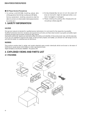
... table(2) (2) CONTRAST TABLE DEH-P300/X1N/UC, DEH-P3000/X1N/UC and DEH-P200/X1N/UC are not in our Master Spare Parts List. - Symbol and Description 14 Carton 15 Contain Box 20-1 Owner's Manual 20-2 Installation Manual * 20-3 Warranty Card DEH-P300/X1N/UC CHG3645 CHL3645 CRD2822 CRD2823 CRY1070 * 20-5 Card Not used for the following: Mark No. Description 1 Cord Assy * 2 Accessory...
... table(2) (2) CONTRAST TABLE DEH-P300/X1N/UC, DEH-P3000/X1N/UC and DEH-P200/X1N/UC are not in our Master Spare Parts List. - Symbol and Description 14 Carton 15 Contain Box 20-1 Owner's Manual 20-2 Installation Manual * 20-3 Warranty Card DEH-P300/X1N/UC CHG3645 CHL3645 CRD2822 CRD2823 CRY1070 * 20-5 Card Not used for the following: Mark No. Description 1 Cord Assy * 2 Accessory...
Service Manual
Page 12
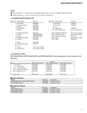
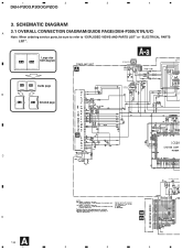
1 2 3 4 DEH-P300,P3000,P200 3. Large size A-a A-b SCH diagram A A-a IP BUS IN 4.3V 4.3V 4.3V 4.3V 4.3V A-a A-b Guide page B A-a A-b Detailed page IP BUS DRIVER 4.3V 4.3V 4.3V SO EL 4.3V 4.3V B DE C ANTENNA CABLE D A 12 1 2 3 VD REGULATOR 4 SCHEMATIC DIAGRAM 3.1 OVERALL CONNECTION DIAGRAM(GUIDE PAGE)(DEH-P300/X1N/UC) A Note: When ordering service parts, be sure to refer to "EXPLODED VIEWS AND PARTS LIST" or "ELECTRICAL PARTS LIST".
1 2 3 4 DEH-P300,P3000,P200 3. Large size A-a A-b SCH diagram A A-a IP BUS IN 4.3V 4.3V 4.3V 4.3V 4.3V A-a A-b Guide page B A-a A-b Detailed page IP BUS DRIVER 4.3V 4.3V 4.3V SO EL 4.3V 4.3V B DE C ANTENNA CABLE D A 12 1 2 3 VD REGULATOR 4 SCHEMATIC DIAGRAM 3.1 OVERALL CONNECTION DIAGRAM(GUIDE PAGE)(DEH-P300/X1N/UC) A Note: When ordering service parts, be sure to refer to "EXPLODED VIEWS AND PARTS LIST" or "ELECTRICAL PARTS LIST".
Service Manual
Page 34
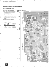
gram. 2. PCB CONNECTION DIAGRAM 4.1 TUNER AMP UNIT A NOTE FOR PCB DIAGRAMS 1. Viewpoint of PCB diagrams CORD ASSY Connector Capacitor SIDE A B P.C.Board Chip Part SIDE B C D CN701 D A 34 1 2 3 4 The parts mounted on this PCB A TUNER AMP UNIT include all necessary parts for respective destinations, be sure to check with the schematic dia- For further information for several destination. 1 2 3 4 DEH-P300,P3000,P200 4.
gram. 2. PCB CONNECTION DIAGRAM 4.1 TUNER AMP UNIT A NOTE FOR PCB DIAGRAMS 1. Viewpoint of PCB diagrams CORD ASSY Connector Capacitor SIDE A B P.C.Board Chip Part SIDE B C D CN701 D A 34 1 2 3 4 The parts mounted on this PCB A TUNER AMP UNIT include all necessary parts for respective destinations, be sure to check with the schematic dia- For further information for several destination. 1 2 3 4 DEH-P300,P3000,P200 4.
Service Manual
Page 44
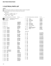
... Resistor RS1/_S___J,RS1/__S___J Chip Capacitor (except for CQS.....) CKS....., CCS....., CSZS..... =====Circuit Symbol and No.===Part Name Part No A Unit Number : CWM6082(DEH-P300/X1N/UC) Unit Name : Tuner Amp Unit MISCELLANEOUS IC 411 IC IC 451 IC IC 471 IC IC 472 IC IC 551 IC CA0008AM PML003AM M5282FP NJM4558MD ... RS1/8S473J RD1/4PU221J RD1/4PU221J RS1/10S183J RS1/10S183J RS1/10S183J RS1/10S183J RS1/10S472J 44 The part numbers shown below indicate chip components. DEH-P300,P3000,P200 5. Parts whose parts numbers are omitted are subject to being not supplied. - ELECTRICAL...
... Resistor RS1/_S___J,RS1/__S___J Chip Capacitor (except for CQS.....) CKS....., CCS....., CSZS..... =====Circuit Symbol and No.===Part Name Part No A Unit Number : CWM6082(DEH-P300/X1N/UC) Unit Name : Tuner Amp Unit MISCELLANEOUS IC 411 IC IC 451 IC IC 471 IC IC 472 IC IC 551 IC CA0008AM PML003AM M5282FP NJM4558MD ... RS1/8S473J RD1/4PU221J RD1/4PU221J RS1/10S183J RS1/10S183J RS1/10S183J RS1/10S183J RS1/10S472J 44 The part numbers shown below indicate chip components. DEH-P300,P3000,P200 5. Parts whose parts numbers are omitted are subject to being not supplied. - ELECTRICAL...
Service Manual
Page 52
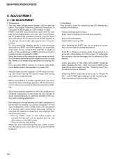
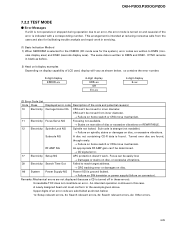
... to stabilize. • Since the protective systems in this , take special note of the device. • Test mode starting procedure Reset while pressing the 4 and 6 keys together. • Test mode cancellation Switch ACC, back-up . The signal reference potential, therefore, is used for repairs or adjustment, the following . ADJUSTMENT 6.1 CD ADJUSTMENT 1) Precautions • This unit uses a single power supply (+5V) for the reg- It...
... to stabilize. • Since the protective systems in this , take special note of the device. • Test mode starting procedure Reset while pressing the 4 and 6 keys together. • Test mode cancellation Switch ACC, back-up . The signal reference potential, therefore, is used for repairs or adjustment, the following . ADJUSTMENT 6.1 CD ADJUSTMENT 1) Precautions • This unit uses a single power supply (+5V) for the reg- It...
Service Manual
Page 56
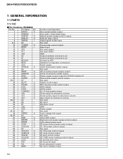
... power supply control output External relay output Test program mode input Not used Tuner power control output Reset input Not used (open) Not used (GND) GND Crystal oscillator connection pin Crystal oscillator connection pin Connect to VSS Capacitor for regulator connect pin Power supply Green illumination select output Not used A/D converter power supply output Amber illumination select output Power supply control output for IP BUS interface IC Slave power supply control output Not used System mute output RDS decoder power select output LOCL output LOCH output PLL IC chip enable output Clock...
... power supply control output External relay output Test program mode input Not used Tuner power control output Reset input Not used (open) Not used (GND) GND Crystal oscillator connection pin Crystal oscillator connection pin Connect to VSS Capacitor for regulator connect pin Power supply Green illumination select output Not used A/D converter power supply output Amber illumination select output Power supply control output for IP BUS interface IC Slave power supply control output Not used System mute output RDS decoder power select output LOCL output LOCH output PLL IC chip enable output Clock...
Service Manual
Page 57
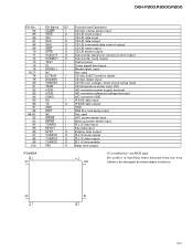
... O TUNPCE O PEE O Function and Operation CD disc clamp sense input CD LSI clock output CD LSI data input CD LSI data output CD LSI command/data control output CD LSI reset output CD LSI strobe output Sub woofer electronic volume control output Sub woofer mute output Test terminal Tuner signal level input Model select input Not used CD disc EJECT position detect CD disc detect input CD VD over voltage / short-circuit sense input CD temperature sense input (CD) A/D converter power supply terminal A/D converter...
... O TUNPCE O PEE O Function and Operation CD disc clamp sense input CD LSI clock output CD LSI data input CD LSI data output CD LSI command/data control output CD LSI reset output CD LSI strobe output Sub woofer electronic volume control output Sub woofer mute output Test terminal Tuner signal level input Model select input Not used CD disc EJECT position detect CD disc detect input CD VD over voltage / short-circuit sense input CD temperature sense input (CD) A/D converter power supply terminal A/D converter...

Service Manual
Page 58
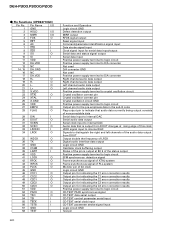
... 21 1 Function and Operation GND Crystal oscillator connection pin Crystal oscillator connection pin Not used Connect to GND Not used Key data output Display data input Remote control pulse input Not used Key data input Key strobe output VDD LCD segment output LCD common output LCD voltage input Power supply terminal BR9010FV 80 NC 1 8 WC 40 PAL005A 41 60 VCC 2 CS : Chip select input 7 SK : Serial data clock input DI : Serial data input DO : Serial data output CS...
... 21 1 Function and Operation GND Crystal oscillator connection pin Crystal oscillator connection pin Not used Connect to GND Not used Key data output Display data input Remote control pulse input Not used Key data input Key strobe output VDD LCD segment output LCD common output LCD voltage input Power supply terminal BR9010FV 80 NC 1 8 WC 40 PAL005A 41 60 VCC 2 CS : Chip select input 7 SK : Serial data clock input DI : Serial data input DO : Serial data output CS...
Service Manual
Page 60
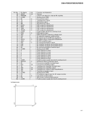
... C2 error correction results Output pin for indicating the C2 error correction results Output pin for indicating the C2 error correction results Positive power supply terminal to logic circuit CD-TEXT PACK synchronous signal CD-TEXT data serial output CD-TEXT control parameter serial input CD-TEXT serial clock input CD-TEXT parameter strobe signal input Logic circuit GND Test pin O 20 L- DEH-P300,P3000,P200 - Pin Functions (UPD63710GC) Pin...
... C2 error correction results Output pin for indicating the C2 error correction results Output pin for indicating the C2 error correction results Positive power supply terminal to logic circuit CD-TEXT PACK synchronous signal CD-TEXT data serial output CD-TEXT control parameter serial input CD-TEXT serial clock input CD-TEXT parameter strobe signal input Logic circuit GND Test pin O 20 L- DEH-P300,P3000,P200 - Pin Functions (UPD63710GC) Pin...
Service Manual
Page 61
...not use select for internal RF amplifier Analog circuit GND O Focus drive output O Tracking drive output O Sled drive output O Spindle drive output O DAC output for adjustment O DAC output for adjustment O DAC output for adjustment O DAC output for adjustment Power supply terminal to analog circuit O EFM signal output I EFM comparator reference voltage input 3T detection capacitor additional pin I RF signal input for EFM data regulation O RF signal output of after gain adjustment I RF-AGC amplifier input O RF summing amplifier output RF amplifier equalizer parts...
...not use select for internal RF amplifier Analog circuit GND O Focus drive output O Tracking drive output O Sled drive output O Spindle drive output O DAC output for adjustment O DAC output for adjustment O DAC output for adjustment O DAC output for adjustment Power supply terminal to analog circuit O EFM signal output I EFM comparator reference voltage input 3T detection capacitor additional pin I RF signal input for EFM data regulation O RF signal output of after gain adjustment I RF-AGC amplifier input O RF summing amplifier output RF amplifier equalizer parts...
Service Manual
Page 65
... damages on connector). Error Messages If a CD is turned on disc. utes display area) and DSEC (seconds display area). Turned over disc are written to an error, the error mode is not operative or stopped during operation due to DMIN (min- Focus can 't be determined. → CD signal error. 17 Electricity Setup NG APC protection doesn't work in blank as before. 2) Head unit display examples Depending on home switch or CRG...
... damages on connector). Error Messages If a CD is turned on disc. utes display area) and DSEC (seconds display area). Turned over disc are written to an error, the error mode is not operative or stopped during operation due to DMIN (min- Focus can 't be determined. → CD signal error. 17 Electricity Setup NG APC protection doesn't work in blank as before. 2) Head unit display examples Depending on home switch or CRG...
Service Manual
Page 66
... . Sub-code was activated. → Damages/stains on disc, vibrations or failure on or off focus, spindle unlocking, unreadable sub-code, or sound skipping occurs after setup, its cause and time occurred (in the normal mode. 66 T.Close (AGC performed) Scan - /parameter display switching 2 RF AMP gain switching Parameter display switching Mode - /T.BAL adjustment/T.Open 3 To power on servo. 43 Electricity Sound skipping detected. Note: Mechanical errors during aging are displayed. FWD...
... . Sub-code was activated. → Damages/stains on disc, vibrations or failure on or off focus, spindle unlocking, unreadable sub-code, or sound skipping occurs after setup, its cause and time occurred (in the normal mode. 66 T.Close (AGC performed) Scan - /parameter display switching 2 RF AMP gain switching Parameter display switching Mode - /T.BAL adjustment/T.Open 3 To power on servo. 43 Electricity Sound skipping detected. Note: Mechanical errors during aging are displayed. FWD...
Service Manual
Page 74
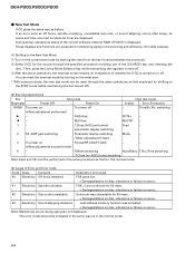
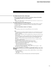
... a different length of multiCD players such as "CDX-P630S" which you switch displays when disc titles have not been input, "NO TITLE" is displayed. DEH-P300,P3000,P200 Basic Operation Basic Operation of Multi-CD Player This product can select between Track Search or Fast forward/Reverse by pressing the 2/3 button for 2 seconds.) 74 Switching the Multi-CD Player Using a multiple connection adapter lets you connect up to three Multi...
... a different length of multiCD players such as "CDX-P630S" which you switch displays when disc titles have not been input, "NO TITLE" is displayed. DEH-P300,P3000,P200 Basic Operation Basic Operation of Multi-CD Player This product can select between Track Search or Fast forward/Reverse by pressing the 2/3 button for 2 seconds.) 74 Switching the Multi-CD Player Using a multiple connection adapter lets you connect up to three Multi...
Service Manual
Page 75
... presence of information stops part way through. DEH-P300,P3000,P200 Disc Number Search (for 2 seconds or longer. Note: • When a 12-Disc Multi-CD Player is selected for playback. Just press the number corresponding to the disc you want to listen to 6 buttons for 6-Disc, 12-Disc types) • You can use the "Ejecting a Single Disc", "Frequency Play", "Music Group Play" or "ABC Disc Title Search" functions with this happens, reading...
... presence of information stops part way through. DEH-P300,P3000,P200 Disc Number Search (for 2 seconds or longer. Note: • When a 12-Disc Multi-CD Player is selected for playback. Just press the number corresponding to the disc you want to listen to 6 buttons for 6-Disc, 12-Disc types) • You can use the "Ejecting a Single Disc", "Frequency Play", "Music Group Play" or "ABC Disc Title Search" functions with this happens, reading...
Service Manual
Page 77
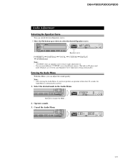
... press changes the Mode ... 2. Operate a mode. 3. DEH-P300,P3000,P200 Audio Adjustment Selecting the Equalizer Curve You can switch between Equalizer curves. • Move the EQ button up or down to the same Equalizer Curve Adjustment setting automatically.) Entering the Audio Menu With this Menu, you can create different "CUSTOM" curves for different sources. (The built-in the Audio Menu. Equalizer curve POWERFUL += NATURAL += VOCAL += CUSTOM += EQ FLAT += SUPER BASS Note: • "CUSTOM" stores an equalizer...
... press changes the Mode ... 2. Operate a mode. 3. DEH-P300,P3000,P200 Audio Adjustment Selecting the Equalizer Curve You can switch between Equalizer curves. • Move the EQ button up or down to the same Equalizer Curve Adjustment setting automatically.) Entering the Audio Menu With this Menu, you can create different "CUSTOM" curves for different sources. (The built-in the Audio Menu. Equalizer curve POWERFUL += NATURAL += VOCAL += CUSTOM += EQ FLAT += SUPER BASS Note: • "CUSTOM" stores an equalizer...
Service Manual
Page 78
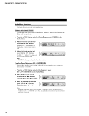
DEH-P300,P3000,P200 Audio Menu Functions The Audio Menu features the following functions. Press the AUDIO button and select Fader/Balance mode (FADER) in use. Adjust left to right. Note: • "FADER 0" is displayed as it moves from front to adjust with the 5/∞ buttons. Boost or attenuate the selected band with the 2/3 buttons. "BAL R 9" is the proper setting when 2 speakers are memorized in memory as desired. "-6". Press the AUDIO button and select the Equalizer mode (EQ-LOW...
DEH-P300,P3000,P200 Audio Menu Functions The Audio Menu features the following functions. Press the AUDIO button and select Fader/Balance mode (FADER) in use. Adjust left to right. Note: • "FADER 0" is displayed as it moves from front to adjust with the 5/∞ buttons. Boost or attenuate the selected band with the 2/3 buttons. "BAL R 9" is the proper setting when 2 speakers are memorized in memory as desired. "-6". Press the AUDIO button and select the Equalizer mode (EQ-LOW...
Service Manual
Page 81
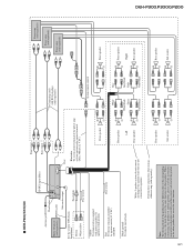
... connect anything to the speaker leads that serves the same function. + Rear speaker ≠ + Sub-woofer ≠ Connecting cords with power regardless of this product to speakers. + Front speaker ≠ + Front speaker ≠ Left + Rear speaker ≠ Perform these connections when using a different amp (sold separately) IP-BUS cable Sub-woofer output See the section "DFS Alarm Installation". DEH-P300,P3000,P200 81 - Note: The electrical leads of ignition switch position. DEH-P300/X1N/UC Front output IP-BUS input (Blue) Antenna...
... connect anything to the speaker leads that serves the same function. + Rear speaker ≠ + Sub-woofer ≠ Connecting cords with power regardless of this product to speakers. + Front speaker ≠ + Front speaker ≠ Left + Rear speaker ≠ Perform these connections when using a different amp (sold separately) IP-BUS cable Sub-woofer output See the section "DFS Alarm Installation". DEH-P300,P3000,P200 81 - Note: The electrical leads of ignition switch position. DEH-P300/X1N/UC Front output IP-BUS input (Blue) Antenna...
Service Manual
Page 82
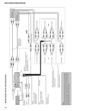
... output Fuse Blue/white To system control terminal of this product may be different colors to speakers. + Front speaker ≠ + Front speaker ≠ Left + Rear speaker ≠ Perform these connections when using a different amp (sold separately). Black (ground) To vehicle (metal) body. When connecting this product to another product, please read the instruction manual for each product carefully and then connect each lead of the power amp or Auto-antenna relay control...
... output Fuse Blue/white To system control terminal of this product may be different colors to speakers. + Front speaker ≠ + Front speaker ≠ Left + Rear speaker ≠ Perform these connections when using a different amp (sold separately). Black (ground) To vehicle (metal) body. When connecting this product to another product, please read the instruction manual for each product carefully and then connect each lead of the power amp or Auto-antenna relay control...


