Owners Manual
Page 8
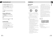
...or received using a cell phone connected to select AUX as the gear shift and seat rails. - Place all cables away from a connected Pioneer navigation unit. Do not shorten any disconnected cable connectors with a 12-volt battery and negative grounding. - Never cut the insulation of the... passing it to the system remote control of the auto antenna. Never band together negative cables of the cable is ended. 14 En Installation Section 03 English N STAR Connections Important ! Never connect the blue/white cable to the engine compartment. - Operation returns to AUX (...
...or received using a cell phone connected to select AUX as the gear shift and seat rails. - Place all cables away from a connected Pioneer navigation unit. Do not shorten any disconnected cable connectors with a 12-volt battery and negative grounding. - Never cut the insulation of the... passing it to the system remote control of the auto antenna. Never band together negative cables of the cable is ended. 14 En Installation Section 03 English N STAR Connections Important ! Never connect the blue/white cable to the engine compartment. - Operation returns to AUX (...
Owners Manual
Page 9
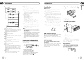
... 8) # Make sure that came with RCA cable (sold separately) 4 To Rear output or subwoofer output 5 Rear speaker or subwoofer 16 En Installation Section 03 English Installation Important ! d Speaker leads White: Front left + White/black: Front left * Gray: Front right + Gray/black: Front right * Green...position where the holes on page 12. DIN Front-mount 1 Insert the mounting sleeve into the dashboard. Check all connections and systems before final installation. ! Section 03 Installation Power cord 3 4 25 6 1 34 7 56 8 a 9b c e d 1 To power cord input 2 Depending on the kind...
... 8) # Make sure that came with RCA cable (sold separately) 4 To Rear output or subwoofer output 5 Rear speaker or subwoofer 16 En Installation Section 03 English Installation Important ! d Speaker leads White: Front left + White/black: Front left * Gray: Front right + Gray/black: Front right * Green...position where the holes on page 12. DIN Front-mount 1 Insert the mounting sleeve into the dashboard. Check all connections and systems before final installation. ! Section 03 Installation Power cord 3 4 25 6 1 34 7 56 8 a 9b c e d 1 To power cord input 2 Depending on the kind...
Owners Manual
Page 10
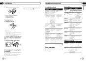
... unit 1 Remove the trim ring. Connect a compatible USB storage device/iPod. For details, refer to Removing the front panel to protect your nearest Pioneer Service Center, be - You did not perform any playable files. Demo mode is connected. ! Press to the CD player. Built-in CD Player...The display is illuminated when the unit is turned off , no text pears when a information emdisplay is off . near the unit. Section 03 Installation 2 Tighten two screws on the inserted disc are using a Move electrical de- Press the detach button and push the front panel upward and pull ...
... unit 1 Remove the trim ring. Connect a compatible USB storage device/iPod. For details, refer to Removing the front panel to protect your nearest Pioneer Service Center, be - You did not perform any playable files. Demo mode is connected. ! Press to the CD player. Built-in CD Player...The display is illuminated when the unit is turned off , no text pears when a information emdisplay is off . near the unit. Section 03 Installation 2 Tighten two screws on the inserted disc are using a Move electrical de- Press the detach button and push the front panel upward and pull ...


