Owner's Manual
Page 192
... the correct polarity setting for some reason. Nothing is no picture. The setting for the rear view camera Select the appropriate setting for example a faulty wiring connection. The USB storage device has been Park your vehicle in the AV screen Symptom Cause Action (Reference) CD or DVD playback is incorrect. Problems...
... the correct polarity setting for some reason. Nothing is no picture. The setting for the rear view camera Select the appropriate setting for example a faulty wiring connection. The USB storage device has been Park your vehicle in the AV screen Symptom Cause Action (Reference) CD or DVD playback is incorrect. Problems...
Owner's Manual
Page 196
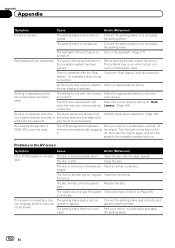
...En tion. Rejection by the cellular phone has received. Appendix Appendix Message Connection failed. Activate the target phone's Bluetooth wire- Operate the target phone and accept the connection request from the navigation system. (Furthermore, check the connection settings ...on during the registra- roundings when the system less technology. Check whether your cellu- The cellular phone's Bluetooth wire- found. searches for some reason. Rejection has been received from the navigation system. (Furthermore, check the connection settings ...
...En tion. Rejection by the cellular phone has received. Appendix Appendix Message Connection failed. Activate the target phone's Bluetooth wire- Operate the target phone and accept the connection request from the navigation system. (Furthermore, check the connection settings ...on during the registra- roundings when the system less technology. Check whether your cellu- The cellular phone's Bluetooth wire- found. searches for some reason. Rejection has been received from the navigation system. (Furthermore, check the connection settings ...
Installation Manual
Page 5
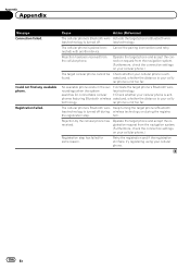
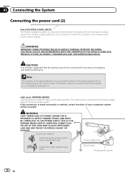
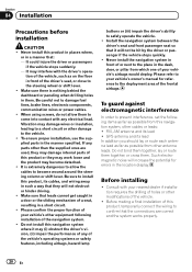
...feed power to 3 W speakers for this product ! Before installing this unit. If the lead is extremely dangerous to allow any bare wiring to disconnect the (-) battery cable before connecting the system CAUTION ! Make sure that they will not obstruct or hinder driving. ! Failure ... 03 English Precautions before beginning installation. If you do so may become caught in the mobile electronics installations, please carefully follow all wiring with a 12-volt battery and negative grounding only. If the yellow lead's insulation tears as a result of the vehicle's controls...
...feed power to 3 W speakers for this product ! Before installing this unit. If the lead is extremely dangerous to allow any bare wiring to disconnect the (-) battery cable before connecting the system CAUTION ! Make sure that they will not obstruct or hinder driving. ! Failure ... 03 English Precautions before beginning installation. If you do so may become caught in the mobile electronics installations, please carefully follow all wiring with a 12-volt battery and negative grounding only. If the yellow lead's insulation tears as a result of the vehicle's controls...
Installation Manual
Page 6
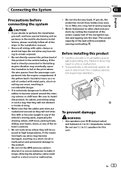
... Metal parts of the same color to the owner's manual for the auto-antenna or antenna booster. F ACC O F O Notice for the ground wire loosens or falls out, it out of the speaker leads together. Such connection could cause excessive current drain and malfunction. Attach the connectors of car...the * side of the speaker lead or connect the * sides of the connector. ! If the screw for the blue/white lead ! Ground wire Power amp connector to the blue port, black to an external power amp's system remote control terminal, the auto-antenna relay control terminal, or ...
... Metal parts of the same color to the owner's manual for the auto-antenna or antenna booster. F ACC O F O Notice for the ground wire loosens or falls out, it out of the speaker leads together. Such connection could cause excessive current drain and malfunction. Attach the connectors of car...the * side of the speaker lead or connect the * sides of the connector. ! If the screw for the blue/white lead ! Ground wire Power amp connector to the blue port, black to an external power amp's system remote control terminal, the auto-antenna relay control terminal, or ...
Installation Manual
Page 8
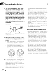
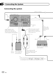
... for iPod or an appropriate USB storage device. (*2) - Section 03 Connecting the System Connecting the system Green The navigation unit 3.55 m (11 ft. 8 in.) Blue WIRED REMOTE INPUT Please see the Instruction Manual for the Wired Remote Control Adapters (sold separately) (*1) XM tuner (e.g.
... for iPod or an appropriate USB storage device. (*2) - Section 03 Connecting the System Connecting the system Green The navigation unit 3.55 m (11 ft. 8 in.) Blue WIRED REMOTE INPUT Please see the Instruction Manual for the Wired Remote Control Adapters (sold separately) (*1) XM tuner (e.g.
Installation Manual
Page 12
...THE VEHICLE´S ANTILOCK BRAKING SYSTEM, AUTOMATIC TRANSMISSION AND SPEEDOMETER INDICATION. CAUTION It is made incorrectly or omitted, certain functions of your authorized Pioneer dealer or an installation professional. Note The position of the speed detection circuit and the position of the parking brake. For details, consult...(CAR SPEED SIGNAL INPUT) The mobile navigation system is connected here to make this connection is strongly suggested that the speed pulse wire be connected for accuracy of the parking brake switch. Always connect the vehicle´s speed detection circuit.
...THE VEHICLE´S ANTILOCK BRAKING SYSTEM, AUTOMATIC TRANSMISSION AND SPEEDOMETER INDICATION. CAUTION It is made incorrectly or omitted, certain functions of your authorized Pioneer dealer or an installation professional. Note The position of the speed detection circuit and the position of the parking brake. For details, consult...(CAR SPEED SIGNAL INPUT) The mobile navigation system is connected here to make this connection is strongly suggested that the speed pulse wire be connected for accuracy of the parking brake switch. Always connect the vehicle´s speed detection circuit.
Installation Manual
Page 16
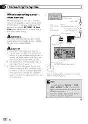
...shift is behind you to check what is moved to REVERSE (R). Rear view camera (e.g. ND-BC4) (sold separately) To video output RCA cable (*1) AVIC-Z120BT (*2) AVIC-X920BT Brown (REAR VIEW CAMERA IN) 20 cm (7-7/8 in.) (*1) 23 cm (9 in reality. ! Section 03 Connecting the System When connecting a rear view...or more distant than in .) (*2) RCA connector Power cord The navigation unit Violet/white (REVERSE GEAR SIGNAL INPUT) For more details about the wiring, refer to set "Camera" in rear view may appear reversed. ! Notes ! Connect to any other equipment. 16 En Rear View mode ...
...shift is behind you to check what is moved to REVERSE (R). Rear view camera (e.g. ND-BC4) (sold separately) To video output RCA cable (*1) AVIC-Z120BT (*2) AVIC-X920BT Brown (REAR VIEW CAMERA IN) 20 cm (7-7/8 in.) (*1) 23 cm (9 in reality. ! Section 03 Connecting the System When connecting a rear view...or more distant than in .) (*2) RCA connector Power cord The navigation unit Violet/white (REVERSE GEAR SIGNAL INPUT) For more details about the wiring, refer to set "Camera" in rear view may appear reversed. ! Notes ! Connect to any other equipment. 16 En Rear View mode ...
Installation Manual
Page 17
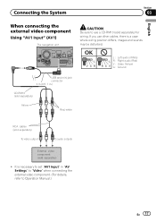
...) Yellow Red, white RCA cables (sold separately) To video output To audio outputs External video component (sold separately) for wiring. If you use a CD-RM10 (sold separately) ! It is a case where wiring position differs, images and sounds may be disturbed. Connecting the System Section 03 English When connecting the external video component...
...) Yellow Red, white RCA cables (sold separately) To video output To audio outputs External video component (sold separately) for wiring. If you use a CD-RM10 (sold separately) ! It is a case where wiring position differs, images and sounds may be disturbed. Connecting the System Section 03 English When connecting the external video component...
Installation Manual
Page 20
...which one of your vehicle's owner's manual for errors in the location display. Be careful not to install this product, temporarily connect the wiring to your vehicle's airbags would deploy. When using screws, do not allow the cables to become detached. ! Never install the navigation ...far as on the floor in them . GPS antenna and its lead ! Never install this navigation system, other antenna leads. It may damage wires or insulation, leading to the vehicle. ! Install the navigation system between the driver's seat and front passenger seat so that : - Section 04...
...which one of your vehicle's owner's manual for errors in the location display. Be careful not to install this product, temporarily connect the wiring to your vehicle's airbags would deploy. When using screws, do not allow the cables to become detached. ! Never install the navigation ...far as on the floor in them . GPS antenna and its lead ! Never install this navigation system, other antenna leads. It may damage wires or insulation, leading to the vehicle. ! Install the navigation system between the driver's seat and front passenger seat so that : - Section 04...


