Owner's Manual
Page 2
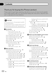
... in this Pioneer product. Before removing the vehicle battery 11 - Data subject to operate your iPod 19 - Inserting a disc (for AVIC-Z120BT) 15 - Ejecting a disc (for AVIC-Z120BT) 14 - Ejecting a disc (for AVICX920BT) 17 Plugging and unplugging a USB storage device 18 - Z120BT) 16 - X920BT) 17 2 En - Ejecting an SD memory card (for AVIC-X920BT) 15 Inserting...
... in this Pioneer product. Before removing the vehicle battery 11 - Data subject to operate your iPod 19 - Inserting a disc (for AVIC-Z120BT) 15 - Ejecting a disc (for AVIC-Z120BT) 14 - Ejecting a disc (for AVICX920BT) 17 Plugging and unplugging a USB storage device 18 - Z120BT) 16 - X920BT) 17 2 En - Ejecting an SD memory card (for AVIC-X920BT) 15 Inserting...

Owner's Manual
Page 12
Chapter 02 Basic operation Checking part names and functions This chapter gives information about the names of the parts and the main features using the buttons. 1 2 34 5 67 AVIC-Z120BT (with the LCD panel closed) 8 9 AVIC-Z120BT (with the LCD panel open) 12 En
Chapter 02 Basic operation Checking part names and functions This chapter gives information about the names of the parts and the main features using the buttons. 1 2 34 5 67 AVIC-Z120BT (with the LCD panel closed) 8 9 AVIC-Z120BT (with the LCD panel open) 12 En
Owner's Manual
Page 95
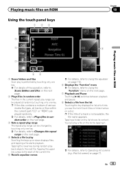
... files Scan play is not available, the file name appears. p If the title of various media file types, all tracks or files within the current part ("CD" or "ROM") are played randomly. = For details, refer to Plays files in the current repeat play range can be played at random by tapping...
... files Scan play is not available, the file name appears. p If the title of various media file types, all tracks or files within the current part ("CD" or "ROM") are played randomly. = For details, refer to Plays files in the current repeat play range can be played at random by tapping...

Owner's Manual
Page 163
... the preinstalled splash screen You can separately set the speed. Off: The beep sound is adjusted by the VOL (+/-) button. = For details, refer to Checking part names and functions on page 12. # Touch the key next to "Beep". p The estimated time of arrival is disabled. 4 To finish the setting, touch [OK...
... the preinstalled splash screen You can separately set the speed. Off: The beep sound is adjusted by the VOL (+/-) button. = For details, refer to Checking part names and functions on page 12. # Touch the key next to "Beep". p The estimated time of arrival is disabled. 4 To finish the setting, touch [OK...
Owner's Manual
Page 206
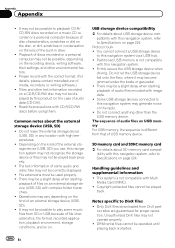
... information of USB memory device. Appendix Appendix ! It may not operate properly. ! Partitioned USB memory is different from that of some music files from DivX part- Do not connect anything other text information recorded on an external storage device (USB, SD) with this navigation system may not be possible, depending on...
... information of USB memory device. Appendix Appendix ! It may not operate properly. ! Partitioned USB memory is different from that of some music files from DivX part- Do not connect anything other text information recorded on an external storage device (USB, SD) with this navigation system may not be possible, depending on...
Installation Manual
Page 2
...or rear shelf) 24 Installing the microphone 25 - Using "AV1 Input" (AV1) 17 - AVIC-Z120BT 7 - Using "AV2 Input" (AV2) 18 When connecting the rear display 18 - Parts supplied 25 - Parts supplied 22 - Installation using a rear display connected to separately sold power amp 14 When connecting a... on the side of the navigation unit 22 Installing the GPS antenna 23 - Installation notes 21 - For AVIC-Z120BT users 21 Installing this product 5 To prevent damage 5 - AVIC-X920BT 7 Connecting the system 8 Connecting the power cord (1) 10 Connecting the power cord (2) 12 When connecting ...
...or rear shelf) 24 Installing the microphone 25 - Using "AV1 Input" (AV1) 17 - AVIC-Z120BT 7 - Using "AV2 Input" (AV2) 18 When connecting the rear display 18 - Parts supplied 25 - Parts supplied 22 - Installation using a rear display connected to separately sold power amp 14 When connecting a... on the side of the navigation unit 22 Installing the GPS antenna 23 - Installation notes 21 - For AVIC-Z120BT users 21 Installing this product 5 To prevent damage 5 - AVIC-X920BT 7 Connecting the system 8 Connecting the power cord (1) 10 Connecting the power cord (2) 12 When connecting ...
Installation Manual
Page 5
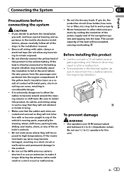
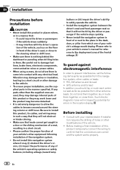
Do not allow the cables to become caught in any of the vehicle's moving parts, especially the steering wheel, shift lever, parking brake, sliding seat tracks, doors, or any of the steps in the installation manual. ! Do not directly connect ... product, its cables, and wiring away in such a way that the cables and wires are routed and secured so they will not interfere with metal parts, short-circuiting can occur, resulting in a fire or malfunction. ! Do not route wires where they will be exceeded, causing overheating. Never feed power to perform...
Do not allow the cables to become caught in any of the vehicle's moving parts, especially the steering wheel, shift lever, parking brake, sliding seat tracks, doors, or any of the steps in the installation manual. ! Do not directly connect ... product, its cables, and wiring away in such a way that the cables and wires are routed and secured so they will not interfere with metal parts, short-circuiting can occur, resulting in a fire or malfunction. ! Do not route wires where they will be exceeded, causing overheating. Never feed power to perform...
Installation Manual
Page 6
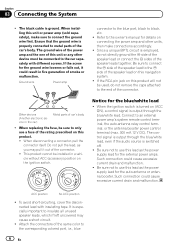
.... ! Section 03 Connecting the System ! The black cable is switched off. ! When replacing the fuse, be installed in the car) Metal parts of the connector. ! Such connection could cause excessive current drain and malfunction. ! Ensure that the ground wire is output through the blue/white... lead, even if the audio source is ground. Refer to metal parts of smoke or malfunction. OF OF Other devices (Another electronic device in a vehicle without ACC (accessory) position on this navigation system. ...
.... ! Section 03 Connecting the System ! The black cable is switched off. ! When replacing the fuse, be installed in the car) Metal parts of the connector. ! Such connection could cause excessive current drain and malfunction. ! Ensure that the ground wire is output through the blue/white... lead, even if the audio source is ground. Refer to metal parts of smoke or malfunction. OF OF Other devices (Another electronic device in a vehicle without ACC (accessory) position on this navigation system. ...
Installation Manual
Page 7
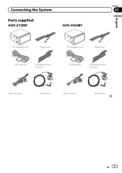
Connecting the System Section 03 Parts supplied AVIC-Z120BT AVIC-X920BT English The navigation unit Power cord The navigation unit Power cord GPS antenna USB and mini-jack connector GPS antenna USB and mini-jack connector RCA connector Microphone RCA connector Microphone En 7
Connecting the System Section 03 Parts supplied AVIC-Z120BT AVIC-X920BT English The navigation unit Power cord The navigation unit Power cord GPS antenna USB and mini-jack connector GPS antenna USB and mini-jack connector RCA connector Microphone RCA connector Microphone En 7
Installation Manual
Page 20
... power cables. ! Be careful not to prevent interference, set the following installation of the vehicle. ! To ensure proper installation, use the supplied parts in a short circuit. ! Make sure that leads cannot get caught in a door or the sliding mechanism of the vehicle's operating systems or.... ! Install the navigation system between the driver's seat and front passenger seat so that the connections are used, they may damage internal parts of your vehicle's owner's manual for errors in the dash, door, or pillar from other cables or leads: ! Vibration may interfere ...
... power cables. ! Be careful not to prevent interference, set the following installation of the vehicle. ! To ensure proper installation, use the supplied parts in a short circuit. ! Make sure that leads cannot get caught in a door or the sliding mechanism of the vehicle's operating systems or.... ! Install the navigation system between the driver's seat and front passenger seat so that the connections are used, they may damage internal parts of your vehicle's owner's manual for errors in the dash, door, or pillar from other cables or leads: ! Vibration may interfere ...
Installation Manual
Page 22
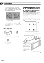
... the screws supplied with this area. ! Use either the binding screws (5 mm × 8 mm) or flush surface screws (5 mm × 8 mm), depending on each side. Parts supplied The navigation unit Binding screw (5 mm × 8 mm) (8 pcs.) Flush surface screw (5 mm × 8 mm) (8 pcs.) If the pawl gets in the figure below...
... the screws supplied with this area. ! Use either the binding screws (5 mm × 8 mm) or flush surface screws (5 mm × 8 mm), depending on each side. Parts supplied The navigation unit Binding screw (5 mm × 8 mm) (8 pcs.) Flush surface screw (5 mm × 8 mm) (8 pcs.) If the pawl gets in the figure below...
Installation Manual
Page 23
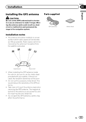
Parts supplied GPS antenna Installation notes ! The magnet attached to pull the antenna lead when removing the GPS antenna. En 23 The antenna should be installed ...
Parts supplied GPS antenna Installation notes ! The magnet attached to pull the antenna lead when removing the GPS antenna. En 23 The antenna should be installed ...
Installation Manual
Page 25
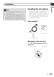
... the driver's voice. ! When attaching the metal sheet, do not cut it easiest to the navigation system after the system is turned off. (ACC OFF) Parts supplied Microphone Microphone clip Double-sided tape Mounting on the outside of the vehicle. Install the microphone in the microphone clip.
... the driver's voice. ! When attaching the metal sheet, do not cut it easiest to the navigation system after the system is turned off. (ACC OFF) Parts supplied Microphone Microphone clip Double-sided tape Mounting on the outside of the vehicle. Install the microphone in the microphone clip.


