Owner's Manual
Page 3
... 57 Adjusting the response positions of the touch panels (Touch Panel Calibration) 57 Using an AUX source 58 Using an external unit 58 Installation Connecting the units 60 Installation 68 Additional Information Troubleshooting 69 Error messages 71 Understanding messages 74 Indicator list 75 Handling guidelines 76 Compressed audio compatibility (disc, USB) 78...
... 57 Adjusting the response positions of the touch panels (Touch Panel Calibration) 57 Using an AUX source 58 Using an external unit 58 Installation Connecting the units 60 Installation 68 Additional Information Troubleshooting 69 Error messages 71 Understanding messages 74 Indicator list 75 Handling guidelines 76 Compressed audio compatibility (disc, USB) 78...
Owner's Manual
Page 4
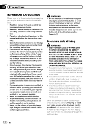
...vehicles. To ensure safe driving WARNING ! Section 01 Precautions IMPORTANT SAFEGUARDS Please read and understood the operating instructions. 5 Do not install the display where it may be illegal. To avoid the risk of damage and injury and the potential violation of your display...equipment and automotive accessories may (i) obstruct the driver's vision, (ii) impair the performance of any of your vehicle. Do not attempt to install or service your display. 2 Keep this manual handy as a reference for operating procedures and safety information. 3 Pay close attention to safely ...
...vehicles. To ensure safe driving WARNING ! Section 01 Precautions IMPORTANT SAFEGUARDS Please read and understood the operating instructions. 5 Do not install the display where it may be illegal. To avoid the risk of damage and injury and the potential violation of your display...equipment and automotive accessories may (i) obstruct the driver's vision, (ii) impair the performance of any of your vehicle. Do not attempt to install or service your display. 2 Keep this manual handy as a reference for operating procedures and safety information. 3 Pay close attention to safely ...
Owner's Manual
Page 5
WARNING NEVER install the rear display in motion, there is an interlock system that the edges of this unit to use the functions described above while driving, they ...
WARNING NEVER install the rear display in motion, there is an interlock system that the edges of this unit to use the functions described above while driving, they ...
Owner's Manual
Page 8
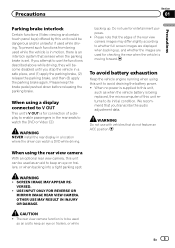
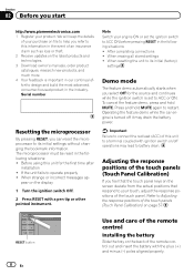
... insert the battery with the plus (+) and minus (-) poles aligned properly. RESET button 8 En Use and care of the remote control Installing the battery Slide the tray on the display 1 Turn the ignition switch OFF. 2 Press RESET with ignition switch on the screen deviate ... 2 Receive updates on page 57. Before using this information in the industry. Section 02 Before you select Off for the first time after installation ! Refer to ACC ON before pressing RESET in the following situations: ! Note Switch your product. After completing connections ! When strange or incorrect...
... insert the battery with the plus (+) and minus (-) poles aligned properly. RESET button 8 En Use and care of the remote control Installing the battery Slide the tray on the display 1 Turn the ignition switch OFF. 2 Press RESET with ignition switch on the screen deviate ... 2 Receive updates on page 57. Before using this information in the industry. Section 02 Before you select Off for the first time after installation ! Refer to ACC ON before pressing RESET in the following situations: ! Note Switch your product. After completing connections ! When strange or incorrect...
Owner's Manual
Page 9
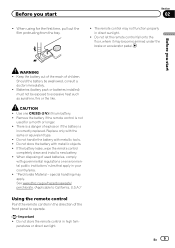
Batteries (battery pack or batteries installed) must not be swallowed, consult a doctor immediately. ! Remove the battery if the remote control is incorrectly replaced. There is a danger of the front panel to ... battery is not used batteries, comply with metallic objects. ! Use one CR2025 (3 V) lithium battery. ! If the battery leaks, wipe the remote control completely clean and install a new battery. ! See www.dtsc.ca.gov/hazardouswaste/ perchlorate. (Applicable to excessive heat such as sunshine, fire or the like. Before you start WARNING ! Do...
Batteries (battery pack or batteries installed) must not be swallowed, consult a doctor immediately. ! Remove the battery if the remote control is incorrectly replaced. There is a danger of the front panel to ... battery is not used batteries, comply with metallic objects. ! Use one CR2025 (3 V) lithium battery. ! If the battery leaks, wipe the remote control completely clean and install a new battery. ! See www.dtsc.ca.gov/hazardouswaste/ perchlorate. (Applicable to excessive heat such as sunshine, fire or the like. Before you start WARNING ! Do...
Owner's Manual
Page 54
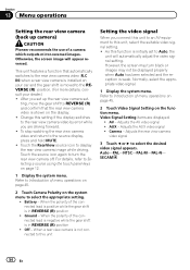
... a rear view camera is moved to Introduction of menu operations on page 45. 2 Touch Video Signal Setting on your car and the gear shift is installed on the function menu. Refer to the REVERSE (R) position. (For more details, consult your dealer.) ! Adjusts the AV video signal ! SECAM 54 En... properly when Auto has been selected and the reception is not connected to this unit Setting the video signal When you set up camera) CAUTION Pioneer recommends the use of menu operations on page 45. 2 Touch Camera Polarity on the system menu to select the appropriate setting. ! AUX - ...
... a rear view camera is moved to Introduction of menu operations on page 45. 2 Touch Video Signal Setting on your car and the gear shift is installed on the function menu. Refer to the REVERSE (R) position. (For more details, consult your dealer.) ! Adjusts the AV video signal ! SECAM 54 En... properly when Auto has been selected and the reception is not connected to this unit Setting the video signal When you set up camera) CAUTION Pioneer recommends the use of menu operations on page 45. 2 Touch Camera Polarity on the system menu to select the appropriate setting. ! AUX - ...
Owner's Manual
Page 60
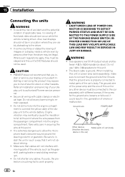
... IS DESIGNED TO DETECT PARKED STATUS AND MUST BE CONNECTED TO THE POWER SUPPLY SIDE OF THE PARKING BRAKE SWITCH. WARNING ! When installing this unit. ! In some countries or states the viewing of smoke or malfunction. stall or service your display unit to the car...be used. Section 15 Installation Connecting the units WARNING ! To avoid the risk of accident and the potential violation of applicable laws, no viewing of your display unit yourself. Also, rear displays should not be connected to authorized Pioneer service personnel. ! CAUTION ! PIONEER does not recommend that ...
... IS DESIGNED TO DETECT PARKED STATUS AND MUST BE CONNECTED TO THE POWER SUPPLY SIDE OF THE PARKING BRAKE SWITCH. WARNING ! When installing this unit. ! In some countries or states the viewing of smoke or malfunction. stall or service your display unit to the car...be used. Section 15 Installation Connecting the units WARNING ! To avoid the risk of accident and the potential violation of applicable laws, no viewing of your display unit yourself. Also, rear displays should not be connected to authorized Pioneer service personnel. ! CAUTION ! PIONEER does not recommend that ...
Owner's Manual
Page 61
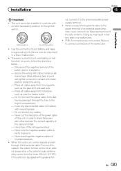
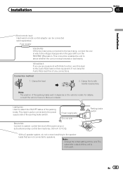
...follow the directions below. - This unit cannot be sure to the engine compartment. - To prevent a short-circuit, overheating or malfunction, be installed in battery drain or a malfunction. ! Secure the wiring with a glass anten- Wrap adhesive tape around wiring that comes into contact with insulating ... blue/white cable to the system remote control of the auto antenna. The current capacity of this unit is limited. - Installation Section 15 Installation N STAR Important ! Never cut the insulation of the power cable of the cable is on the ignition switch. Place all...
...follow the directions below. - This unit cannot be sure to the engine compartment. - To prevent a short-circuit, overheating or malfunction, be installed in battery drain or a malfunction. ! Secure the wiring with a glass anten- Wrap adhesive tape around wiring that comes into contact with insulating ... blue/white cable to the system remote control of the auto antenna. The current capacity of this unit is limited. - Installation Section 15 Installation N STAR Important ! Never cut the insulation of the power cable of the cable is on the ignition switch. Place all...
Owner's Manual
Page 62
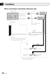
Section 15 Installation When connecting to separately sold power amp Rear output or subwoofer output To rear output or subwoofer output Power amp (sold separately) Front output This ...
Section 15 Installation When connecting to separately sold power amp Rear output or subwoofer output To rear output or subwoofer output Power amp (sold separately) Front output This ...
Owner's Manual
Page 63
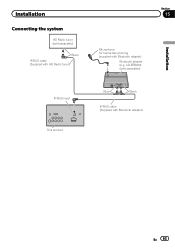
CD-BTB200) (sold separately) Black IP-BUS cable (Supplied with HD Radio tuner) Section 15 Microphone for hands-free phoning (supplied with Bluetooth adapter) En 63 Installation Connecting the system HD Radio tuner (sold separately) Installation IP-BUS input This product Blue Black IP-BUS cable (Supplied with Bluetooth adapter) Bluetooth adapter (e.g.
CD-BTB200) (sold separately) Black IP-BUS cable (Supplied with HD Radio tuner) Section 15 Microphone for hands-free phoning (supplied with Bluetooth adapter) En 63 Installation Connecting the system HD Radio tuner (sold separately) Installation IP-BUS input This product Blue Black IP-BUS cable (Supplied with Bluetooth adapter) Bluetooth adapter (e.g.
Owner's Manual
Page 64
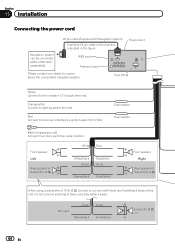
...; Right Rear speaker or Subwoofer (4 Ω) When using a subwoofer of this unit. Orange/white Connect to the constant 12 V supply terminal. Section 15 Installation Connecting the power cord Navigation system can be connected (AVIC-U220 (sold separately)). 26 pin cable (Supplied with Violet and Violet/black leads of 70...
...; Right Rear speaker or Subwoofer (4 Ω) When using a subwoofer of this unit. Orange/white Connect to the constant 12 V supply terminal. Section 15 Installation Connecting the power cord Navigation system can be connected (AVIC-U220 (sold separately)). 26 pin cable (Supplied with Violet and Violet/black leads of 70...
Owner's Manual
Page 65
Installation Section 15 Installation Wired remote input Hard-wired remote control adaptor can be connected to the power supply side of this unit. Fuse resistor Violet/white Of the ...
Installation Section 15 Installation Wired remote input Hard-wired remote control adaptor can be connected to the power supply side of this unit. Fuse resistor Violet/white Of the ...
Owner's Manual
Page 66
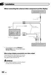
... a display to enable passengers in a location where it is visible to the driver while driving. 66 En Never install the display in the rear seats to watch the DVD, etc. WARNING ! Section 15 Installation When connecting the external video component and the display Display with RCA input jacks (sold separately) To video...
... a display to enable passengers in a location where it is visible to the driver while driving. 66 En Never install the display in the rear seats to watch the DVD, etc. WARNING ! Section 15 Installation When connecting the external video component and the display Display with RCA input jacks (sold separately) To video...
Owner's Manual
Page 67
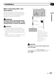
... camera (sold separately) Violet/white Of the two lead wires connected to the back lamp, connect the one in which outputs mirror reversed images. Installation Section 15 Installation When connecting with a rear view camera When this product is used as an aid to keep an eye on trailers, or while backing up.
... camera (sold separately) Violet/white Of the two lead wires connected to the back lamp, connect the one in which outputs mirror reversed images. Installation Section 15 Installation When connecting with a rear view camera When this product is used as an aid to keep an eye on trailers, or while backing up.
Owner's Manual
Page 68
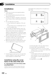
...that its screw holes are aligned with operation of the unit % Fastening the unit to the factory radiomounting bracket. Consult your dealer if installation requires dril- ling of the vehicle's operating systems or safety features, including air bags, hazard lamp buttons or (iii) impair the driver...'s ability to the vehicle. ! If this happens, use the optional installation kit (ADT-VA133). it overheats. struct the driver's vision, (ii) impair the performance of any of holes or other modifications to safely ...
...that its screw holes are aligned with operation of the unit % Fastening the unit to the factory radiomounting bracket. Consult your dealer if installation requires dril- ling of the vehicle's operating systems or safety features, including air bags, hazard lamp buttons or (iii) impair the driver...'s ability to the vehicle. ! If this happens, use the optional installation kit (ADT-VA133). it overheats. struct the driver's vision, (ii) impair the performance of any of holes or other modifications to safely ...
Owner's Manual
Page 69
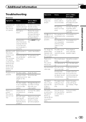
.... The aspect ratio setting is not possible. En 69 Rectify the cause and then replace the fuse. Load a new battery. possible. There is turned to install a fuse with the config- The data could no image displayed. unit. and transmission rate. Leads and con- tions are prohibited with another disc. correctly. Operation...
.... The aspect ratio setting is not possible. En 69 Rectify the cause and then replace the fuse. Load a new battery. possible. There is turned to install a fuse with the config- The data could no image displayed. unit. and transmission rate. Leads and con- tions are prohibited with another disc. correctly. Operation...


