Owner's Manual
Page 10
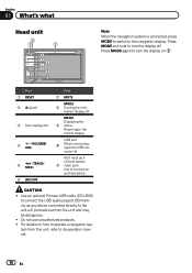
...(3.5 mm stereo/ b video jack) Use to the normal display. mation display off . CAUTION ! Returning to connect an auxiliary device. Use an optional Pioneer USB cable (CD-U50E) to connect the USB audio player/USB memory as any device connected directly to the unit will protrude out from this ...+/- (VOLUME/ VOL) 5 c/d (TRACK/ SEEK) 6 SRC/OFF Part 7 MUTE MODE 8 Turning the infor- Section 03 What's what Head unit 2 1 3 4 5 7 6 89 ba Note When the navigation system is connected, press MODE to switch to operate a navigation sys- Press MODE and hold to turn the display on how to the...
...(3.5 mm stereo/ b video jack) Use to the normal display. mation display off . CAUTION ! Returning to connect an auxiliary device. Use an optional Pioneer USB cable (CD-U50E) to connect the USB audio player/USB memory as any device connected directly to the unit will protrude out from this ...+/- (VOLUME/ VOL) 5 c/d (TRACK/ SEEK) 6 SRC/OFF Part 7 MUTE MODE 8 Turning the infor- Section 03 What's what Head unit 2 1 3 4 5 7 6 89 ba Note When the navigation system is connected, press MODE to switch to operate a navigation sys- Press MODE and hold to turn the display on how to the...
Owner's Manual
Page 57
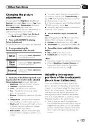
... Off. (Refer to display Picture Adjustment. Color - play ! Adjusts the color tempera- Adjusts phase shifting by dot clock when a Navigation system is connected # You cannot adjust the picture adjustment for the Navigation system. NAVI Rear View Adjusting the Picture Adjustment for the rear view camera when Camera Polarity is emphasized) ! There are...
... Off. (Refer to display Picture Adjustment. Color - play ! Adjusts the color tempera- Adjusts phase shifting by dot clock when a Navigation system is connected # You cannot adjust the picture adjustment for the Navigation system. NAVI Rear View Adjusting the Picture Adjustment for the rear view camera when Camera Polarity is emphasized) ! There are...
Owner's Manual
Page 64
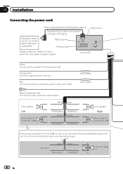
... terminal controlled by ignition switch (12 V DC). This product RGB input Antenna input Please contact your dealer to inquire about the connectable navigation system. Section 15 Installation Connecting the power cord Navigation system can be sure to connect with Navigation system) Insert the 26 pin cable in the direction indicated in the figure.
... terminal controlled by ignition switch (12 V DC). This product RGB input Antenna input Please contact your dealer to inquire about the connectable navigation system. Section 15 Installation Connecting the power cord Navigation system can be sure to connect with Navigation system) Insert the 26 pin cable in the direction indicated in the figure.


