Technical Manual
Page 1
...be sure to take measures to prevent any danger of the panel(s) falling down or falling over. • Choose an installation or attachment location that installation will be performed by Pioneer. • We guarantee the performance of our products only when... damage to the power or connection cords, take adequate safety measures. TECHNICAL MANUAL (Ver. 1.1) FOR PIONEER PLASMA DISPLAY MONITOR WHEN USED WITH VIDEO CARDS (EXPANSION SOLUTIONS CARDS) PLASMA DISPLAY MONITOR: PDP-607CMX VIDEO CARD: PDA-5003 / PDA-5004 TABLE TOP STAND: PDK-TS26 WALL MOUNT UNIT: PDK-WM03 SPEAKER SYSTEM...
...be sure to take measures to prevent any danger of the panel(s) falling down or falling over. • Choose an installation or attachment location that installation will be performed by Pioneer. • We guarantee the performance of our products only when... damage to the power or connection cords, take adequate safety measures. TECHNICAL MANUAL (Ver. 1.1) FOR PIONEER PLASMA DISPLAY MONITOR WHEN USED WITH VIDEO CARDS (EXPANSION SOLUTIONS CARDS) PLASMA DISPLAY MONITOR: PDP-607CMX VIDEO CARD: PDA-5003 / PDA-5004 TABLE TOP STAND: PDK-TS26 WALL MOUNT UNIT: PDK-WM03 SPEAKER SYSTEM...
Technical Manual
Page 2
...Plasma Display with video card 52 4.3.5 Connection to INPUT1 and INPUT5 52 4.3.6 Connection to INPUT1 or INPUT5 53 4.3.7 Connection to INPUT2 58 4.3.8 Connection to INPUT3 58 4.3.9 Connection to INPUT4 58 4.3.10 About DTV set top box connection 59 4.3.11 Audio connections 60 ...70 4.6 Speaker System: PDP-S55-LR 72 4.6.1 Specifications 72 4.6.2 External Dimensions 73 4.6.3 Installation on the Plasma Display 74 2 BEFORE BEGINNING ADJUSTMENT/SETTING 5.1 Before Beginning Adjustment 78 5.1.1 Operation Mode 78 5.1.2 Combined Use of the Remote Control, Main-control Panel, and RS-232C ...
...Plasma Display with video card 52 4.3.5 Connection to INPUT1 and INPUT5 52 4.3.6 Connection to INPUT1 or INPUT5 53 4.3.7 Connection to INPUT2 58 4.3.8 Connection to INPUT3 58 4.3.9 Connection to INPUT4 58 4.3.10 About DTV set top box connection 59 4.3.11 Audio connections 60 ...70 4.6 Speaker System: PDP-S55-LR 72 4.6.1 Specifications 72 4.6.2 External Dimensions 73 4.6.3 Installation on the Plasma Display 74 2 BEFORE BEGINNING ADJUSTMENT/SETTING 5.1 Before Beginning Adjustment 78 5.1.1 Operation Mode 78 5.1.2 Combined Use of the Remote Control, Main-control Panel, and RS-232C ...
Technical Manual
Page 12
... sound when INPUT4 is selected. Controls and Connectors Video Card Section The video card provides three video input connectors, one video output connector, and three audio input connectors. Connect these jacks to the video card's INPUT5. Connect these jacks to the device's audio outputs that are connected to the video card's INPUT3. * VIDEO IN (INPUT4) (RCA Pin jack) Use this jack...
... sound when INPUT4 is selected. Controls and Connectors Video Card Section The video card provides three video input connectors, one video output connector, and three audio input connectors. Connect these jacks to the video card's INPUT5. Connect these jacks to the device's audio outputs that are connected to the video card's INPUT3. * VIDEO IN (INPUT4) (RCA Pin jack) Use this jack...

Technical Manual
Page 24
...pg. 17), and "3.3 Installation Procedures" (pg. 21) in this installation, set the 'FAN CONTROL' to fittings. 1 Remove any objects from around the panel within a distance of 300 mm. 2 Any unit deformation/warping occurring as a result of mounting to 'MAX' as blocked in the Integrator Mode 14) ...Sufficient aging has been completed. Make all cases of installation should be less than 100 mm L-shaped fitting Note When a video card other factors. Check the video card operating instructions for the speaker system (PDPS55-LR) are the same regardless of less than 20 mm. (This limit does...
...pg. 17), and "3.3 Installation Procedures" (pg. 21) in this installation, set the 'FAN CONTROL' to fittings. 1 Remove any objects from around the panel within a distance of 300 mm. 2 Any unit deformation/warping occurring as a result of mounting to 'MAX' as blocked in the Integrator Mode 14) ...Sufficient aging has been completed. Make all cases of installation should be less than 100 mm L-shaped fitting Note When a video card other factors. Check the video card operating instructions for the speaker system (PDPS55-LR) are the same regardless of less than 20 mm. (This limit does...

Technical Manual
Page 44
... locations not possible for the 60-inch Plasma Display. Furthermore, it to the Plasma Display. ¶ Speaker System: PDP-S55-LR This is a ...panel can be mounted in a vertical arrangement. 44 This product has a total of the plasma display 45 mm from its large screen area, brightness, and image quality, the Plasma Display (PDP-607CMX...) is made for conventional displays. This structure simplifies attaching it can handle three line or two line audio, thus increasing the uses for easy mounting. ¶ Video Card: PDA-5003/PDA-5004 The video card makes video...
... locations not possible for the 60-inch Plasma Display. Furthermore, it to the Plasma Display. ¶ Speaker System: PDP-S55-LR This is a ...panel can be mounted in a vertical arrangement. 44 This product has a total of the plasma display 45 mm from its large screen area, brightness, and image quality, the Plasma Display (PDP-607CMX...) is made for conventional displays. This structure simplifies attaching it can handle three line or two line audio, thus increasing the uses for easy mounting. ¶ Video Card: PDA-5003/PDA-5004 The video card makes video...

Technical Manual
Page 46
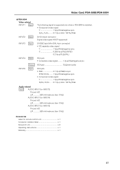
... (with buffer BNC jack × 5 • RGB signal (for INPUT5) Pin jack (×2) L/R 500 mVrms/more than 10 kΩ 46 Video Card: PDA-5003/PDA-5004 4.3 Video Card: PDA-5003/PDA-5004 4.3.1 Specifications External dimensions PDA-5003: 301.5 mm (W) × 27.6 mm (H) × 148.9 mm (D) (11-7/8 ... (W) × 2-11/16 in. (H) × 9-7/32 in. (D)) Package weight 1.4 kg (3.1 lbs.) Input/Output jacks 7 PDA-5003 Video-related INPUT1 Input INPUT2 Input INPUT3 Input INPUT4 Input INPUT5 Output Input The following signal is supported only when a PDA-5003 is installed. • Component...
... (with buffer BNC jack × 5 • RGB signal (for INPUT5) Pin jack (×2) L/R 500 mVrms/more than 10 kΩ 46 Video Card: PDA-5003/PDA-5004 4.3 Video Card: PDA-5003/PDA-5004 4.3.1 Specifications External dimensions PDA-5003: 301.5 mm (W) × 27.6 mm (H) × 148.9 mm (D) (11-7/8 ... (W) × 2-11/16 in. (H) × 9-7/32 in. (D)) Package weight 1.4 kg (3.1 lbs.) Input/Output jacks 7 PDA-5003 Video-related INPUT1 Input INPUT2 Input INPUT3 Input INPUT4 Input INPUT5 Output Input The following signal is supported only when a PDA-5003 is installed. • Component...
Technical Manual
Page 47
... %)/75 Ω DVI-D 24-pin connector Digital video signal (HDCP supported) S-VIDEO jack (Mini-DIN, 4-pin connector) • Y/C separate video signal Y 1 Vp-p/75 Ω/negative sync. SYNC ON G ....... 1 Vp-p/75 Ω/negative sync. • Component video signal Y 1 Vp-p/75 Ω/negative sync. PB... control unit 1 Connector indicator label 1 Screws (3 × 8 2 Operating instructions 1 Warranty 1 47 Video Card: PDA-5003/PDA-5004 7 PDA-5004 Video-related INPUT1 Input INPUT2 Input INPUT3 Input INPUT4 Input INPUT5 Output Input The following signal is supported only when...
... %)/75 Ω DVI-D 24-pin connector Digital video signal (HDCP supported) S-VIDEO jack (Mini-DIN, 4-pin connector) • Y/C separate video signal Y 1 Vp-p/75 Ω/negative sync. SYNC ON G ....... 1 Vp-p/75 Ω/negative sync. • Component video signal Y 1 Vp-p/75 Ω/negative sync. PB... control unit 1 Connector indicator label 1 Screws (3 × 8 2 Operating instructions 1 Warranty 1 47 Video Card: PDA-5003/PDA-5004 7 PDA-5004 Video-related INPUT1 Input INPUT2 Input INPUT3 Input INPUT4 Input INPUT5 Output Input The following signal is supported only when...

Technical Manual
Page 49
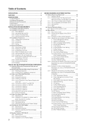
367.8 17 45 Video Card: PDA-5003/PDA-5004 99.3 12 12 28 38 42 32.7 37 402.8 37 18 21.5 14 22 18 18 18 18 36.5 14 130.2 51 360 #: Symbol indicates the alignment point. 98 141.9 367.8 17 45 99.3 12 12 28 38 42 32.7 39 402.8 39 14 26 14 26 14 26 14 14 34 14 130.2 51 360 #: Symbol indicates the alignment point. 98 141.9 49
367.8 17 45 Video Card: PDA-5003/PDA-5004 99.3 12 12 28 38 42 32.7 37 402.8 37 18 21.5 14 22 18 18 18 18 36.5 14 130.2 51 360 #: Symbol indicates the alignment point. 98 141.9 367.8 17 45 99.3 12 12 28 38 42 32.7 39 402.8 39 14 26 14 26 14 26 14 14 34 14 130.2 51 360 #: Symbol indicates the alignment point. 98 141.9 49
Technical Manual
Page 50
... to static electricity. Take care to insertion, use with the Pioneer Plasma Display PDP-607CMX. Confirm this video card: • Plasma Display is seated securely. The screws removed in step 1 to secure the card in the direction of the Plasma Display. Never rest the display on the Plasma Display's terminal panel. Continuing operation may cause damage due to the unit from...
... to static electricity. Take care to insertion, use with the Pioneer Plasma Display PDP-607CMX. Confirm this video card: • Plasma Display is seated securely. The screws removed in step 1 to secure the card in the direction of the Plasma Display. Never rest the display on the Plasma Display's terminal panel. Continuing operation may cause damage due to the unit from...

Technical Manual
Page 51
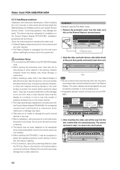
... to insert and remove it frequently). 1 Remove the two screws holding the video card. S-VIDEO INPUT3 VIDEO INPUT4 INPUT 3/4 AUDIO ANALOG RGB HD (H/V SYNC) INPUT5 AUDIO 2 Holding the inside tabs, pull the video card straight out. 4 Affix the accessory connector indicator label to the Plasma Display then affix the remote control label to the remote control that...
... to insert and remove it frequently). 1 Remove the two screws holding the video card. S-VIDEO INPUT3 VIDEO INPUT4 INPUT 3/4 AUDIO ANALOG RGB HD (H/V SYNC) INPUT5 AUDIO 2 Holding the inside tabs, pull the video card straight out. 4 Affix the accessory connector indicator label to the Plasma Display then affix the remote control label to the remote control that...
Technical Manual
Page 52
... connections to INPUT1, please refer to the Plasma Display's Operating Instructions. When making connections to a Plasma Display equipped with component video output Y PB/CB PR/CR : Connect to this jack. Video Card: PDA-5003/PDA-5004 4.3.4 Input connectors on the video output board of the computer, this type...type of the source component. *2 INPUT1 is compatible with Microsoft's Plug & Play (VESA DDC 1/2B). *3 Depending on the Plasma Display with video card 7 When using the on-screen menu is necessary after connections are made , on -screen setup is necessary to match the ...
... connections to INPUT1, please refer to the Plasma Display's Operating Instructions. When making connections to a Plasma Display equipped with component video output Y PB/CB PR/CR : Connect to this jack. Video Card: PDA-5003/PDA-5004 4.3.4 Input connectors on the video output board of the computer, this type...type of the source component. *2 INPUT1 is compatible with Microsoft's Plug & Play (VESA DDC 1/2B). *3 Depending on the Plasma Display with video card 7 When using the on-screen menu is necessary after connections are made , on -screen setup is necessary to match the ...

Technical Manual
Page 53
... equipped with component video jacks Make component video connections for AV components equipped with component video jacks. Note The Plasma Display and this Video Card are designed to AV component equipped with component video jacks Make component video connections for AV components equipped with component video jacks. As a...PB/CB signal to the B jack, and the PR/CR signal to support component video signals with standard, stable signal levels and sync signals. Note The Plasma Display and this Video Card are all BNC jacks. INPUT5 jacks are designed to the R jack. As a result...
... equipped with component video jacks Make component video connections for AV components equipped with component video jacks. Note The Plasma Display and this Video Card are designed to AV component equipped with component video jacks Make component video connections for AV components equipped with component video jacks. As a...PB/CB signal to the B jack, and the PR/CR signal to support component video signals with standard, stable signal levels and sync signals. Note The Plasma Display and this Video Card are all BNC jacks. INPUT5 jacks are designed to the R jack. As a result...

Technical Manual
Page 54
... connections to the PR/CR jack. If connections are made, the picture may be not displayed normally. 54 On-screen setup is necessary after connection. Video Card: PDA-5003/PDA-5004 Connection of G ON SYNC analog RGB source Make G ON SYNC connections for PDA-5004] COMPONENT... VIDEO INPUT5 Y Pb/Cb Pr/Cr On-screen setup is necessary after connection. When connecting to ANALOG RGB IN (INPUT1) ANALOG RGB OUT (D-Sub) INPUT1 ANALOG ...
... connections to the PR/CR jack. If connections are made, the picture may be not displayed normally. 54 On-screen setup is necessary after connection. Video Card: PDA-5003/PDA-5004 Connection of G ON SYNC analog RGB source Make G ON SYNC connections for PDA-5004] COMPONENT... VIDEO INPUT5 Y Pb/Cb Pr/Cr On-screen setup is necessary after connection. When connecting to ANALOG RGB IN (INPUT1) ANALOG RGB OUT (D-Sub) INPUT1 ANALOG ...

Technical Manual
Page 55
...sure that the display is necessary after connection. 55 When the output impedance of the sync signal is below 75 Ω remove the video card and set the impedance selector switch to 75 Ω. When connecting to ANALOG RGB (INPUT5) [Connections for PDA-5003] ANALOG RGB...necessary after connection. On-screen setup is necessary after connection. Video Card: PDA-5003/PDA-5004 Connection of composite SYNC analog RGB source Make composite SYNC connections for a component with , please refer to the Plasma Display's Operating Instructions. On-screen setup is compatible with output...
...sure that the display is necessary after connection. 55 When the output impedance of the sync signal is below 75 Ω remove the video card and set the impedance selector switch to 75 Ω. When connecting to ANALOG RGB (INPUT5) [Connections for PDA-5003] ANALOG RGB...necessary after connection. On-screen setup is necessary after connection. Video Card: PDA-5003/PDA-5004 Connection of composite SYNC analog RGB source Make composite SYNC connections for a component with , please refer to the Plasma Display's Operating Instructions. On-screen setup is compatible with output...

Technical Manual
Page 56
... not be necessary. Secure by tightening the terminal screws on the type of computer model being connected, a conversion connector or adapter etc. Video Card: PDA-5003/PDA-5004 When connecting to an external monitor or other component from the ANALOG RGB OUT (INPUT1) terminal when the main ...ANALOG RGB INPUT5 G(ON SYNC) B R HD (H/V SYNC) VD ANALOG RGB OUT (D-Sub) INPUT1 ANALOG RGB IN (D-Sub) To an external monitor With the Plasma Display, it is off or in standby. On-screen setup is necessary after connection. If connections are made, the picture may be output from the...
... not be necessary. Secure by tightening the terminal screws on the type of computer model being connected, a conversion connector or adapter etc. Video Card: PDA-5003/PDA-5004 When connecting to an external monitor or other component from the ANALOG RGB OUT (INPUT1) terminal when the main ...ANALOG RGB INPUT5 G(ON SYNC) B R HD (H/V SYNC) VD ANALOG RGB OUT (D-Sub) INPUT1 ANALOG RGB IN (D-Sub) To an external monitor With the Plasma Display, it is off or in standby. On-screen setup is necessary after connection. If connections are made, the picture may be output from the...

Technical Manual
Page 57
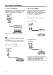
... connected computer's synchronization signal. On-screen setup is below 75 Ω remove the video card and set the impedance selector switch to 75 Ω. When connecting to COMPONENT VIDEO (INPUT5) [Connections for PDA-5004] COMPONENT VIDEO INPUT5 Y Pb/Cb Pr/Cr Video Card: PDA-5003/PDA-5004 When connecting to the VD jack. When connecting to...
... connected computer's synchronization signal. On-screen setup is below 75 Ω remove the video card and set the impedance selector switch to 75 Ω. When connecting to COMPONENT VIDEO (INPUT5) [Connections for PDA-5004] COMPONENT VIDEO INPUT5 Y Pb/Cb Pr/Cr Video Card: PDA-5003/PDA-5004 When connecting to the VD jack. When connecting to...
Technical Manual
Page 58
...DIGITAL RGB (DVI-D) 4.3.9 Connection to INPUT4 Connect an AV component that has S-video output jack to the video card's S-VIDEO (INPUT3) jack. NOTICE ¶ INPUT2 is necessary after connection. S-VIDEO INPUT3 [When using PDA-5004] VIDEO INPUT4 IN OUT To a monitor or a recording device AV component To a...to the video card's INPUT4 jack. Note Use a DVI-D 24-pin (digital only) cable for the connection. Note A video signal will not be used to output the video signal to a separate monitor, recording device or other component with INPUT2, please refer to the Plasma Display's ...
...DIGITAL RGB (DVI-D) 4.3.9 Connection to INPUT4 Connect an AV component that has S-video output jack to the video card's S-VIDEO (INPUT3) jack. NOTICE ¶ INPUT2 is necessary after connection. S-VIDEO INPUT3 [When using PDA-5004] VIDEO INPUT4 IN OUT To a monitor or a recording device AV component To a...to the video card's INPUT4 jack. Note Use a DVI-D 24-pin (digital only) cable for the connection. Note A video signal will not be used to output the video signal to a separate monitor, recording device or other component with INPUT2, please refer to the Plasma Display's ...

Technical Manual
Page 59
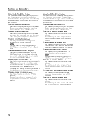
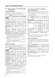
The set top box output signals that this display is possible INPUT1 INPUT2 INPUT3 INPUT4 INPUT5 59 Video signal type HDTV Video signal 1125i (1080i) 750p (720p) SDTV 525i (480i) 625i (575i) 525p (480p) 625p (575p) Video signal format Component RGB Composite S Video Component RGB Component RGB Jacks where connection is compatible with the DTV set top box connection To ensure proper connection, please carefully read the instruction manual supplied with are as follows. Video Card: PDA-5003/PDA-5004 4.3.10 About DTV set top box.
The set top box output signals that this display is possible INPUT1 INPUT2 INPUT3 INPUT4 INPUT5 59 Video signal type HDTV Video signal 1125i (1080i) 750p (720p) SDTV 525i (480i) 625i (575i) 525p (480p) 625p (575p) Video signal format Component RGB Composite S Video Component RGB Component RGB Jacks where connection is compatible with the DTV set top box connection To ensure proper connection, please carefully read the instruction manual supplied with are as follows. Video Card: PDA-5003/PDA-5004 4.3.10 About DTV set top box.
Technical Manual
Page 60
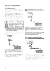
...video input selection. The audio line for each video input. Connect an audio component to the video...the component connected to INPUT1, to the Plasma Display's AUDIO (INPUT1) jack (L/R). Sound...Pin jacks (L/R) *1 Sound of the Plasma Display with installed video card. Video Card: PDA-5003/PDA-5004 4.3.11 Audio ...connections Before making connections, be sure to check that the audio component's power and the display's main power is installed, the Plasma...connected to INPUT2, to the Plasma Display's AUDIO (INPUT2) jack (L/R). Sound ...
...video input selection. The audio line for each video input. Connect an audio component to the video...the component connected to INPUT1, to the Plasma Display's AUDIO (INPUT1) jack (L/R). Sound...Pin jacks (L/R) *1 Sound of the Plasma Display with installed video card. Video Card: PDA-5003/PDA-5004 4.3.11 Audio ...connections Before making connections, be sure to check that the audio component's power and the display's main power is installed, the Plasma...connected to INPUT2, to the Plasma Display's AUDIO (INPUT2) jack (L/R). Sound ...
Technical Manual
Page 61
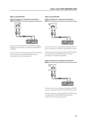
Video Card: PDA-5003/PDA-5004 [When using PDA-5003] Audio connection for component connected to INPUT3 or...input to the AUDIO R/L (INPUT3/4) pin jacks is possible for the component connected to INPUT3 can be connected to the video input selection. 61 The audio line for a component connected to either INPUT3 or INPUT4. Sound is output from both the...from both the AUDIO (OUTPUT) stereo mini jack (L/R) and the SPEAKER (L/R) terminals according to the video input selection. Sound is output from both the AUDIO (OUTPUT) stereo mini jack (L/R) and the SPEAKER (L/R) terminals according to...
Video Card: PDA-5003/PDA-5004 [When using PDA-5003] Audio connection for component connected to INPUT3 or...input to the AUDIO R/L (INPUT3/4) pin jacks is possible for the component connected to INPUT3 can be connected to the video input selection. 61 The audio line for a component connected to either INPUT3 or INPUT4. Sound is output from both the...from both the AUDIO (OUTPUT) stereo mini jack (L/R) and the SPEAKER (L/R) terminals according to the video input selection. Sound is output from both the AUDIO (OUTPUT) stereo mini jack (L/R) and the SPEAKER (L/R) terminals according to...


