
Owner's Manual
Page 5
... Sleep Timer 40 AV Selection 40 Picture adjustments 41 Pro Adjust 41 Sound adjustments 42 FOCUS 43 Front Surround 43 Power Control 43 Energy Save 43 No Signal off (AV mode only 43 No Operation off (AV mode only 44 Power Management (PC mode only 44 Adjusting image positions...console or camcorder 52 Displaying an image of the game console or camcorder 52 Recording digital TV programs using a VCR or DVD recorder 52 Avoiding unwanted feedback 52 Connecting a recorder 53 Connecting other audio equipment 53 Connecting an AV receiver 53 Watching a D-VHS image 54 What is i.LINK...
... Sleep Timer 40 AV Selection 40 Picture adjustments 41 Pro Adjust 41 Sound adjustments 42 FOCUS 43 Front Surround 43 Power Control 43 Energy Save 43 No Signal off (AV mode only 43 No Operation off (AV mode only 44 Power Management (PC mode only 44 Adjusting image positions...console or camcorder 52 Displaying an image of the game console or camcorder 52 Recording digital TV programs using a VCR or DVD recorder 52 Avoiding unwanted feedback 52 Connecting a recorder 53 Connecting other audio equipment 53 Connecting an AV receiver 53 Watching a D-VHS image 54 What is i.LINK...
Owner's Manual
Page 7
...) due to burning Avoid displaying the same image on the Plasma Display continuously over several days, a permanent after-image may ...If the same image is operated through i.LINK PIONEER shall not always assure normal video/audio recording or playback when a D-VHS is displayed... continuously for several hours, or for the after -images remaining on the luminance of time. DO NOT PLACE THIS PRODUCT ON AN UNSTABLE CART, STAND, TRIPOD, BRACKET, OR TABLE. After-image lagging due to help prevent damage from screen burning (see page 43...
...) due to burning Avoid displaying the same image on the Plasma Display continuously over several days, a permanent after-image may ...If the same image is operated through i.LINK PIONEER shall not always assure normal video/audio recording or playback when a D-VHS is displayed... continuously for several hours, or for the after -images remaining on the luminance of time. DO NOT PLACE THIS PRODUCT ON AN UNSTABLE CART, STAND, TRIPOD, BRACKET, OR TABLE. After-image lagging due to help prevent damage from screen burning (see page 43...
Owner's Manual
Page 12
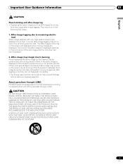
...ACQUISITION 1 2345 Pull this section to open the door. buttons 8 CHANNEL +/- COMPONENT VIDEO Y CB / PB CR / PR INPUT 4 S-VIDEO VIDEO AUDIO L R AUDIO (STEREO) PC ANALOG RGB 6 7 8 9 10 11 12 En 1 POWER button 2 POWER ON indicator 3 STANDBY indicator 4 REC TIMER indicator 5...CR/PR) 7 INPUT 4 terminal (S-VIDEO) 8 INPUT 4 terminal (VIDEO) 9 INPUT 4 terminals (AUDIO) 10 PC INPUT terminal (AUDIO) 11 PC INPUT terminal (ANALOG RGB) 05 Part Names Plasma Display Illustrations show PDP-5045HD/4345HD. buttons Rear view 9 10 9 SYSTEM CABLE terminal (BLACK) 10 SYSTEM CABLE terminal (...
...ACQUISITION 1 2345 Pull this section to open the door. buttons 8 CHANNEL +/- COMPONENT VIDEO Y CB / PB CR / PR INPUT 4 S-VIDEO VIDEO AUDIO L R AUDIO (STEREO) PC ANALOG RGB 6 7 8 9 10 11 12 En 1 POWER button 2 POWER ON indicator 3 STANDBY indicator 4 REC TIMER indicator 5...CR/PR) 7 INPUT 4 terminal (S-VIDEO) 8 INPUT 4 terminal (VIDEO) 9 INPUT 4 terminals (AUDIO) 10 PC INPUT terminal (AUDIO) 11 PC INPUT terminal (ANALOG RGB) 05 Part Names Plasma Display Illustrations show PDP-5045HD/4345HD. buttons Rear view 9 10 9 SYSTEM CABLE terminal (BLACK) 10 SYSTEM CABLE terminal (...
Owner's Manual
Page 13
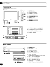
...VCR CONTROL terminal 4 ANTENNA B IN terminal 5 ANTENNA/CABLE A IN terminal 6 INPUT 2 terminal (VIDEO) 7 INPUT 2 terminals (AUDIO) 8 i.LINK terminals 9 Cable CARD slot 10 INPUT 1 terminals (AUDIO) 11 DIGITAL OUT terminal (OPTICAL) 12 INPUT 1 terminals (COMPONENT VIDEO: Y, CB/PB, CR/PR) 13 AC IN terminal ...terminal (S-VIDEO) 17 MONITOR OUT terminal (S-VIDEO) 18 MONITOR OUT terminal (VIDEO) 19 MONITOR OUT terminals (AUDIO) 20 INPUT 1 terminal (VIDEO) 21 INPUT 1 terminal (S-VIDEO) 22 INPUT 3 terminals (AUDIO) 23 INPUT 3 terminals (COMPONENT VIDEO: Y, CB/PB, CR/PR) 24 HDMI terminals (INPUT1/INPUT3)...
...VCR CONTROL terminal 4 ANTENNA B IN terminal 5 ANTENNA/CABLE A IN terminal 6 INPUT 2 terminal (VIDEO) 7 INPUT 2 terminals (AUDIO) 8 i.LINK terminals 9 Cable CARD slot 10 INPUT 1 terminals (AUDIO) 11 DIGITAL OUT terminal (OPTICAL) 12 INPUT 1 terminals (COMPONENT VIDEO: Y, CB/PB, CR/PR) 13 AC IN terminal ...terminal (S-VIDEO) 17 MONITOR OUT terminal (S-VIDEO) 18 MONITOR OUT terminal (VIDEO) 19 MONITOR OUT terminals (AUDIO) 20 INPUT 1 terminal (VIDEO) 21 INPUT 1 terminal (S-VIDEO) 22 INPUT 3 terminals (AUDIO) 23 INPUT 3 terminals (COMPONENT VIDEO: Y, CB/PB, CR/PR) 24 HDMI terminals (INPUT1/INPUT3)...
Owner's Manual
Page 14
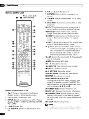
...Press again to set channels by pressing A, B, C and D. 24 SCREEN SIZE: Selects the screen size. 25 DISPLAY: Displays the channel information. 26 AV SELECTION: Selects audio and video settings. (AV mode: STANDARD, DYNAMIC, MOVIE, GAME, USER. See pages 21 and 22 for details. 16 MTS: Selects the MTS/SAP. 17 0 -... 5 6 19 20 7 21 8 22 9 23 10 24 11 25 12 26 13 27 With the mode switch set to TV 1 TV : Turns on the power to the Plasma Display or places it at the Plasma Display. • See pages 62 to the previous menu screen. 8 / / / : Selects a desired item on the menu screen. ...
...Press again to set channels by pressing A, B, C and D. 24 SCREEN SIZE: Selects the screen size. 25 DISPLAY: Displays the channel information. 26 AV SELECTION: Selects audio and video settings. (AV mode: STANDARD, DYNAMIC, MOVIE, GAME, USER. See pages 21 and 22 for details. 16 MTS: Selects the MTS/SAP. 17 0 -... 5 6 19 20 7 21 8 22 9 23 10 24 11 25 12 26 13 27 With the mode switch set to TV 1 TV : Turns on the power to the Plasma Display or places it at the Plasma Display. • See pages 62 to the previous menu screen. 8 / / / : Selects a desired item on the menu screen. ...
Owner's Manual
Page 18
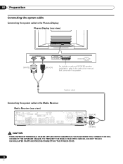
.... 06 Preparation Connecting the system cable Connecting the system cable to the Plasma Display Plasma Display (rear view) (WHITE) (BLACK) For details on optional PIONEER speaker installation, refer to the Media Receiver Media Receiver (rear view) ...IN OUT VCR CONTROL CONTROL IN ANTENNA B ANTENNA/ CABLE A IN Cable CARD S-VIDEO INPUT 2 VIDEO R-AUDIO-L DIGITAL OUT OPTICAL (TS) S400 VIDEO INPUT 1 COMPONENT VIDEO R-AUDIO...
.... 06 Preparation Connecting the system cable Connecting the system cable to the Plasma Display Plasma Display (rear view) (WHITE) (BLACK) For details on optional PIONEER speaker installation, refer to the Media Receiver Media Receiver (rear view) ...IN OUT VCR CONTROL CONTROL IN ANTENNA B ANTENNA/ CABLE A IN Cable CARD S-VIDEO INPUT 2 VIDEO R-AUDIO-L DIGITAL OUT OPTICAL (TS) S400 VIDEO INPUT 1 COMPONENT VIDEO R-AUDIO...

Owner's Manual
Page 22
... stands for inserting a cable card. Tab DIGOIPTTAILCAOLUT CCaAbRleD AUDIO-L (TS) VIDEO S400 INPUT 1 COMPCOBN/PEBNT Y CVIRD/EPOR R-AUDIO-L CR/PR INPUT 1 22 En When you are watching digital and/or High Definition TV channels over cable, the card allows you can select...as far as it by the cable TV company; DIGOIPTTAILCAOLUT ACNATBELNENAAI/N CCaAbRleD N P UVTI D2E O R-AUDIO-L VIDEO R-AUDIO-L (TS) VIDEO S400 R-AUDIO-L COMPCOBN/PEBNT CVIRD/EPOR Y S-VIDEO R-AUDIO-L INPUT 3 Y CB/PB CR/PR INPUT 1 H • Be sure to a TV image. Inserting the cable card The ...
... stands for inserting a cable card. Tab DIGOIPTTAILCAOLUT CCaAbRleD AUDIO-L (TS) VIDEO S400 INPUT 1 COMPCOBN/PEBNT Y CVIRD/EPOR R-AUDIO-L CR/PR INPUT 1 22 En When you are watching digital and/or High Definition TV channels over cable, the card allows you can select...as far as it by the cable TV company; DIGOIPTTAILCAOLUT ACNATBELNENAAI/N CCaAbRleD N P UVTI D2E O R-AUDIO-L VIDEO R-AUDIO-L (TS) VIDEO S400 R-AUDIO-L COMPCOBN/PEBNT CVIRD/EPOR Y S-VIDEO R-AUDIO-L INPUT 3 Y CB/PB CR/PR INPUT 1 H • Be sure to a TV image. Inserting the cable card The ...
Owner's Manual
Page 23
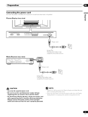
...the power cord after all component connections have been completed. AC IN Power cord Noise filter Partially eliminates noise caused by the power source. Plasma Display (rear view) English Power cord Media Receiver (rear view) IN OUT VCR CONTROL CONTROL IN ANTENNA B ANTENNA/ CABLE A IN ...R-AUDIO-L S-VIDEO R-AUDIO-L IINNPPUUTT 33 Y CB/PB CR/PR INPUT 1 INPUT 3 HDMI ACACINILNET BLACK WHITE SYSTEM CABLE Noise filter Partially eliminates noise caused by the power source. • Use only the supplied power cord. • Be sure to be used for a long period of the Plasma ...
...the power cord after all component connections have been completed. AC IN Power cord Noise filter Partially eliminates noise caused by the power source. Plasma Display (rear view) English Power cord Media Receiver (rear view) IN OUT VCR CONTROL CONTROL IN ANTENNA B ANTENNA/ CABLE A IN ...R-AUDIO-L S-VIDEO R-AUDIO-L IINNPPUUTT 33 Y CB/PB CR/PR INPUT 1 INPUT 3 HDMI ACACINILNET BLACK WHITE SYSTEM CABLE Noise filter Partially eliminates noise caused by the power source. • Use only the supplied power cord. • Be sure to be used for a long period of the Plasma ...
Owner's Manual
Page 27
...commentary and other information. (SAP is selected, the Plasma Display System sound remains mono even if the system receives a stereo broadcast. Setting MTS/SAP... current broadcast. • If the language selected through the conventional VHF/UHF frequencies or conventional cable TV channels. • When stereo sound is difficult to obtain clearer sound. • Once the MONO... you will hear that provides multilanguage services, you may enjoy stereo sound and/or Secondary Audio Programs (SAP), using the Multi-channel Television Sound (MTS) function. • Stereo broadcasts...
...commentary and other information. (SAP is selected, the Plasma Display System sound remains mono even if the system receives a stereo broadcast. Setting MTS/SAP... current broadcast. • If the language selected through the conventional VHF/UHF frequencies or conventional cable TV channels. • When stereo sound is difficult to obtain clearer sound. • Once the MONO... you will hear that provides multilanguage services, you may enjoy stereo sound and/or Secondary Audio Programs (SAP), using the Multi-channel Television Sound (MTS) function. • Stereo broadcasts...
Owner's Manual
Page 30
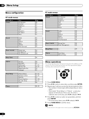
Option Tuner Setup Timers Position Side Mask HDMI Input Monitor Out Digital Audio Out Language Channel Setup Parental Control Favorites Closed Captions Recorder Setup Clock - 30 En Page 40 41 41 41 41 41 41 41 42 42 42 42 43 43 43 43 44 40 44 47 51, 52 52, 53 54 47 31, 32... / to the upper menu levels by pressing RETURN. Option Auto Setup Manual Setup Page 40 41 41 41 41 41 41 42 42 42 42 43 43 43 44 40 45 45 Menu operations The following describes the typical procedure for setting up the menus. 08 Menu Setup Menu configuration AV mode menus...
Option Tuner Setup Timers Position Side Mask HDMI Input Monitor Out Digital Audio Out Language Channel Setup Parental Control Favorites Closed Captions Recorder Setup Clock - 30 En Page 40 41 41 41 41 41 41 41 42 42 42 42 43 43 43 43 44 40 44 47 51, 52 52, 53 54 47 31, 32... / to the upper menu levels by pressing RETURN. Option Auto Setup Manual Setup Page 40 41 41 41 41 41 41 42 42 42 42 43 43 43 44 40 45 45 Menu operations The following describes the typical procedure for setting up the menus. 08 Menu Setup Menu configuration AV mode menus...
Owner's Manual
Page 42
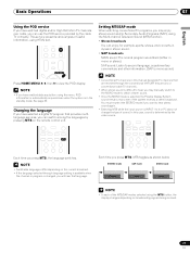
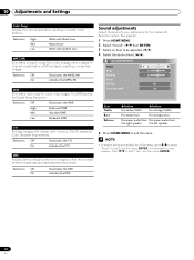
... Reset FOCUS Front Surround 2 0 0 Off Off Item Treble Bass Balance button For weaker treble button For stronger treble For weaker bass For stronger bass Decreases audio from Decreases audio from video images when a digital TV channel is watched or a DVD is played, resulting in noise-free images.
... Reset FOCUS Front Surround 2 0 0 Off Off Item Treble Bass Balance button For weaker treble button For stronger treble For weaker bass For stronger bass Decreases audio from Decreases audio from video images when a digital TV channel is watched or a DVD is played, resulting in noise-free images.
Owner's Manual
Page 43
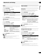
... ( / ) 4 Select the desired parameter. ( / ) Item Description Off Deactivates both TruBass and SRS effects. 5 Press HOME MENU to enjoy only audio, you can also select this function using a new (factory default) technology. dimensional sound. Power Control Power Control provides convenient functions for Front Surround. •...Disable Does not place the system into the standby mode when noise signals are present at the Media Receiver after a TV program finishes. 43 En TruBass Provides deep, rich bass using the Home menu when the input source is placed into the standby mode...
... ( / ) 4 Select the desired parameter. ( / ) Item Description Off Deactivates both TruBass and SRS effects. 5 Press HOME MENU to enjoy only audio, you can also select this function using a new (factory default) technology. dimensional sound. Power Control Power Control provides convenient functions for Front Surround. •...Disable Does not place the system into the standby mode when noise signals are present at the Media Receiver after a TV program finishes. 43 En TruBass Provides deep, rich bass using the Home menu when the input source is placed into the standby mode...
Owner's Manual
Page 50
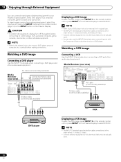
... OUT MONITOR OUT S-VIDEO VIDEO R-AUDIO-L S-VIDEO R-AUDIO-L IINNPUTT 33 Y CB/PB CR/PR INPUT 1 INPUT HDMI AV cable (commercially available) S-Video cable (commercially available) DVD player VCR Displaying a VCR image To watch a DVD image, press INPUT 1 on the remote control unit or press INPUT on the Plasma Display to select INPUT1. •...
... OUT MONITOR OUT S-VIDEO VIDEO R-AUDIO-L S-VIDEO R-AUDIO-L IINNPUTT 33 Y CB/PB CR/PR INPUT 1 INPUT HDMI AV cable (commercially available) S-Video cable (commercially available) DVD player VCR Displaying a VCR image To watch a DVD image, press INPUT 1 on the remote control unit or press INPUT on the Plasma Display to select INPUT1. •...
Owner's Manual
Page 51
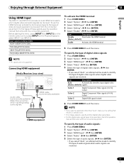
... no image appears, specify another digital video signal type. • For the digital video signal types to identify the type of audio signals when audio signals are not supported. Color-1 Digital Component Video signals (4:2:2) locked Color-2 Digital Component Video signals (4:4:4) locked Color-3 Digital RGB .../PB CR/PR INPUT 1 INPUT 3 HDMI Audio cable (commercially available) Make this connection when inputting analog audio signals. Before starting the menu, press INPUT 1 (or INPUT 3) on the remote control unit or press INPUT on the Plasma Display to exit the menu. HDMI cable (...
... no image appears, specify another digital video signal type. • For the digital video signal types to identify the type of audio signals when audio signals are not supported. Color-1 Digital Component Video signals (4:2:2) locked Color-2 Digital Component Video signals (4:4:4) locked Color-3 Digital RGB .../PB CR/PR INPUT 1 INPUT 3 HDMI Audio cable (commercially available) Make this connection when inputting analog audio signals. Before starting the menu, press INPUT 1 (or INPUT 3) on the remote control unit or press INPUT on the Plasma Display to exit the menu. HDMI cable (...

Owner's Manual
Page 52
...8226; If no sound is to select INPUT4. Media Receiver (front view) COMPONENT VIDEO Y CB / PB CR / PR INPUT 4 S-VIDEO VIDEO AUDIO L R AUDIO (STEREO) PC ANALOG RGB AV cable (commercially available) S-Video cable (commercially available) • The INPUT 4 terminals are to be inhibited. 1...the Plasma Display to be actually used. Avoiding unwanted feedback You can also record digital TV programs more information, see page 59. Specify the output terminal whose output is output, specify another audio signal type. • For the audio signal types to connect analog audio ...
...8226; If no sound is to select INPUT4. Media Receiver (front view) COMPONENT VIDEO Y CB / PB CR / PR INPUT 4 S-VIDEO VIDEO AUDIO L R AUDIO (STEREO) PC ANALOG RGB AV cable (commercially available) S-Video cable (commercially available) • The INPUT 4 terminals are to be inhibited. 1...the Plasma Display to be actually used. Avoiding unwanted feedback You can also record digital TV programs more information, see page 59. Specify the output terminal whose output is output, specify another audio signal type. • For the audio signal types to connect analog audio ...
Owner's Manual
Page 53
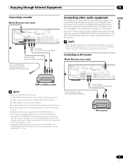
...other than external input sources. If your AV receiver. This allows audio such as digital TV broadcasting to be played in distorted images or noise. • Analog broadcasting signals are being input 5 Digital video and audio signals from INPUT 1, 2, or 4. Selecting an external input ... signals (INPUT 1, 2, and 4) are not sent to the MONITOR OUT terminals, select an input source (e.g., TV channel reception) on the recording equipment other audio equipment The digital audio output terminal (optical) on a VCR or DVD recorder connected to the MONITOR OUT (S-VIDEO) terminal. For more...
...other than external input sources. If your AV receiver. This allows audio such as digital TV broadcasting to be played in distorted images or noise. • Analog broadcasting signals are being input 5 Digital video and audio signals from INPUT 1, 2, or 4. Selecting an external input ... signals (INPUT 1, 2, and 4) are not sent to the MONITOR OUT terminals, select an input source (e.g., TV channel reception) on the recording equipment other audio equipment The digital audio output terminal (optical) on a VCR or DVD recorder connected to the MONITOR OUT (S-VIDEO) terminal. For more...
Owner's Manual
Page 54
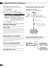
... two D-VHS recorders You can be recorded through i.LINK, you need to this PDP system to control one of the Media Receiver. The i.LINK terminals on the rear of up for the DIGITAL AUDIO output terminal (OPTICAL), depending on your AV receiver. 1 Press HOME MENU. ... ENTER) 3 Select "Digital Audio Out". ( / then ENTER) 4 Select "Dolby Digital" or "PCM". ( / then ENTER) Item Description PCM Always outputs in connection) that can be connected using a single i.LINK cable. you can record only digital TV programs. You cannot record conventional TV channels nor contents coming from ...
... two D-VHS recorders You can be recorded through i.LINK, you need to this PDP system to control one of the Media Receiver. The i.LINK terminals on the rear of up for the DIGITAL AUDIO output terminal (OPTICAL), depending on your AV receiver. 1 Press HOME MENU. ... ENTER) 3 Select "Digital Audio Out". ( / then ENTER) 4 Select "Dolby Digital" or "PCM". ( / then ENTER) Item Description PCM Always outputs in connection) that can be connected using a single i.LINK cable. you can record only digital TV programs. You cannot record conventional TV channels nor contents coming from ...
Owner's Manual
Page 55
.... Using i.LINK, those recorders cannot record conventional TV channels nor contents coming from that presents data coding and device authentication. • i.LINK may not allow copy-restricted video, audio, and other data to be copied from one of these D-VHS recorders (basic functions only). • Some D-VHS recorders connected... D-VHS recorder Displaying a D-VHS image To watch a D-VHS image, press i.LINK on the remote control unit or press INPUT on the Plasma Display to change the setting for data relay in use D-VHS tape. You can control one i.LINK device to play back digital...
.... Using i.LINK, those recorders cannot record conventional TV channels nor contents coming from that presents data coding and device authentication. • i.LINK may not allow copy-restricted video, audio, and other data to be copied from one of these D-VHS recorders (basic functions only). • Some D-VHS recorders connected... D-VHS recorder Displaying a D-VHS image To watch a D-VHS image, press i.LINK on the remote control unit or press INPUT on the Plasma Display to change the setting for data relay in use D-VHS tape. You can control one i.LINK device to play back digital...

Owner's Manual
Page 58
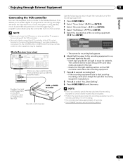
...computers in the menu. If the personal computer image does not come in clearly, you may not correctly function, depending on the Plasma Display to select "PC". • The PC terminals cannot be required for audiovisual equipment. Personal computer Displaying an image from ... some Macintosh computers. Media Receiver (front view) EC DATA ER ACQUISITION COMPONENT VIDEO Y CB / PB CR / PR INPUT 4 S-VIDEO VIDEO AUDIO L R AUDIO (STEREO) PC ANALOG RGB ø 3.5 mm stereo miniplug cable (commercially available) RGB cable (commercially available) Signal names for 15-pin mini ...
...computers in the menu. If the personal computer image does not come in clearly, you may not correctly function, depending on the Plasma Display to select "PC". • The PC terminals cannot be required for audiovisual equipment. Personal computer Displaying an image from ... some Macintosh computers. Media Receiver (front view) EC DATA ER ACQUISITION COMPONENT VIDEO Y CB / PB CR / PR INPUT 4 S-VIDEO VIDEO AUDIO L R AUDIO (STEREO) PC ANALOG RGB ø 3.5 mm stereo miniplug cable (commercially available) RGB cable (commercially available) Signal names for 15-pin mini ...
Owner's Manual
Page 59
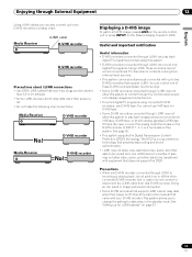
...the recording equipment is not in the standby mode is automatically switched on and the specified TV program is not recording. • The recording test takes approximately 10 seconds. • The PIONEER has been set the manufacture of the recording equipment: 1 Press HOME MENU. 2 Select... IN ANTENNA B ANTENNA/ CABLE A IN Cable CARD S-VIDEO INPUT 2 VIDEO R-AUDIO-L DIGITAL O OPTICA (TS) S400 VIDEO INPUT 1 COMPON R-AUDIO-L Y CB/ SERVICE ONLY OUT MONITOR OUT S-VIDEO VIDEO R-AUDIO-L S-VIDEO R-AUDIO-L IINNPUTT 33 Y CB/ (Once you have mistakenly connected it to the CONTROL ...
...the recording equipment is not in the standby mode is automatically switched on and the specified TV program is not recording. • The recording test takes approximately 10 seconds. • The PIONEER has been set the manufacture of the recording equipment: 1 Press HOME MENU. 2 Select... IN ANTENNA B ANTENNA/ CABLE A IN Cable CARD S-VIDEO INPUT 2 VIDEO R-AUDIO-L DIGITAL O OPTICA (TS) S400 VIDEO INPUT 1 COMPON R-AUDIO-L Y CB/ SERVICE ONLY OUT MONITOR OUT S-VIDEO VIDEO R-AUDIO-L S-VIDEO R-AUDIO-L IINNPUTT 33 Y CB/ (Once you have mistakenly connected it to the CONTROL ...


