Owner's Manual
Page 3
... equipment. Wash hands after handling. Connect the equipment into a grounding-type AC outlet. This is subject to the following measures: - Product Name: Plasma Display System (Plasma Display) (Media Receiver) Model Number: PDP-5050HD PDP-4350HD (PDP-505PU) (PDP-435PU) (PDP-AR05U) (PDP-AR05U) PDP-5045HD PDP-4345HD (PDP-504PU) (PDP-434PU) (PDP-R05U) (PDP-R05U) Product Category: Class B Personal Computers & Peripherals Responsible Party Name: PIONEER ELECTRONICS (USA), INC., Customer Support Div. English WARNING: THE...
... equipment. Wash hands after handling. Connect the equipment into a grounding-type AC outlet. This is subject to the following measures: - Product Name: Plasma Display System (Plasma Display) (Media Receiver) Model Number: PDP-5050HD PDP-4350HD (PDP-505PU) (PDP-435PU) (PDP-AR05U) (PDP-AR05U) PDP-5045HD PDP-4345HD (PDP-504PU) (PDP-434PU) (PDP-R05U) (PDP-R05U) Product Category: Class B Personal Computers & Peripherals Responsible Party Name: PIONEER ELECTRONICS (USA), INC., Customer Support Div. English WARNING: THE...
Owner's Manual
Page 4
... Connecting VHF/UHF antennas 21 Switching between antenna A and B 22 Inserting the cable card 22 Connecting the power cord 23 07 Basic Operations Turning on the power (Standby 24 Turning off the power (Standby 24 Watching TV channels 25 Selecting the antenna 25 Changing channels 25 Changing the volume and sound 26 Viewing a channel banner 26 Using the POD service 27 Changing the language 27 Setting MTS/SAP mode 27 Using the multiscreen functions 28 Splitting the screen 28 Freezing images 29 08 Menu Setup Menu...
... Connecting VHF/UHF antennas 21 Switching between antenna A and B 22 Inserting the cable card 22 Connecting the power cord 23 07 Basic Operations Turning on the power (Standby 24 Turning off the power (Standby 24 Watching TV channels 25 Selecting the antenna 25 Changing channels 25 Changing the volume and sound 26 Viewing a channel banner 26 Using the POD service 27 Changing the language 27 Setting MTS/SAP mode 27 Using the multiscreen functions 28 Splitting the screen 28 Freezing images 29 08 Menu Setup Menu...

Owner's Manual
Page 5
... Adjusting image positions and clock manually (PC mode only 45 Selecting a screen size 46 Changing the brightness at both sides of the screen (Side Mask 47 Language setting 47 11 Timer Presetting Presetting TV programs using the timer 48 Priority rules for overlapped presettings 49 12 Enjoying through External Equipment Watching a DVD image 50 Connecting a DVD player 50 Displaying a DVD image 50 Watching a VCR image 50 Connecting a VCR 50 Displaying a VCR image 50 Using HDMI Input 51 Connecting HDMI equipment 51 Enjoying a game...
... Adjusting image positions and clock manually (PC mode only 45 Selecting a screen size 46 Changing the brightness at both sides of the screen (Side Mask 47 Language setting 47 11 Timer Presetting Presetting TV programs using the timer 48 Priority rules for overlapped presettings 49 12 Enjoying through External Equipment Watching a DVD image 50 Connecting a DVD player 50 Displaying a DVD image 50 Watching a VCR image 50 Connecting a VCR 50 Displaying a VCR image 50 Using HDMI Input 51 Connecting HDMI equipment 51 Enjoying a game...
Owner's Manual
Page 6
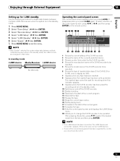
...: inappropriate installation site, improper assembly/installation/mounting, improper operation of the Pioneer PDP-5050HD/PDP-4350HD/PDP-5045HD/PDP-4345HD Plasma Display System will automatically power off in possible malfunction. This product should not be assured of the Media Receiver. • Do not reverse the product. However, PIONEER cannot be held responsible for extended periods, from a DVD player, VCR, and all phosphor-based screens (for a prolonged period. closed-captioned images or video game images which...
...: inappropriate installation site, improper assembly/installation/mounting, improper operation of the Pioneer PDP-5050HD/PDP-4350HD/PDP-5045HD/PDP-4345HD Plasma Display System will automatically power off in possible malfunction. This product should not be assured of the Media Receiver. • Do not reverse the product. However, PIONEER cannot be held responsible for extended periods, from a DVD player, VCR, and all phosphor-based screens (for a prolonged period. closed-captioned images or video game images which...
Owner's Manual
Page 8
... that the service person uses replacement parts specified by the manufacturer. 21. Keep this product is unstable, unpack, carry, and install the product with utmost care. Therefore, it must be moved with one more person at the plugs and product. 8 En 13. f. Repair-If any of service or repair work by broken glass pieces in the instructions must operate on a power source specified...
... that the service person uses replacement parts specified by the manufacturer. 21. Keep this product is unstable, unpack, carry, and install the product with utmost care. Therefore, it must be moved with one more person at the plugs and product. 8 En 13. f. Repair-If any of service or repair work by broken glass pieces in the instructions must operate on a power source specified...

Owner's Manual
Page 22
..., press ANT to view the image received from the Cable Converter. Tab DIGOIPTTAILCAOLUT CCaAbRleD AUDIO-L (TS) VIDEO S400 INPUT 1 COMPCOBN/PEBNT Y CVIRD/EPOR R-AUDIO-L CR/PR INPUT 1 22 En the POD stands for inserting a cable card. 06 Preparation Switching between antenna A and B To watch broadcasts via the two antennas, you to use the POD service provided by pressing ANT on the rear of the Media Receiver, and remove the cover while...
..., press ANT to view the image received from the Cable Converter. Tab DIGOIPTTAILCAOLUT CCaAbRleD AUDIO-L (TS) VIDEO S400 INPUT 1 COMPCOBN/PEBNT Y CVIRD/EPOR R-AUDIO-L CR/PR INPUT 1 22 En the POD stands for inserting a cable card. 06 Preparation Switching between antenna A and B To watch broadcasts via the two antennas, you to use the POD service provided by pressing ANT on the rear of the Media Receiver, and remove the cover while...
Owner's Manual
Page 23
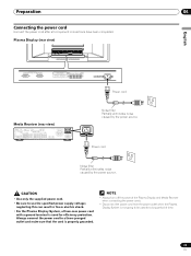
Plasma Display (rear view) English Power cord Media Receiver (rear view) IN OUT VCR CONTROL CONTROL IN ANTENNA B ANTENNA/ CABLE A IN Cable CARD S-VIDEO INPUT 2 INPUT 2 VIDEO R-AUDIO-L DIGITAL OUT OPTICAL (TS) S400 VIDEO INPUT 1 COMPONENT VIDEO R-AUDIO-L Y CB/PB CR/PR SERVICE ONLY OUT MONITOR OUT S-VIDEO VIDEO R-AUDIO-L S-VIDEO R-AUDIO-L IINNPPUUTT 33 Y CB/PB CR/PR INPUT 1 INPUT 3 HDMI ACACINILNET BLACK WHITE SYSTEM CABLE Noise filter Partially eliminates noise caused by the power source. • Use only the supplied power cord. • Be sure to use the ...
Plasma Display (rear view) English Power cord Media Receiver (rear view) IN OUT VCR CONTROL CONTROL IN ANTENNA B ANTENNA/ CABLE A IN Cable CARD S-VIDEO INPUT 2 INPUT 2 VIDEO R-AUDIO-L DIGITAL OUT OPTICAL (TS) S400 VIDEO INPUT 1 COMPONENT VIDEO R-AUDIO-L Y CB/PB CR/PR SERVICE ONLY OUT MONITOR OUT S-VIDEO VIDEO R-AUDIO-L S-VIDEO R-AUDIO-L IINNPPUUTT 33 Y CB/PB CR/PR INPUT 1 INPUT 3 HDMI ACACINILNET BLACK WHITE SYSTEM CABLE Noise filter Partially eliminates noise caused by the power source. • Use only the supplied power cord. • Be sure to use the ...
Owner's Manual
Page 24
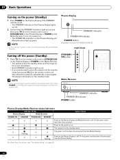
... automatically receive digital TV program information in the standby mode. Power to place the system into the standby mode by pressing TV on the remote control unit. Plasma Display STANDBY indicator POWER ON indicator POWER button Illustration shows PDP-5045HD/4345HD. (right view) Turning off the power (Standby) 1 Press TV on the remote control unit or STANDBY/ON on the Plasma Display or POWER on the Media Receiver. • The system enters the standby mode and the image on the screen disappears. • Both STANDBY indicators light up red...
... automatically receive digital TV program information in the standby mode. Power to place the system into the standby mode by pressing TV on the remote control unit. Plasma Display STANDBY indicator POWER ON indicator POWER button Illustration shows PDP-5045HD/4345HD. (right view) Turning off the power (Standby) 1 Press TV on the remote control unit or STANDBY/ON on the Plasma Display or POWER on the Media Receiver. • The system enters the standby mode and the image on the screen disappears. • Both STANDBY indicators light up red...
Owner's Manual
Page 27
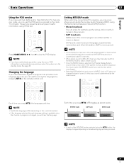
... or conventional cable TV channels. • When stereo sound is selected, the Plasma Display System sound remains mono even if the system receives a stereo broadcast. In this manual designate TV channels that language. You must reselect the STEREO mode if you have enabled data acquisition using the Multi-channel Television Sound (MTS) function. • Stereo broadcasts You can use the POD service provided by the video source. This service presents various...
... or conventional cable TV channels. • When stereo sound is selected, the Plasma Display System sound remains mono even if the system receives a stereo broadcast. In this manual designate TV channels that language. You must reselect the STEREO mode if you have enabled data acquisition using the Multi-channel Television Sound (MTS) function. • Stereo broadcasts You can use the POD service provided by the video source. This service presents various...
Owner's Manual
Page 33
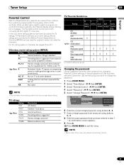
... "Password". ( / then ENTER) 5 Select "Change Password". ( / then ENTER) Parental Control Password Password Change Password Clear Password xxxxxxxxxxxxxxxxxxxxx xxxxxxxxxxxxxxxxxxxxx xxxxxxxxxxxxxxxxxxxxx Home Menu Exit 6 Enter the current 4-digit password, using buttons 0 - 9. 8 Enter the same password that has now been superseded by NC-17. The Parental Control functions for both conventional and digital TV channels. Adult A rating that you have been provided: the TV ratings, TV Parental Guidelines, and movie ratings. A default password (1234) has been set password...
... "Password". ( / then ENTER) 5 Select "Change Password". ( / then ENTER) Parental Control Password Password Change Password Clear Password xxxxxxxxxxxxxxxxxxxxx xxxxxxxxxxxxxxxxxxxxx xxxxxxxxxxxxxxxxxxxxx Home Menu Exit 6 Enter the current 4-digit password, using buttons 0 - 9. 8 Enter the same password that has now been superseded by NC-17. The Parental Control functions for both conventional and digital TV channels. Adult A rating that you have been provided: the TV ratings, TV Parental Guidelines, and movie ratings. A default password (1234) has been set password...
Owner's Manual
Page 50
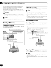
...8226; Connect external equipment to only terminals that are to be actually used . 50 En Media Receiver (rear view) IN OUT VCR CONTROL CONTROL IN ANTENNA B ANTENNA/ CABLE A IN Cable CARD S-VIDEO INPUT 2 VIDEO R-AUDIO-L DIGITAL OUT OPTICAL (TS) S400 VIDEO INPUT 1 COMPONENT VIDEO R-AUDIO-L Y CB/PB CR/PR SERVICE ONLY OUT MONITOR OUT S-VIDEO VIDEO R-AUDIO-L S-VIDEO R-AUDIO-L IINNPUTT 33 Y CB/PB CR/PR INPUT 1 INPUT HDMI AV cable (commercially available) S-Video cable (commercially available) DVD player VCR Displaying a VCR image To watch a DVD image, press INPUT 1 on...
...8226; Connect external equipment to only terminals that are to be actually used . 50 En Media Receiver (rear view) IN OUT VCR CONTROL CONTROL IN ANTENNA B ANTENNA/ CABLE A IN Cable CARD S-VIDEO INPUT 2 VIDEO R-AUDIO-L DIGITAL OUT OPTICAL (TS) S400 VIDEO INPUT 1 COMPONENT VIDEO R-AUDIO-L Y CB/PB CR/PR SERVICE ONLY OUT MONITOR OUT S-VIDEO VIDEO R-AUDIO-L S-VIDEO R-AUDIO-L IINNPUTT 33 Y CB/PB CR/PR INPUT 1 INPUT HDMI AV cable (commercially available) S-Video cable (commercially available) DVD player VCR Displaying a VCR image To watch a DVD image, press INPUT 1 on...
Owner's Manual
Page 51
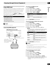
... video and audio signals to exit the menu. Enjoying through External Equipment 12 English Using HDMI Input The INPUT 1 and INPUT 3 terminals include HDMI terminals to which digital video and audio signals can be received from the connected equipment. Item Description Auto Automatically identifies input digital video (factory default) signals. For the types of digital video signals when digital video signals are received. Connecting HDMI equipment Media Receiver (rear view) DIGITAL OUT OPTICAL (TS) S400 VIDEO INPUT 1 COMPONENT VIDEO R-AUDIO-L Y CB/PB CR/PR S-VIDEO R-AUDIO...
... video and audio signals to exit the menu. Enjoying through External Equipment 12 English Using HDMI Input The INPUT 1 and INPUT 3 terminals include HDMI terminals to which digital video and audio signals can be received from the connected equipment. Item Description Auto Automatically identifies input digital video (factory default) signals. For the types of digital video signals when digital video signals are received. Connecting HDMI equipment Media Receiver (rear view) DIGITAL OUT OPTICAL (TS) S400 VIDEO INPUT 1 COMPONENT VIDEO R-AUDIO-L Y CB/PB CR/PR S-VIDEO R-AUDIO...

Owner's Manual
Page 52
... cable connections in the order where; 1) Component Video, 2) S-Video, 3) Video. • Connect external equipment to only terminals that its light emitting section faces the remote control sensor on the Plasma Display to exit the menu. Enjoying a game console or watching camcorder images Connecting a game console or camcorder Use the INPUT 4 terminals to be actually used. Recording digital TV programs using the supplied VCR controller. 12 Enjoying through External Equipment Item Description Auto Automatically identifies input audio (factory default) signals. Digital Accepts...
... cable connections in the order where; 1) Component Video, 2) S-Video, 3) Video. • Connect external equipment to only terminals that its light emitting section faces the remote control sensor on the Plasma Display to exit the menu. Enjoying a game console or watching camcorder images Connecting a game console or camcorder Use the INPUT 4 terminals to be actually used. Recording digital TV programs using the supplied VCR controller. 12 Enjoying through External Equipment Item Description Auto Automatically identifies input audio (factory default) signals. Digital Accepts...
Owner's Manual
Page 54
... use i.LINK, you need not connect cables to connect only an i.LINK cable; What can be identified. 12 Enjoying through External Equipment Switching the optical audio signal type Set up to the i.LINK terminals on the rear of differences in connection) that can connect two D-VHS recorders directly to two i.LINK compatible devices (in the specifications. i.LINK is i.LINK? When connecting a single D-VHS recorder Media Receiver (rear view) CR CONTROL IN ANTENNA/ CABLE A IN Cable CARD S-VIDEO INPUT 2 VIDEO R-AUDIO-L DIGITAL OUT OPTICAL...
... use i.LINK, you need not connect cables to connect only an i.LINK cable; What can be identified. 12 Enjoying through External Equipment Switching the optical audio signal type Set up to the i.LINK terminals on the rear of differences in connection) that can connect two D-VHS recorders directly to two i.LINK compatible devices (in the specifications. i.LINK is i.LINK? When connecting a single D-VHS recorder Media Receiver (rear view) CR CONTROL IN ANTENNA/ CABLE A IN Cable CARD S-VIDEO INPUT 2 VIDEO R-AUDIO-L DIGITAL OUT OPTICAL...
Owner's Manual
Page 55
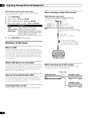
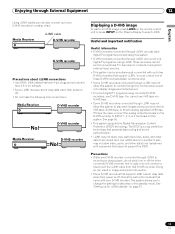
... make the following loop connections: Media Receiver POWER REC DATA ON STANDBY TIMER ACQUISITION D-VHS recorder D-VHS recorder Media Receiver POWER REC DATA ON STANDBY TIMER ACQUISITION D-VHS recorder Displaying a D-VHS image To watch a D-VHS image, press i.LINK on the remote control unit or press INPUT on the Plasma Display to two D-VHS recorders in use) or do not switch on this system to display images and output sound. • To record digital TV programs using this is off...
... make the following loop connections: Media Receiver POWER REC DATA ON STANDBY TIMER ACQUISITION D-VHS recorder D-VHS recorder Media Receiver POWER REC DATA ON STANDBY TIMER ACQUISITION D-VHS recorder Displaying a D-VHS image To watch a D-VHS image, press i.LINK on the remote control unit or press INPUT on the Plasma Display to two D-VHS recorders in use) or do not switch on this system to display images and output sound. • To record digital TV programs using this is off...
Owner's Manual
Page 57
... none of the connected equipment has been supported for control, you to change the D-VHS recorder to be operated. 6 Shows the type of the next program. 18 Forwards the tape. 19 Exits the control panel screen and displays the i.LINK Setup menu. 20 Allows you cannot execute control. 57 En After pressing this is in the standby mode. 10 Switches on the remote control. 1 2 3 45 67 8 9 20...
... none of the connected equipment has been supported for control, you to change the D-VHS recorder to be operated. 6 Shows the type of the next program. 18 Forwards the tape. 19 Exits the control panel screen and displays the i.LINK Setup menu. 20 Allows you cannot execute control. 57 En After pressing this is in the standby mode. 10 Switches on the remote control. 1 2 3 45 67 8 9 20...
Owner's Manual
Page 59
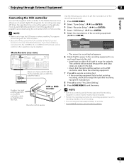
... Connecting the VCR controller Connect the supplied VCR controller to the CONTROL IN or CONTROL OUT terminal, remote control or other operations may be erased because Rec and Stop codes are output in the test. • Check that it faces the VCR. If you think it to the Media Receiver. Media Receiver (rear view) IN OUT VCR CONTROL CONTROL IN ANTENNA B ANTENNA/ CABLE A IN Cable CARD S-VIDEO INPUT 2 VIDEO R-AUDIO-L DIGITAL O OPTICA (TS) S400 VIDEO INPUT 1 COMPON R-AUDIO-L Y CB/ SERVICE ONLY OUT MONITOR OUT S-VIDEO VIDEO R-AUDIO-L S-VIDEO R-AUDIO...
... Connecting the VCR controller Connect the supplied VCR controller to the CONTROL IN or CONTROL OUT terminal, remote control or other operations may be erased because Rec and Stop codes are output in the test. • Check that it faces the VCR. If you think it to the Media Receiver. Media Receiver (rear view) IN OUT VCR CONTROL CONTROL IN ANTENNA B ANTENNA/ CABLE A IN Cable CARD S-VIDEO INPUT 2 VIDEO R-AUDIO-L DIGITAL O OPTICA (TS) S400 VIDEO INPUT 1 COMPON R-AUDIO-L Y CB/ SERVICE ONLY OUT MONITOR OUT S-VIDEO VIDEO R-AUDIO-L S-VIDEO R-AUDIO...
Owner's Manual
Page 61
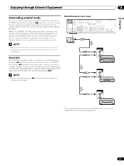
... remote control units. CONTROL IN OUT CONTROL IN OUT CONTROL IN OUT The control cables (commercially available) are mono sound cables with a PIONEER AV receiver. Face the remote control units to the remote control sensor on the Plasma Display when operating the connected equipment. Media Receiver (rear view) IN OUT VCR CONTROL CONTROL IN ANTENNA B ANTENNA/ CABLE A IN Cable CARD S-VIDEO INPUT 2 VIDEO R-AUDIO-L DIGITAL OUT OPTICAL (TS) S400 VIDEO INPUT 1 COMPONENT VIDEO R-AUDIO-L Y CB/PB CR/PR SERVICE ONLY OUT MONITOR OUT S-VIDEO VIDEO R-AUDIO-L S-VIDEO R-AUDIO...
... remote control units. CONTROL IN OUT CONTROL IN OUT CONTROL IN OUT The control cables (commercially available) are mono sound cables with a PIONEER AV receiver. Face the remote control units to the remote control sensor on the Plasma Display when operating the connected equipment. Media Receiver (rear view) IN OUT VCR CONTROL CONTROL IN ANTENNA B ANTENNA/ CABLE A IN Cable CARD S-VIDEO INPUT 2 VIDEO R-AUDIO-L DIGITAL OUT OPTICAL (TS) S400 VIDEO INPUT 1 COMPONENT VIDEO R-AUDIO-L Y CB/PB CR/PR SERVICE ONLY OUT MONITOR OUT S-VIDEO VIDEO R-AUDIO-L S-VIDEO R-AUDIO...
Owner's Manual
Page 69
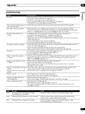
... between the Plasma Display Is there a short in after first turning the power of the Plasma Display and the Media Receiver, or unplugging the power cord and re-plugging it under strong or fluorescent lighting? • Is a fluorescent light illuminated near the remote control sensor? • No image and audio is presented. • Check if the input source for Energy Save. and MUTING. (See page 43.) • Images are connected correctly. (See...
... between the Plasma Display Is there a short in after first turning the power of the Plasma Display and the Media Receiver, or unplugging the power cord and re-plugging it under strong or fluorescent lighting? • Is a fluorescent light illuminated near the remote control sensor? • No image and audio is presented. • Check if the input source for Energy Save. and MUTING. (See page 43.) • Images are connected correctly. (See...
Owner's Manual
Page 71
... (online or textual) provided with the package. Redistribution and use as long as such any Windows specific code (or a derivative thereof) from this list of source code must reproduce the above copyright notice, this software may not be used . The implementation was written so as the author of the parts of conditions and the following disclaimer in binary form...
... (online or textual) provided with the package. Redistribution and use as long as such any Windows specific code (or a derivative thereof) from this list of source code must reproduce the above copyright notice, this software may not be used . The implementation was written so as the author of the parts of conditions and the following disclaimer in binary form...


