Owner's Manual
Page 3
... Remove the Included Stand ...16 2.2.2 Connect the Speaker Cables ...22 2.3 Wall/Ceiling Mounting...23 2.4 Mount the Flat Panel TV ...24 2.5 Attach the Color Sensor ...26 2.6 Connect to Broadcast TV & Other Devices (DVR, Receiver, BDR, etc 29 2.6.1 Add Analog (conventional) and Digital TV Channels 29 2.6.2 Connect Your Other Pioneer Equipment...29 2.6.3 Connect the Power Cord to...
... Remove the Included Stand ...16 2.2.2 Connect the Speaker Cables ...22 2.3 Wall/Ceiling Mounting...23 2.4 Mount the Flat Panel TV ...24 2.5 Attach the Color Sensor ...26 2.6 Connect to Broadcast TV & Other Devices (DVR, Receiver, BDR, etc 29 2.6.1 Add Analog (conventional) and Digital TV Channels 29 2.6.2 Connect Your Other Pioneer Equipment...29 2.6.3 Connect the Power Cord to...
Owner's Manual
Page 6
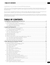
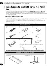
... accessories included to the ELITE Series Flat Panel TVs The Pioneer ELITE Series Flat Panel TV models include the 60-inch PRO-151FD and the 50-inch PRO-111FD (screen sizes measured diagonally). Service contact information is missing, please contact your panel. You will need a Philips screwdriver when mounting the speaker and attaching the stand. 01 Introduction to...
... accessories included to the ELITE Series Flat Panel TVs The Pioneer ELITE Series Flat Panel TV models include the 60-inch PRO-151FD and the 50-inch PRO-111FD (screen sizes measured diagonally). Service contact information is missing, please contact your panel. You will need a Philips screwdriver when mounting the speaker and attaching the stand. 01 Introduction to...
Owner's Manual
Page 7
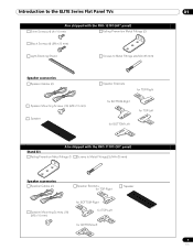
...TVs 01 Also shipped with the PRO-151FD (60" panel) Silver Screws (4) (4×10 mm) Falling Prevention Metal Fittings (2) Black Screws (4) (M6×20 mm) Light-Blocking Shield Screws to Metal Fittings (4) (M4×35 mm) Speaker accessories Speaker Cables (2) Speaker Mounting Screws (16) (M5×10 mm) Speaker Speaker... Brackets for TOP-Right for BOTTOM-Right for TOP-Left for BOTTOM-Left Also shipped with the PRO-111FD (50" panel) Stand kit Falling...
...TVs 01 Also shipped with the PRO-151FD (60" panel) Silver Screws (4) (4×10 mm) Falling Prevention Metal Fittings (2) Black Screws (4) (M6×20 mm) Light-Blocking Shield Screws to Metal Fittings (4) (M4×35 mm) Speaker accessories Speaker Cables (2) Speaker Mounting Screws (16) (M5×10 mm) Speaker Speaker... Brackets for TOP-Right for BOTTOM-Right for TOP-Left for BOTTOM-Left Also shipped with the PRO-111FD (50" panel) Stand kit Falling...
Owner's Manual
Page 9
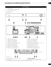
...OUT terminal 23 -DIGITAL OUT terminal (Optical) 24 -SPEAKERS (right/left) terminal (PRO-151FD) (lower bank) 25 26 27 28 25 -Speakers (R) terminal (speaker side) 26 -Color Sensor 27 -Power On button 28 -Speakers (L) terminal (speaker side) Terminals on side and rear panels are common ...to the ELITE Series Flat Panel TVs 01 1 - INPUT 4 terminal (HDMI) 7 - ...
...OUT terminal 23 -DIGITAL OUT terminal (Optical) 24 -SPEAKERS (right/left) terminal (PRO-151FD) (lower bank) 25 26 27 28 25 -Speakers (R) terminal (speaker side) 26 -Color Sensor 27 -Power On button 28 -Speakers (L) terminal (speaker side) Terminals on side and rear panels are common ...to the ELITE Series Flat Panel TVs 01 1 - INPUT 4 terminal (HDMI) 7 - ...
Owner's Manual
Page 15
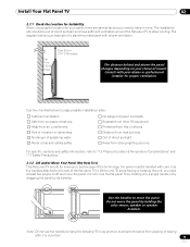
...sunlight and have sufficient ventilation around the flat panel TV to lift the unit. Do not move the flat panel TV by holding only a single handle or by dragging the panel by holding the color sensor, speaker or speaker brackets. The installation site should be handled with proper... "7.2 Physical Location & Temperature Considerations" and "7.7 Safety Precautions." 2.1.2 Lift and/or Move Your Panel (the How To's) This flat panel TV is built for proper ventilation. The diagram below to prevent the panel from strong lighting sources For specific cautions and safety information, refer to...
...sunlight and have sufficient ventilation around the flat panel TV to lift the unit. Do not move the flat panel TV by holding only a single handle or by dragging the panel by holding the color sensor, speaker or speaker brackets. The installation site should be handled with proper... "7.2 Physical Location & Temperature Considerations" and "7.7 Safety Precautions." 2.1.2 Lift and/or Move Your Panel (the How To's) This flat panel TV is built for proper ventilation. The diagram below to prevent the panel from strong lighting sources For specific cautions and safety information, refer to...
Owner's Manual
Page 16
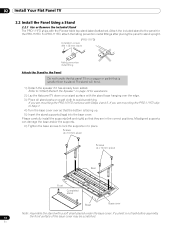
... Rear Front Completed stand Sheet Base cover Note: Assemble the stand with the Pioneer table top stand (stand) attached. For PRO-111FD, attach the falling prevention metal fittings after placing the panel to stand upright. (PRO-111FD) Installation screws (M4 × 35 mm: black) Falling prevention metal... TV 2.2 Install the Panel Using a Stand 2.2.1 Use or Remove the Included Stand The PRO-111FD ships with a soft sheet placed under the base cover. Attach the included stand to place. Refer to "Attach/Detach the Speaker" on page 19 for the PRO-151FD. If you are mounting the PRO...
... Rear Front Completed stand Sheet Base cover Note: Assemble the stand with the Pioneer table top stand (stand) attached. For PRO-111FD, attach the falling prevention metal fittings after placing the panel to stand upright. (PRO-111FD) Installation screws (M4 × 35 mm: black) Falling prevention metal... TV 2.2 Install the Panel Using a Stand 2.2.1 Use or Remove the Included Stand The PRO-111FD ships with a soft sheet placed under the base cover. Attach the included stand to place. Refer to "Attach/Detach the Speaker" on page 19 for the PRO-151FD. If you are mounting the PRO...
Owner's Manual
Page 19
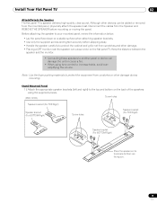
... scratches and other damage. • Placing a CRT monitor near the speaker can cause a blur on the flat panel TV. Install Your Flat Panel TV 02 Attach/Detach the Speaker The flat panel TV's speaker delivers high-quality, clear sound. Although other damage during mounting. Disconnect ... panel face down on the back of the speakers using the supplied screws. (PRO-151FD) Screw holes Speaker bracket (For TOP-Right) Speaker bracket (For BOTTOM-Right) Screw holes Speaker bracket (For TOP-Right) Speaker bracket (For BOTTOM-Right) Place the speaker so its terminals (bottom) are facing you....
... scratches and other damage. • Placing a CRT monitor near the speaker can cause a blur on the flat panel TV. Install Your Flat Panel TV 02 Attach/Detach the Speaker The flat panel TV's speaker delivers high-quality, clear sound. Although other damage during mounting. Disconnect ... panel face down on the back of the speakers using the supplied screws. (PRO-151FD) Screw holes Speaker bracket (For TOP-Right) Speaker bracket (For BOTTOM-Right) Screw holes Speaker bracket (For TOP-Right) Speaker bracket (For BOTTOM-Right) Place the speaker so its terminals (bottom) are facing you....
Owner's Manual
Page 20
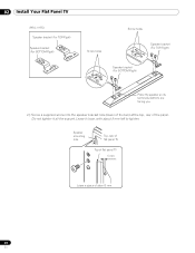
Leave it all the way yet. 02 Install Your Flat Panel TV (PRO-111FD) Speaker bracket (For TOP-Right) Speaker bracket (For BOTTOM-Right) Screw holes Screw holes Speaker bracket (For TOP-Right) Speaker bracket (For BOTTOM-Right) Place the speaker so its terminals (bottom) are facing you. 2 ) Screw a supplied screw into the speaker bracket hole (lower of the two) at the top, rear of about 5 mm left to tighten. Do not tighten it loose, with about 5 mm 20 En Speaker mounting hole Top, rear of flat panel TV Top of flat panel TV 5 mm Leave a space of the panel.
Leave it all the way yet. 02 Install Your Flat Panel TV (PRO-111FD) Speaker bracket (For TOP-Right) Speaker bracket (For BOTTOM-Right) Screw holes Screw holes Speaker bracket (For TOP-Right) Speaker bracket (For BOTTOM-Right) Place the speaker so its terminals (bottom) are facing you. 2 ) Screw a supplied screw into the speaker bracket hole (lower of the two) at the top, rear of about 5 mm left to tighten. Do not tighten it loose, with about 5 mm 20 En Speaker mounting hole Top, rear of flat panel TV Top of flat panel TV 5 mm Leave a space of the panel.
Owner's Manual
Page 21
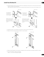
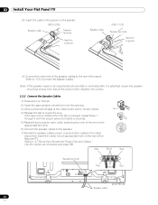
... hole over the screw, lower the speaker. Install Your Flat Panel TV 02 3 ) Hang the speaker bracket on the screw at the top and bottom for each speaker. (PRO-151FD) (PRO-111FD) 6 ) Pass the supplied speaker cable between the speaker and the panel (below the speaker bracket) from below. 7 ) Connect the speaker cables to the speaker. Tighten with the provided screw the...
... hole over the screw, lower the speaker. Install Your Flat Panel TV 02 3 ) Hang the speaker bracket on the screw at the top and bottom for each speaker. (PRO-151FD) (PRO-111FD) 6 ) Pass the supplied speaker cable between the speaker and the panel (below the speaker bracket) from below. 7 ) Connect the speaker cables to the speaker. Tighten with the provided screw the...
Owner's Manual
Page 22
... the groove on the rear of the flat panel TV. Adjust the position then retighten the screws. 2.2.2 Connect the Speaker Cables 1 ) Press down on the tab. 2 ) Insert the appropriately colored wire into an appropriate hole on the speaker. (PRO-151FD) Speaker cable Speaker terminal Insertion in groove Speaker cable (PRO-111FD) Speaker terminal Insertion in groove 9 ) Connect the other end...
... the groove on the rear of the flat panel TV. Adjust the position then retighten the screws. 2.2.2 Connect the Speaker Cables 1 ) Press down on the tab. 2 ) Insert the appropriately colored wire into an appropriate hole on the speaker. (PRO-151FD) Speaker cable Speaker terminal Insertion in groove Speaker cable (PRO-111FD) Speaker terminal Insertion in groove 9 ) Connect the other end...
Owner's Manual
Page 23
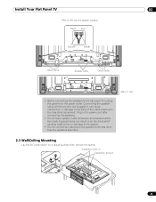
... to the speaker terminals other equipment. Connecting the speaker cable with the speaker installed Black Gray Black Red Cable clamp Speaker cable Cable clamp • Before connecting the speakers to the flat panel TV, unplug the panel from the power outlet. Installation bolts (1) Installation bolts (2) 23 En Install Your Flat Panel TV 02 PRO-151FD with the...
... to the speaker terminals other equipment. Connecting the speaker cable with the speaker installed Black Gray Black Red Cable clamp Speaker cable Cable clamp • Before connecting the speakers to the flat panel TV, unplug the panel from the power outlet. Installation bolts (1) Installation bolts (2) 23 En Install Your Flat Panel TV 02 PRO-151FD with the...
Owner's Manual
Page 24
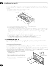
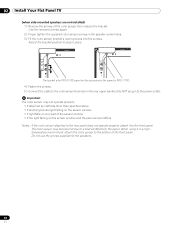
... using a stand, stabilize the panel to hang the panel on the flat panel TV for available ports and terminals. Follow the steps below . 1 ) Attach the hooks to the panel (see page 21). (PRO-111FD) 3 ) Connect the speaker cables to the speakers then to the mounting holes on the composition and thickness of the panel...
... using a stand, stabilize the panel to hang the panel on the flat panel TV for available ports and terminals. Follow the steps below . 1 ) Attach the hooks to the panel (see page 21). (PRO-111FD) 3 ) Connect the speaker cables to the speakers then to the mounting holes on the composition and thickness of the panel...

Owner's Manual
Page 27
... sensor may become hot due to the front panel. Adjust the color sensor/speaker bracket positions so as to the rear panel differ depending on the rear upper bank but the procedure is for PRO-151FD panel but do NOT plug in to the power outlet. Use the removed screws... again. (Bracket for PRO-111FD. 4 ) Fasten the screws. 5 ) Connect the cable to the color sensor terminal on the panel with or without sidemounted speakers. (when side-mounted speakers are installed) 1 ) Remove the screws of the color sensor then replace the bracket. Install Your Flat Panel TV 02 Attach the Color ...
... sensor may become hot due to the front panel. Adjust the color sensor/speaker bracket positions so as to the rear panel differ depending on the rear upper bank but the procedure is for PRO-151FD panel but do NOT plug in to the power outlet. Use the removed screws... again. (Bracket for PRO-111FD. 4 ) Fasten the screws. 5 ) Connect the cable to the color sensor terminal on the panel with or without sidemounted speakers. (when side-mounted speakers are installed) 1 ) Remove the screws of the color sensor then replace the bracket. Install Your Flat Panel TV 02 Attach the Color ...
Owner's Manual
Page 28
The bracket is for PRO-151FD panel but do NOT plug in to stay in place. Do not use the screws supplied for PRO-111FD. 4 ) Fasten the screws. 5 ) Connect the cable to the color sensor terminal on the sensor window and the panel screen differs Notes: If the color ... sensor window • if the light falling on the rear upper bank but the procedure is the same for the speakers. 28 En 02 Install Your Flat Panel TV (when side-mounted speakers are not installed) 1 ) Remove the screws of the front panel. Use the removed screws again. 2 ) Finger tighten the supplied color...
The bracket is for PRO-151FD panel but do NOT plug in to stay in place. Do not use the screws supplied for PRO-111FD. 4 ) Fasten the screws. 5 ) Connect the cable to the color sensor terminal on the sensor window and the panel screen differs Notes: If the color ... sensor window • if the light falling on the rear upper bank but the procedure is the same for the speakers. 28 En 02 Install Your Flat Panel TV (when side-mounted speakers are not installed) 1 ) Remove the screws of the front panel. Use the removed screws again. 2 ) Finger tighten the supplied color...
Owner's Manual
Page 32
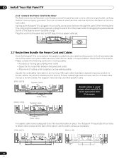
... plug it in place. Although rubber bands are too long. PRO-151FD PRO-111FD 32 En The cord includes a noise filter that reduces electrical interference from the power outlet. T T W W 2.7 Route then Bundle the Power Cord and Cables Once the flat panel TV is mounted and the speaker is drawn through the panel. Your flat panel...the panel from the wall outlet. Always connect the panel's power cord to break down too quickly. Unplugging the panel extends the life of the plasma as well as the flat panel TV is plugged in to bundle cables. Use the cable clamps as necessary.
... plug it in place. Although rubber bands are too long. PRO-151FD PRO-111FD 32 En The cord includes a noise filter that reduces electrical interference from the power outlet. T T W W 2.7 Route then Bundle the Power Cord and Cables Once the flat panel TV is mounted and the speaker is drawn through the panel. Your flat panel...the panel from the wall outlet. Always connect the panel's power cord to break down too quickly. Unplugging the panel extends the life of the plasma as well as the flat panel TV is plugged in to bundle cables. Use the cable clamps as necessary.
Owner's Manual
Page 121
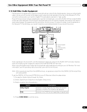
... back in the PCM format regardless of the flat panel TV. To set the DIGITAL OUT terminal (OPTICAL) for the PCM format (default) outputs in high quality. However, this method may still experience some delay between the speakers and the sound from the submenu. AV cable (commercially ... output terminal (optical) on the flat panel TV. Use Other Equipment With Your Flat Panel TV 05 5.12 Add Other Audio Equipment The flat panel TV's digital audio output terminal (optical) can output Dolby Digital signals. To reduce the delay, mute the speakers on the rear of signal type 4 ) ...
... back in the PCM format regardless of the flat panel TV. To set the DIGITAL OUT terminal (OPTICAL) for the PCM format (default) outputs in high quality. However, this method may still experience some delay between the speakers and the sound from the submenu. AV cable (commercially ... output terminal (optical) on the flat panel TV. Use Other Equipment With Your Flat Panel TV 05 5.12 Add Other Audio Equipment The flat panel TV's digital audio output terminal (optical) can output Dolby Digital signals. To reduce the delay, mute the speakers on the rear of signal type 4 ) ...
Owner's Manual
Page 126
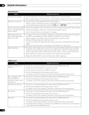
...the operating instructions that came with the equipment. • Check the connections between the panel and the HDMI equipment. • Confirm that speaker cables are correct. HDMI Control Issue HDMI Controls do not function Error message: "The device cannot be operated. For details, refer to burning.... Sound but no picture • Check if Picture Off is deactivated; only audio is wrong (one side • Check if the speaker cable connections have been reversed between the panel and the HDMI equipment. • Confirm that settings for a long period before switching to a...
...the operating instructions that came with the equipment. • Check the connections between the panel and the HDMI equipment. • Confirm that speaker cables are correct. HDMI Control Issue HDMI Controls do not function Error message: "The device cannot be operated. For details, refer to burning.... Sound but no picture • Check if Picture Off is deactivated; only audio is wrong (one side • Check if the speaker cable connections have been reversed between the panel and the HDMI equipment. • Confirm that settings for a long period before switching to a...
Owner's Manual
Page 145
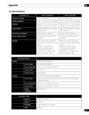
Side INPUT 3 VIDEO in, AUDIO in INPUT 7 HDMI in ** 145 En Appendix 08 8.3 Specifications Flat Panel TV Number of pixels Audio Amplifier Speaker Sound Effect On-Screen Languages Power Requirement Weight PRO-151FD (60") PRO-111FD (50") 1920 × 1080 pixels 1920 × 1080 pixels 18 W + 18 W (1 kHz, 10... English, French, Spanish 120 V AC, 60 Hz, 524 W (0.3 W Standby) 120 V AC, 60 Hz, 436 W (0.2 W Standby) Main unit: 51.0 kg (112.4 lbs) Stand: 6.1 kg (13.4 lbs) (including bolts) Speaker: 4.1 kg (9.0 lbs) (including cables, speaker brackets and screws) Color Sensor: 0.1 kg...
Side INPUT 3 VIDEO in, AUDIO in INPUT 7 HDMI in ** 145 En Appendix 08 8.3 Specifications Flat Panel TV Number of pixels Audio Amplifier Speaker Sound Effect On-Screen Languages Power Requirement Weight PRO-151FD (60") PRO-111FD (50") 1920 × 1080 pixels 1920 × 1080 pixels 18 W + 18 W (1 kHz, 10... English, French, Spanish 120 V AC, 60 Hz, 524 W (0.3 W Standby) 120 V AC, 60 Hz, 436 W (0.2 W Standby) Main unit: 51.0 kg (112.4 lbs) Stand: 6.1 kg (13.4 lbs) (including bolts) Speaker: 4.1 kg (9.0 lbs) (including cables, speaker brackets and screws) Color Sensor: 0.1 kg...
Owner's Manual
Page 146
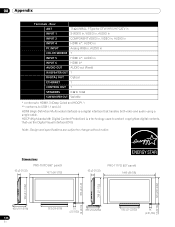
...subject to protect copyrighted digital contents that handles both video and audio using a single cable. 08 Appendix Terminals - Dimensions PRO-151FD (60" panel) 93 (3-21/32) 1677 (66-1/32) 93 (3-21/32) PRO-111FD (50" panel) 1445 (56-7/8) 723 (28-15/32) 788 (73818-1/32) 876 (34-1/2) 953 (... 1 INPUT 5 HDMI in*, AUDIO in INPUT 6 HDMI in* AUDIO OUT AUDIO out (Fixed) IR REPEATER OUT 1 DIGITAL OUT Optical ETHERNET 1 CONTROL OUT 1 SPEAKERS 6 Ω to 16 Ω SUB WOOFER OUT Variable * conforms to HDMI1.3 (Deep Color) and HDCP1.1 ** conforms to USB 1.1 and 2.0 HDMI (High...
...subject to protect copyrighted digital contents that handles both video and audio using a single cable. 08 Appendix Terminals - Dimensions PRO-151FD (60" panel) 93 (3-21/32) 1677 (66-1/32) 93 (3-21/32) PRO-111FD (50" panel) 1445 (56-7/8) 723 (28-15/32) 788 (73818-1/32) 876 (34-1/2) 953 (... 1 INPUT 5 HDMI in*, AUDIO in INPUT 6 HDMI in* AUDIO OUT AUDIO out (Fixed) IR REPEATER OUT 1 DIGITAL OUT Optical ETHERNET 1 CONTROL OUT 1 SPEAKERS 6 Ω to 16 Ω SUB WOOFER OUT Variable * conforms to HDMI1.3 (Deep Color) and HDCP1.1 ** conforms to USB 1.1 and 2.0 HDMI (High...


