
User Manual
Page 1
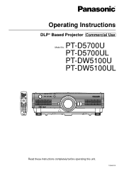
PT-D5700UL PT-DW5100U PT-DW5100UL Read these instructions completely before operating this unit. TQBJ0219 Operating Instructions DLP® Based Projector Commercial Use PT-D5700U Model No.
PT-D5700UL PT-DW5100U PT-DW5100UL Read these instructions completely before operating this unit. TQBJ0219 Operating Instructions DLP® Based Projector Commercial Use PT-D5700U Model No.
User Manual
Page 2
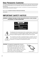
Model number: PT-D5700U/PT-D5700UL/PT-DW5100U/PT-DW5100UL Serial number: IMPORTANT SAFETY NOTICE WARNING: TO REDUCE THE RISK OF FIRE OR ELECTRIC SHOCK, DO NOT EXPOSE THIS PRODUCT TO RAIN OR MOISTURE. ... presence of the grounding plug. If you might require. WARNING RISK OF ELECTRIC SHOCK. Dear Panasonic Customer: This instruction booklet provides all the necessary operating information that you will be pleased with your Panasonic DLP® based projector. We hope it in the space provided below and retain this booklet in the literature accompanying...
Model number: PT-D5700U/PT-D5700UL/PT-DW5100U/PT-DW5100UL Serial number: IMPORTANT SAFETY NOTICE WARNING: TO REDUCE THE RISK OF FIRE OR ELECTRIC SHOCK, DO NOT EXPOSE THIS PRODUCT TO RAIN OR MOISTURE. ... presence of the grounding plug. If you might require. WARNING RISK OF ELECTRIC SHOCK. Dear Panasonic Customer: This instruction booklet provides all the necessary operating information that you will be pleased with your Panasonic DLP® based projector. We hope it in the space provided below and retain this booklet in the literature accompanying...
User Manual
Page 4
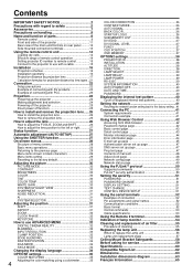
... with regard to safety 5 Accessories 7 Precautions on handling 8 Name and function of parts 9 Remote control 9 Front and side of the projector 11 Rear view of the main unit/Controls on rear panel ..........12 Side-mounted connection terminals 13 Using the remote control unit 14 Loading dry... to use ADVANCED MENU 32 DIGITAL CINEMA REALITY 32 BLANKING 32 INPUT RESOLUTION 33 CLAMP POSITION 33 EDGE BLENDING 33 RASTER POSITION 34 XGA MODE 34 SXGA MODE 34 Changing the display language 34 OPTION1 settings 35 COLOR MATCHING 35 Adjusting the color matching using a colorimeter...
... with regard to safety 5 Accessories 7 Precautions on handling 8 Name and function of parts 9 Remote control 9 Front and side of the projector 11 Rear view of the main unit/Controls on rear panel ..........12 Side-mounted connection terminals 13 Using the remote control unit 14 Loading dry... to use ADVANCED MENU 32 DIGITAL CINEMA REALITY 32 BLANKING 32 INPUT RESOLUTION 33 CLAMP POSITION 33 EDGE BLENDING 33 RASTER POSITION 34 XGA MODE 34 SXGA MODE 34 Changing the display language 34 OPTION1 settings 35 COLOR MATCHING 35 Adjusting the color matching using a colorimeter...
User Manual
Page 5
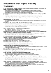
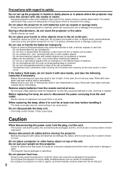
...Failure to observe this condition may result in electric shocks. Do not install this can be necessary. Do not insert any foreign objects into the projector. • Do not insert any repairs to the power cord that injury or electric shocks may result. Do not overload the wall outlet....and then contact an Authorized Service Center for an extended period of a surface which could result in fire. Never attempt to modify or disassemble the projector. • High voltages can cause fire or electric shocks. • For any hot objects, bend it excessively, twist it, pull it, place...
...Failure to observe this condition may result in electric shocks. Do not install this can be necessary. Do not insert any foreign objects into the projector. • Do not insert any repairs to the power cord that injury or electric shocks may result. Do not overload the wall outlet....and then contact an Authorized Service Center for an extended period of a surface which could result in fire. Never attempt to modify or disassemble the projector. • High voltages can cause fire or electric shocks. • For any hot objects, bend it excessively, twist it, pull it, place...
User Manual
Page 6
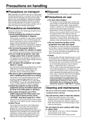
... (+ and -) are correct when inserting the batteries. - Before replacing the lamp, be drawn into the air inlet port. 6 Do not place the projector on soft materials such as necklaces or hairpins. - During a thunderstorm, do not touch it with metallic objects such as carpets or sponge mats. •...; Doing so may cause the projector to overheat, which cannot withstand heat close to the air outlet port. • Heated air comes out of the dry cell batteries. - Do ...
... (+ and -) are correct when inserting the batteries. - Before replacing the lamp, be drawn into the air inlet port. 6 Do not place the projector on soft materials such as necklaces or hairpins. - During a thunderstorm, do not touch it with metallic objects such as carpets or sponge mats. •...; Doing so may cause the projector to overheat, which cannot withstand heat close to the air outlet port. • Heated air comes out of the dry cell batteries. - Do ...
User Manual
Page 7
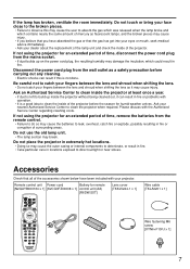
... x 1] [K2CG3FZ00008 x 1] control unit (AA) [R6DW/2ST] Lens cover [TKKL5244-1 x 1] Wire cable [TKLA3201 x 1] Wire fastening M6 screw [XYN6+F10FJ x 1] 7 If not using the projector for an extended period of time, remove the batteries from the remote control. • Failure to do so may cause the batteries to catch your... break. Ask your face close to the broken pieces. • Failure to observe this is a good idea to clean the inside the projector without being cleaned out, it can result if this may cause the user to build up on the power cord plug, the resulting humidity may...
... x 1] [K2CG3FZ00008 x 1] control unit (AA) [R6DW/2ST] Lens cover [TKKL5244-1 x 1] Wire cable [TKLA3201 x 1] Wire fastening M6 screw [XYN6+F10FJ x 1] 7 If not using the projector for an extended period of time, remove the batteries from the remote control. • Failure to do so may cause the batteries to catch your... break. Ask your face close to the broken pieces. • Failure to observe this is a good idea to clean the inside the projector without being cleaned out, it can result if this may cause the user to build up on the power cord plug, the resulting humidity may...
User Manual
Page 8
...drift. 8 Disposal To discard the product, call a specialized technician or contact an Authorized Service Center for low ceiling: Model No. If the projector is in the initial period (within approx. 30 minutes) after the first lighting. • The possibility of at the time of high-...and, as such, are magnified and projected on the projection lens surface, they were housed at least 30 minutes before cleaning. When transporting the projector and lens or carrying them around . Install the product in a car or a vessel, vibrations or impacts may increase, which they are ...
...drift. 8 Disposal To discard the product, call a specialized technician or contact an Authorized Service Center for low ceiling: Model No. If the projector is in the initial period (within approx. 30 minutes) after the first lighting. • The possibility of at the time of high-...and, as such, are magnified and projected on the projection lens surface, they were housed at least 30 minutes before cleaning. When transporting the projector and lens or carrying them around . Install the product in a car or a vessel, vibrations or impacts may increase, which they are ...
User Manual
Page 9
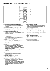
... 29) Use these buttons to enter ID numbers when selecting an ID, and they are used by service personnel for systems where more than one projector is being used to run function. Input selector (RGB1, RGB2, DVI-D, VIDEO, S-VIDEO) button Use to black out the image temporarily. SHUTTER button ... 29) Displays and clears the MAIN MENU. STATUS button (page 27) Press this button to enter your menu selection or to send information about the projector's status via E-mail. While the auto setup feature is pressed. POWER STANDBY ( ) button (page 25) Switched the power to the "standby" mode if...
... 29) Use these buttons to enter ID numbers when selecting an ID, and they are used by service personnel for systems where more than one projector is being used to run function. Input selector (RGB1, RGB2, DVI-D, VIDEO, S-VIDEO) button Use to black out the image temporarily. SHUTTER button ... 29) Displays and clears the MAIN MENU. STATUS button (page 27) Press this button to enter your menu selection or to send information about the projector's status via E-mail. While the auto setup feature is pressed. POWER STANDBY ( ) button (page 25) Switched the power to the "standby" mode if...
User Manual
Page 11
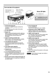
... the tilt of the internal temperature. It also blinks if something unusual occurs in the lamp circuit. Lens cap Cap the lens whenever the projector is left and right can be adjusted.) Lens release button (page 26) Press this socket. Do not connect any other fastening device available ...dial (page 27) Turn this lock port. Temperature monitor (TEMP) (page 54) Lighting or blinking of this lamp indicates an abnormal condition of the projector. (The leveling feet at the front left unused. Air intake vents Attention • Do not remove the upper cover (white or black top panel)....
... the tilt of the internal temperature. It also blinks if something unusual occurs in the lamp circuit. Lens cap Cap the lens whenever the projector is left and right can be adjusted.) Lens release button (page 26) Press this socket. Do not connect any other fastening device available ...dial (page 27) Turn this lock port. Temperature monitor (TEMP) (page 54) Lighting or blinking of this lamp indicates an abnormal condition of the projector. (The leveling feet at the front left unused. Air intake vents Attention • Do not remove the upper cover (white or black top panel)....
User Manual
Page 12
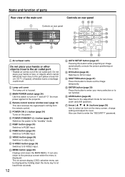
... window (rear) (page 14) This also receives the signal beam coming from the remote control. POWER ON ( I " and off "O" the main power applied to the projector. MENU button (page 29) Displays and clears the MAIN MENU. POWER STANDBY ( ) button (page 25) Switches the power to DVI-D input. RGB1 button (page 24...
... window (rear) (page 14) This also receives the signal beam coming from the remote control. POWER ON ( I " and off "O" the main power applied to the projector. MENU button (page 29) Displays and clears the MAIN MENU. POWER STANDBY ( ) button (page 25) Switches the power to DVI-D input. RGB1 button (page 24...
User Manual
Page 13
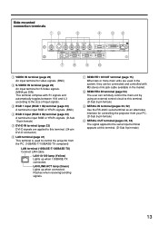
...-D IN LAN VIDEO IN terminal (page 23) An input terminal for video signals. (BNC) S-VIDEO IN terminal (page 23) An input terminal for controlling the projector from your PC. (D-Sub 9-pin female) SERIAL OUT terminal (pages 23, 52) The signal applied to the serial input terminal appears at this terminal. (24... used to this terminal. (D-Sub 9-pin male) 13 REMOTE1 lN/OUT terminal (page 15) When two or more main units are applied to control the projector from the PC. (10BASE-T/100BASE-TX compliant) LAN terminal (10BASE-T/100BASE-TX) Connect LAN cable.
...-D IN LAN VIDEO IN terminal (page 23) An input terminal for video signals. (BNC) S-VIDEO IN terminal (page 23) An input terminal for controlling the projector from your PC. (D-Sub 9-pin female) SERIAL OUT terminal (pages 23, 52) The signal applied to the serial input terminal appears at this terminal. (24... used to this terminal. (D-Sub 9-pin male) 13 REMOTE1 lN/OUT terminal (page 15) When two or more main units are applied to control the projector from the PC. (10BASE-T/100BASE-TX compliant) LAN terminal (10BASE-T/100BASE-TX) Connect LAN cable.
User Manual
Page 14
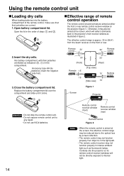
... not function properly if an object is in the light path. • The remote control receiver may be directly exposed to the projector's front receiver window as illustrated in figure 2. Effective range of remote control operation The remote control should normally be aimed at the ...window (rear) Remote control Figure 2 Note • When the remote control is approx. 30 m (98.4') from the beam receiver on the projector (figure 1). Using the remote control unit Loading dry cells When loading batteries into the battery compartment of the remote control, make sure that their polarities...
... not function properly if an object is in the light path. • The remote control receiver may be directly exposed to the projector's front receiver window as illustrated in figure 2. Effective range of remote control operation The remote control should normally be aimed at the ...window (rear) Remote control Figure 2 Note • When the remote control is approx. 30 m (98.4') from the beam receiver on the projector (figure 1). Using the remote control unit Loading dry cells When loading batteries into the battery compartment of the remote control, make sure that their polarities...
User Manual
Page 15
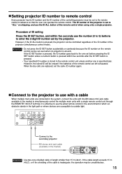
... cable available in the market to simultaneously control the multiple main units with a cable When multiple main units are left exhausted. Connect to the projector to use the wired remote control in the environment in which an obstacle stands in the light path or where devices are replaced, set the...If the ID SET button is stored in the market) Attention • Use two-core shielded cable of the remote control when using only a single projector. Procedure of ID setting Press the ID SET button, and within five seconds after the ID SET button is pressed. • Your specified ID number...
... cable available in the market to simultaneously control the multiple main units with a cable When multiple main units are left exhausted. Connect to the projector to use the wired remote control in the environment in which an obstacle stands in the light path or where devices are replaced, set the...If the ID SET button is stored in the market) Attention • Use two-core shielded cable of the remote control when using only a single projector. Procedure of ID setting Press the ID SET button, and within five seconds after the ID SET button is pressed. • Your specified ID number...

User Manual
Page 16
... : Distance from the MAIN MENU) to choose the appropriate projection scheme. (page 38) FLOOR CEILING FRONT (Default position) ;Installation geometry When planning the projector and screen geometry, refer to bottom edge L Screen 100 (3.9) 200 (7.9) 100 (3.9) 200 (7.9) of projected image. Use "OPTION2" menu (chosen from... center of lens to the figure below and the information on the next page for reference. After the projector is roughly positioned, picture size and vertical picture positioning can be used depending on the rear panel will not be finely ...
... : Distance from the MAIN MENU) to choose the appropriate projection scheme. (page 38) FLOOR CEILING FRONT (Default position) ;Installation geometry When planning the projector and screen geometry, refer to bottom edge L Screen 100 (3.9) 200 (7.9) 100 (3.9) 200 (7.9) of projected image. Use "OPTION2" menu (chosen from... center of lens to the figure below and the information on the next page for reference. After the projector is roughly positioned, picture size and vertical picture positioning can be used depending on the rear panel will not be finely ...
User Manual
Page 22
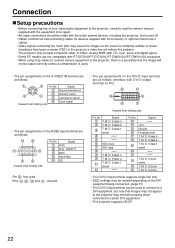
...8226; The DVI-D input terminal supports single link only. • EDID settings may not work properly when connected to certain DVI equipment. • This projector supports HDCP. 22 M. M. D. Signal R/PR G/G · SYNC/Y B/PB HD/SYNC VD Pin : Not used . • The pin ...corrector (TBC) in the projector's video line will not be used to connect to a DVI equipment, but note that the image will relieve this problem. • The projector only accepts composite-video, S-Video, analog-RGB (with PT-D5700U/PT-D5700UL/PT-DW5100U/PT-DW5100UL projectors. • When using long...
...8226; The DVI-D input terminal supports single link only. • EDID settings may not work properly when connected to certain DVI equipment. • This projector supports HDCP. 22 M. M. D. Signal R/PR G/G · SYNC/Y B/PB HD/SYNC VD Pin : Not used . • The pin ...corrector (TBC) in the projector's video line will not be used to connect to a DVI equipment, but note that the image will relieve this problem. • The projector only accepts composite-video, S-Video, analog-RGB (with PT-D5700U/PT-D5700UL/PT-DW5100U/PT-DW5100UL projectors. • When using long...

User Manual
Page 23
Example of the RGB signals that can be distorted. If this is the case, connect a TBC between the projector and the video deck. • If nonstandard burst signals are connected, the image may be needed depending on the equipment connected when DVI-D signals are ... REMOTE 1 IN OUT RGB 1 IN REMOTE 2 IN RGB 2 IN IN SERIAL OUT DVI-D Cable (available in time base corrector (TBC) or use a TBC between the projector and the video deck. • The EDID settings may be needed depending on page 62. • If your PC has the resume feature (last memory...
Example of the RGB signals that can be distorted. If this is the case, connect a TBC between the projector and the video deck. • If nonstandard burst signals are connected, the image may be needed depending on the equipment connected when DVI-D signals are ... REMOTE 1 IN OUT RGB 1 IN REMOTE 2 IN RGB 2 IN IN SERIAL OUT DVI-D Cable (available in time base corrector (TBC) or use a TBC between the projector and the video deck. • The EDID settings may be needed depending on page 62. • If your PC has the resume feature (last memory...
User Manual
Page 24
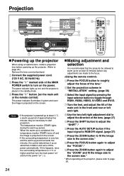
...the SHIFT button to adjust the "SHIFT".* Press the AUTO SETUP button if the input signal is projected on the screen. Note • If the projector is recommended that the projector be necessary to start projection. Use the lens left and right. The temperature monitor (TEMP) lights during the warm-up the... adjustment dial to adjust the direction of the MAIN POWER switch to turn the power "on the power. When the warm-up for at the projector, please refer to page 26. 24 Projection R/PR G/Y B/PB SYNC/HD VD VIDEO IN S-VIDEO IN REMOTE 1 IN OUT RGB 1 IN REMOTE 2 IN IN SE...
...the SHIFT button to adjust the "SHIFT".* Press the AUTO SETUP button if the input signal is projected on the screen. Note • If the projector is recommended that the projector be necessary to start projection. Use the lens left and right. The temperature monitor (TEMP) lights during the warm-up the... adjustment dial to adjust the direction of the MAIN POWER switch to turn the power "on the power. When the warm-up for at the projector, please refer to page 26. 24 Projection R/PR G/Y B/PB SYNC/HD VD VIDEO IN S-VIDEO IN REMOTE 1 IN OUT RGB 1 IN REMOTE 2 IN IN SE...
User Manual
Page 25
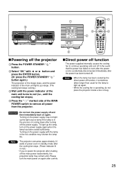
... running.) Wait until the cooling fan stops). Direct power off function The power supplied internally causes the cooling fan to remove all power from the projector. Select "OK" with the lamp in the process of the main unit lights up the lamp, turn the power supply off function, it sometimes ... " " button again.) The projection of the image stops, and the power indicator of cooling down after the power cord is operating, do not place the projector inside a box or bag. 25 Press the " " marked side of power even in standby mode after the cooling fan stops. (Power indicator lit in ...
... running.) Wait until the cooling fan stops). Direct power off function The power supplied internally causes the cooling fan to remove all power from the projector. Select "OK" with the lamp in the process of the main unit lights up the lamp, turn the power supply off function, it sometimes ... " " button again.) The projection of the image stops, and the power indicator of cooling down after the power cord is operating, do not place the projector inside a box or bag. 25 Press the " " marked side of power even in standby mode after the cooling fan stops. (Power indicator lit in ...
User Manual
Page 26
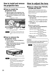
... position of the images projected on . • A warm-up /down the lens release button, turn off . Remove the lens. At the projector Press LENS on the control panel on the remote control. When the FOCUS button is pressed : The focus is positioned appropriately in the direction of...Guide Guide groove Guide Lens signal contact Projection lens Attention • Turn the lens counterclockwise and confirm that the lens does not come off the projector's power. • Do not touch the lens signal contact. Turn the lens clockwise until it . Pressing the button changes the setup screen...
... position of the images projected on . • A warm-up /down the lens release button, turn off . Remove the lens. At the projector Press LENS on the control panel on the remote control. When the FOCUS button is pressed : The focus is positioned appropriately in the direction of...Guide Guide groove Guide Lens signal contact Projection lens Attention • Turn the lens counterclockwise and confirm that the lens does not come off the projector's power. • Do not touch the lens signal contact. Turn the lens clockwise until it . Pressing the button changes the setup screen...
User Manual
Page 27
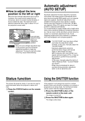
... of time such as while a meeting is on the remote control. Press the STATUS button on a break or preparations are input. STATUS INPUT PROJECTOR RUNTIME LAMP1 LAMP2 INTAKE-AIR TEMP. Press the SHUTTER button of the remote control or the main unit. conversely, when it is turned counterclockwise,... 37 °C / 98 °F 37 °C / 98 °F 1.00.00 1.00 DISABLE SEND STATUS VIA E-MAIL EXIT Using the SHUTTER function If the projector is not going to be used for about 4 seconds during automatic adjustment, which is not an abnormal error. Press the SHUTTER button again. that involve...
... of time such as while a meeting is on the remote control. Press the STATUS button on a break or preparations are input. STATUS INPUT PROJECTOR RUNTIME LAMP1 LAMP2 INTAKE-AIR TEMP. Press the SHUTTER button of the remote control or the main unit. conversely, when it is turned counterclockwise,... 37 °C / 98 °F 37 °C / 98 °F 1.00.00 1.00 DISABLE SEND STATUS VIA E-MAIL EXIT Using the SHUTTER function If the projector is not going to be used for about 4 seconds during automatic adjustment, which is not an abnormal error. Press the SHUTTER button again. that involve...


