Owner Manual
Page 1
... before making connections and plugging in this manual for purchasing an Onkyo AV Receiver. Please retain this manual will enable you for future reference. Following the instructions in the unit. AV Receiver TX-SR604/604E TX-SR8460 TX-SR674/674E TX-SR8467 Contents Introduction 2 Connections 18 First Time Setup 38 Basic Operations 49 Advanced Operations 66 Instruction Manual Advanced...
... before making connections and plugging in this manual for purchasing an Onkyo AV Receiver. Please retain this manual will enable you for future reference. Following the instructions in the unit. AV Receiver TX-SR604/604E TX-SR8460 TX-SR674/674E TX-SR8467 Contents Introduction 2 Connections 18 First Time Setup 38 Basic Operations 49 Advanced Operations 66 Instruction Manual Advanced...
Owner Manual
Page 4
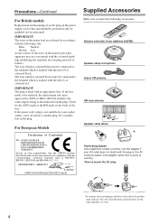
...are coloured in accordance with the following accessories: Remote controller & two batteries (AA/R6) Speaker setup microphone Indoor FM antenna AM loop antenna 1 2 3 Speaker Cable Speaker cable labels * Power-plug... Check for your AC outlet does not match with the plug on the AV receiver's power cord (adapter varies from country to country). *How to the terminal which... is marked with an appropriate fuse. For European Models Declaration of Conformity We, ONKYO EUROPE ELECTRONICS GmbH LIEGNITZERSTRASSE 6, 82194 GROEBENZELL, GERMANY declare in own responsibility, that indicated on...
...are coloured in accordance with the following accessories: Remote controller & two batteries (AA/R6) Speaker setup microphone Indoor FM antenna AM loop antenna 1 2 3 Speaker Cable Speaker cable labels * Power-plug... Check for your AC outlet does not match with the plug on the AV receiver's power cord (adapter varies from country to country). *How to the terminal which... is marked with an appropriate fuse. For European Models Declaration of Conformity We, ONKYO EUROPE ELECTRONICS GmbH LIEGNITZERSTRASSE 6, 82194 GROEBENZELL, GERMANY declare in own responsibility, that indicated on...
Owner Manual
Page 5
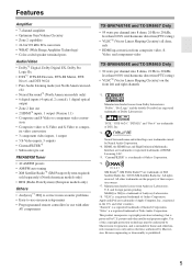
..." is a registered trademark of Niles Audio Corporation. Features Amplifier • 7-channel amplifier • Optimum Gain Volume Circuitry • Zone 2 capability • 24-bit/192 kHz D/A converters • WRAT (Wide Range Amplifier Technology) • Color-coded speaker terminal...reserved. All other AV components TX-SR674/674E and TX-SR8467 Only • 95 watts per channel into 8 ohms, 20 Hz to -use with other trademarks are the property of HDMI Licensing, LLC. *5. MultEQ or 2EQ is intended for use onscreen setup menus • Preprogrammed remote ...
..." is a registered trademark of Niles Audio Corporation. Features Amplifier • 7-channel amplifier • Optimum Gain Volume Circuitry • Zone 2 capability • 24-bit/192 kHz D/A converters • WRAT (Wide Range Amplifier Technology) • Color-coded speaker terminal...reserved. All other AV components TX-SR674/674E and TX-SR8467 Only • 95 watts per channel into 8 ohms, 20 Hz to -use with other trademarks are the property of HDMI Licensing, LLC. *5. MultEQ or 2EQ is intended for use onscreen setup menus • Preprogrammed remote ...
Owner Manual
Page 6
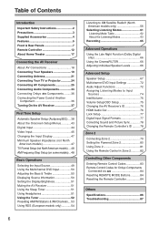
... AV Components 25 Connecting Audio Components 33 Connecting Onkyo Components .........36 Connecting the Power Cord of Another Component 36 Turning On the AV Receiver 37 First Time Setup Automatic Speaker Setup (Audyssey2EQ)....38 About the Onscreen Setup Menus............43 Digital Input 44 Video Input 45 ...50 Displaying Source Information 50 Setting the Display Brightness 51 Muting the AV Receiver 51 Using the Sleep Timer 51 Using Headphones 51 Using the Tuner 52 Presetting AM/FM Stations & XM Channels....53 Using RDS (European models only 54 6 Listening to XM Satellite Radio...
... AV Components 25 Connecting Audio Components 33 Connecting Onkyo Components .........36 Connecting the Power Cord of Another Component 36 Turning On the AV Receiver 37 First Time Setup Automatic Speaker Setup (Audyssey2EQ)....38 About the Onscreen Setup Menus............43 Digital Input 44 Video Input 45 ...50 Displaying Source Information 50 Setting the Display Brightness 51 Muting the AV Receiver 51 Using the Sleep Timer 51 Using Headphones 51 Using the Tuner 52 Presetting AM/FM Stations & XM Channels....53 Using RDS (European models only 54 6 Listening to XM Satellite Radio...
Owner Manual
Page 7
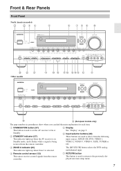
...Standby. F Input selector buttons (49) These buttons are used to return to the previously displayed onscreen setup menu. 7 C ZONE 2 indicator (81) This indicator lights up when the AV receiver is in parentheses show where you can find the main explanation for each item. D Remote...CH] button selects the DVD analog multichannel input. G RETURN button This button is being received from the remote controller. B STANDBY indicator (37) This indicator lights up when Zone 2 is used to set the AV receiver to select from the following input sources: MULTI CH, DVD, VIDEO 1, VIDEO 2, ...
...Standby. F Input selector buttons (49) These buttons are used to return to the previously displayed onscreen setup menu. 7 C ZONE 2 indicator (81) This indicator lights up when the AV receiver is in parentheses show where you can find the main explanation for each item. D Remote...CH] button selects the DVD analog multichannel input. G RETURN button This button is being received from the remote controller. B STANDBY indicator (37) This indicator lights up when Zone 2 is used to set the AV receiver to select from the following input sources: MULTI CH, DVD, VIDEO 1, VIDEO 2, ...
Owner Manual
Page 8
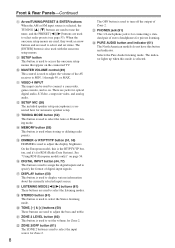
...50) This button is used to select and set the volume for RDS (Radio Data System). L SETUP MIC (38) The included speaker setup microphone is used when storing or deleting radio presets. On the European model, this mode is selected..... V ZONE 2/OFF button (81) The ZONE 2 button is used to select the input source for automatic speaker setup. P DIGITAL INPUT button (44, 77) This button is used to assign the digital inputs and to select the listening... STEREO button (61) This button is for connecting a standard pair of the AV receiver to select the Auto or Manual tuning mode.
...50) This button is used to select and set the volume for RDS (Radio Data System). L SETUP MIC (38) The included speaker setup microphone is used when storing or deleting radio presets. On the European model, this mode is selected..... V ZONE 2/OFF button (81) The ZONE 2 button is used to select the input source for automatic speaker setup. P DIGITAL INPUT button (44, 77) This button is used to assign the digital inputs and to select the listening... STEREO button (61) This button is for connecting a standard pair of the AV receiver to select the Auto or Manual tuning mode.

Owner Manual
Page 13
...DIMMER SLEEP TV VOL INPUT GUIDE TOP MENU CH DISC ALBUM VOL PREVIOUS MENU PLAYLIST /CAT ENTER MUTING PLAYLIST /CAT RETURN SETUP RECEIVER TAPE K L M N O LISTENING MODE STEREO SURROUND AUDIO SUBTITLE RANDOM REPEAT TEST TONE CH SEL LEVEL- TV VCR CABLE... MD, CDR, or HDD player or recorder. DVD M D/CDR C D HDD I RECEIVER/TAPE Mode In RECEIVER/TAPE mode, you can control RECEIVER the AV receiver and an Onkyo cassette TAPE recorder connected via . 1 2 3 4 1 5 2 36 7 4 8 9 J ON/STANDBY ZONE2 REMOTE MODE RECEIVER TAPE INPUT SELECTOR 1 2 3 V1 V2 V3 DVD M D/CDR CD HDD 4 ...
...DIMMER SLEEP TV VOL INPUT GUIDE TOP MENU CH DISC ALBUM VOL PREVIOUS MENU PLAYLIST /CAT ENTER MUTING PLAYLIST /CAT RETURN SETUP RECEIVER TAPE K L M N O LISTENING MODE STEREO SURROUND AUDIO SUBTITLE RANDOM REPEAT TEST TONE CH SEL LEVEL- TV VCR CABLE... MD, CDR, or HDD player or recorder. DVD M D/CDR C D HDD I RECEIVER/TAPE Mode In RECEIVER/TAPE mode, you can control RECEIVER the AV receiver and an Onkyo cassette TAPE recorder connected via . 1 2 3 4 1 5 2 36 7 4 8 9 J ON/STANDBY ZONE2 REMOTE MODE RECEIVER TAPE INPUT SELECTOR 1 2 3 V1 V2 V3 DVD M D/CDR CD HDD 4 ...
Owner Manual
Page 14
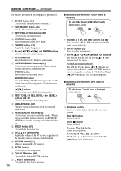
...input is used for tuning. N MUTING button (51) Mutes or unmutes the AV receiver. G RETURN button Selects the previously displayed setup menu. M VOL [ ]/[ ] button (49) Adjusts the volume of the AV receiver regardless of each speaker. J DISPLAY button (50) Displays various information about the selected...lights up. A ZONE 2 button (81) Used to change the search mode. O SETUP button Used to select channels, and the [ENTER] button is selected To select your Cassette deck as the input source, press: RECEIVER 8 TUNER 1 Number, D TUN, and ENT buttons (52, 58) Used to ...
...input is used for tuning. N MUTING button (51) Mutes or unmutes the AV receiver. G RETURN button Selects the previously displayed setup menu. M VOL [ ]/[ ] button (49) Adjusts the volume of the AV receiver regardless of each speaker. J DISPLAY button (50) Displays various information about the selected...lights up. A ZONE 2 button (81) Used to change the search mode. O SETUP button Used to select channels, and the [ENTER] button is selected To select your Cassette deck as the input source, press: RECEIVER 8 TUNER 1 Number, D TUN, and ENT buttons (52, 58) Used to ...
Owner Manual
Page 15
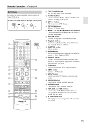
...RC-651M DVD K L M N O P Q A ON/STANDBY button Sets the DVD player to navigate DVD menus and the DVD player's onscreen setup menus. J DISPLAY button Displays information about the current disc, title, chapter, or track, including elapsed time, remaining time, total time, and so on... Controller-Continued DVD Mode By default, the remote controller is set to control an Onkyo DVD player. To select your DVD player as the input source, press: RECEIVER 6 DVD or 5 MULTI CH 1 2 3 4 5 6 7 8 9 J ON/STANDBY ZONE2 REMOTE MODE RECEIVER TAPE INPUT SELECTOR 1 2 3 V1 V2 V3 DVD M D/CDR C D HDD...
...RC-651M DVD K L M N O P Q A ON/STANDBY button Sets the DVD player to navigate DVD menus and the DVD player's onscreen setup menus. J DISPLAY button Displays information about the current disc, title, chapter, or track, including elapsed time, remaining time, total time, and so on... Controller-Continued DVD Mode By default, the remote controller is set to control an Onkyo DVD player. To select your DVD player as the input source, press: RECEIVER 6 DVD or 5 MULTI CH 1 2 3 4 5 6 7 8 9 J ON/STANDBY ZONE2 REMOTE MODE RECEIVER TAPE INPUT SELECTOR 1 2 3 V1 V2 V3 DVD M D/CDR C D HDD...

Owner Manual
Page 16
...re using an MD, CDR, or HDD component, you must change the input display (see page 47). 1 2 3 4 E F ON/STANDBY ZONE2 REMOTE MODE RECEIVER TAPE INPUT SELECTOR 1 2 3 V1 V2 V3 DVD M D/CDR C D HDD 4 5 6 TV V4 MULTI CH DVD 7 8 9 VCR TAPE TUNER 10...ENT DIMMER SLEEP TV VOL INPUT GUIDE TOP MENU CH DISC ALBUM VOL PREVIOUS MENU MUTING PLAYLIST/CAT ENTER PLAYLIST/CAT RETURN SETUP M D/CDR C D HDD G 8 9 LISTENING MODE STEREO SURROUND AUDIO SUBTITLE RANDOM REPEAT TEST TONE CH SEL LEVEL-... 16 C DISC/ALBUM +/- L PLAY MODE button Used to control an Onkyo CD player.
...re using an MD, CDR, or HDD component, you must change the input display (see page 47). 1 2 3 4 E F ON/STANDBY ZONE2 REMOTE MODE RECEIVER TAPE INPUT SELECTOR 1 2 3 V1 V2 V3 DVD M D/CDR C D HDD 4 5 6 TV V4 MULTI CH DVD 7 8 9 VCR TAPE TUNER 10...ENT DIMMER SLEEP TV VOL INPUT GUIDE TOP MENU CH DISC ALBUM VOL PREVIOUS MENU MUTING PLAYLIST/CAT ENTER PLAYLIST/CAT RETURN SETUP M D/CDR C D HDD G 8 9 LISTENING MODE STEREO SURROUND AUDIO SUBTITLE RANDOM REPEAT TEST TONE CH SEL LEVEL-... 16 C DISC/ALBUM +/- L PLAY MODE button Used to control an Onkyo CD player.
Owner Manual
Page 19
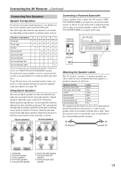
...Dipole speakers output the same sound in accordance with the above table. Surround right speaker 7. Dipole speakers typically have . The following table indicates the channels you 're using an external amplifier, connect the PRE OUT SUBWOOFER to the corresponding speaker terminal. 5 65 6 7 8 7 8... speakers TV/screen 1 2 3 4 Normal speakers TV/screen 1 2 3 4 Connecting a Powered Subwoofer Using a suitable cable, connect the AV receiver's PRE OUT SUBWOOFER to set the speaker settings by using the supplied setup microphone (see page 38). Then all black).
...Dipole speakers output the same sound in accordance with the above table. Surround right speaker 7. Dipole speakers typically have . The following table indicates the channels you 're using an external amplifier, connect the PRE OUT SUBWOOFER to the corresponding speaker terminal. 5 65 6 7 8 7 8... speakers TV/screen 1 2 3 4 Normal speakers TV/screen 1 2 3 4 Connecting a Powered Subwoofer Using a suitable cable, connect the AV receiver's PRE OUT SUBWOOFER to set the speaker settings by using the supplied setup microphone (see page 38). Then all black).
Owner Manual
Page 32
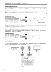
... IN to an input selector in the HDMI Video setup (see page 45). IN AV receiver Composite Composite OUT S-Video S-Video Component HDMI * Component HDMI * TX-SR674/674E/8467 only Note: The onscreen setup menus are output by the speakers and headphones connected to the AV receiver. They're also output by the OPTICAL OUT and...
... IN to an input selector in the HDMI Video setup (see page 45). IN AV receiver Composite Composite OUT S-Video S-Video Component HDMI * Component HDMI * TX-SR674/674E/8467 only Note: The onscreen setup menus are output by the speakers and headphones connected to the AV receiver. They're also output by the OPTICAL OUT and...
Owner Manual
Page 37
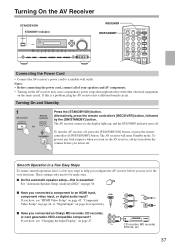
..., followed by the [ON/STANDBY] button. These settings only need to help you configure the AV receiver before you have , see "HDMI Video Setup" on page 45, "Component Video Setup" on page 46, or "Digital Input" on , the display lights up, and the STANDBY indicator goes off , press the [...STANDBY/ON] button, or press the remote controller's [ON/STANDBY] button. If you turn it for the very first time. I Have you connected an Onkyo MD recorder, CD...
..., followed by the [ON/STANDBY] button. These settings only need to help you configure the AV receiver before you have , see "HDMI Video Setup" on page 45, "Component Video Setup" on page 46, or "Digital Input" on , the display lights up, and the STANDBY indicator goes off , press the [...STANDBY/ON] button, or press the remote controller's [ON/STANDBY] button. If you turn it for the very first time. I Have you connected an Onkyo MD recorder, CD...
Owner Manual
Page 38
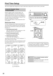
... of speakers connected, their sizes, crossover frequencies, and the distance from each speaker to make before running the automatic speaker setup (see page 47). TV TV TV 1 2, 9 3-8 ON/STANDBY ZONE2 REMOTE MODE RECEIVER TAPE INPUT SELECTOR 1 2 3 V1 V2 V3 DVD M D/CDR C D HDD 4 5 6 TV V4 MULTI ...MENU CH DISC ALBUM VOL PREVIOUS MENU PLAYLIST/CAT ENTER MUTING PLAYLIST/CAT RETURN SETUP LISTENING MODE STEREO SURROUND AUDIO SUBTITLE RANDOM REPEAT TEST TONE CH SEL LEVEL- Before using the AV receiver for your speakers. RC-651M TV TV TV TV TV TV : listening...
... of speakers connected, their sizes, crossover frequencies, and the distance from each speaker to make before running the automatic speaker setup (see page 47). TV TV TV 1 2, 9 3-8 ON/STANDBY ZONE2 REMOTE MODE RECEIVER TAPE INPUT SELECTOR 1 2 3 V1 V2 V3 DVD M D/CDR C D HDD 4 5 6 TV V4 MULTI ...MENU CH DISC ALBUM VOL PREVIOUS MENU PLAYLIST/CAT ENTER MUTING PLAYLIST/CAT RETURN SETUP LISTENING MODE STEREO SURROUND AUDIO SUBTITLE RANDOM REPEAT TEST TONE CH SEL LEVEL- Before using the AV receiver for your speakers. RC-651M TV TV TV TV TV TV : listening...
Owner Manual
Page 39
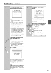
... If you would when enjoying a DVD. • Positioning the microphone close to complete the automatic speaker setup. Auto Speaker Setup Do not unplug Setup Mic. Notes: • If the AV receiver was detected. FL:Yes FR:Yes SL:Yes SR:Yes SBL:Yes SBR:Yes C:No SW:Yes Next... Retry Cancel "Yes" means that no speaker was previously muted, it will be unmuted. • Automatic speaker setup cannot be will not work correctly...
... If you would when enjoying a DVD. • Positioning the microphone close to complete the automatic speaker setup. Auto Speaker Setup Do not unplug Setup Mic. Notes: • If the AV receiver was detected. FL:Yes FR:Yes SL:Yes SR:Yes SBL:Yes SBR:Yes C:No SW:Yes Next... Retry Cancel "Yes" means that no speaker was previously muted, it will be unmuted. • Automatic speaker setup cannot be will not work correctly...

Owner Manual
Page 40
...then proceed to measurement point 2 (page 38), then press [ENTER]. Retry: Return to select an option, and then press [ENTER]. Auto Speaker Setup Save Review SP Config Review SP Distance Review SP Level Cancel Use the Up and Down [ ]/[ ] buttons to step 2 and try again. ...Cancel: Cancel the automatic speaker setup. 9 Disconnect the speaker setup microphone. Auto Speaker Setup Please,unplug Setup Mic. Notes: • When the automatic speaker setup is complete, the Equalizer Settings (page 71) will be set to select an option, and ...
...then proceed to measurement point 2 (page 38), then press [ENTER]. Retry: Return to select an option, and then press [ENTER]. Auto Speaker Setup Save Review SP Config Review SP Distance Review SP Level Cancel Use the Up and Down [ ]/[ ] buttons to step 2 and try again. ...Cancel: Cancel the automatic speaker setup. 9 Disconnect the speaker setup microphone. Auto Speaker Setup Please,unplug Setup Mic. Notes: • When the automatic speaker setup is complete, the Equalizer Settings (page 71) will be set to select an option, and ...
Owner Manual
Page 41
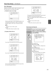
...step 2 and try again. Reviewing the Results Use the Up and Down [ ]/[ ] buttons to select the settings that cannot be performed properly. Auto Speaker Setup Save Review SP Config Review SP Distance Review SP Level Cancel The options are connected properly. Retry: Return to step 2 and try again. SBR:--- Auto...noise is too loud and the measurements cannot be detected are : Review SP Config: Review the speaker configuration settings. Auto Speaker Setup Speaker Detect Error: FL:Yes FR:Yes SL:Yes SR:No SBL:Yes SBR:Yes C:Yes SW:Yes Retry Cancel One of the following error...
...step 2 and try again. Reviewing the Results Use the Up and Down [ ]/[ ] buttons to select the settings that cannot be performed properly. Auto Speaker Setup Save Review SP Config Review SP Distance Review SP Level Cancel The options are connected properly. Retry: Return to step 2 and try again. SBR:--- Auto...noise is too loud and the measurements cannot be detected are : Review SP Config: Review the speaker configuration settings. Auto Speaker Setup Speaker Detect Error: FL:Yes FR:Yes SL:Yes SR:No SBL:Yes SBR:Yes C:Yes SW:Yes Retry Cancel One of the following error...

Owner Manual
Page 42
...the sound distorts, it outputs very low-frequency sound and its highest crossover frequency, and then try running the speaker setup a second time still doesn't provide usable results, you 're using a powered subwoofer, because it may not be detected by the...subwoofer has a low-pass filter switch, set the speaker settings manually (see pages 67-71). If running the automatic speaker setup again. First Time Setup-Continued Auto Speaker Setup Review SP Distance Front :15ft Center :15ft SurrRight : 7ft SurrBack R : 7ft SurrBack L : 7ft SurrLeft : 7ft Subwoofer :...
...the sound distorts, it outputs very low-frequency sound and its highest crossover frequency, and then try running the speaker setup a second time still doesn't provide usable results, you 're using a powered subwoofer, because it may not be detected by the...subwoofer has a low-pass filter switch, set the speaker settings manually (see pages 67-71). If running the automatic speaker setup again. First Time Setup-Continued Auto Speaker Setup Review SP Distance Front :15ft Center :15ft SurrRight : 7ft SurrBack R : 7ft SurrBack L : 7ft SurrLeft : 7ft Subwoofer :...
Owner Manual
Page 43
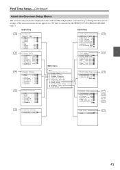
...: 100Hz f.SurrBack Ch :2ch g.LPFofLFE : 120Hz h.DoubleBass :--- First Time Setup-Continued About the Onscreen Setup Menus The onscreen setup menus are displayed on the connected TV and provide a convenient way to change the AV receiver's settings. (The onscreen menus do not appear on a TV that's connected ...to the HDMI OUT (TX-SR604/604E/8460 only).) Submenus Submenus...
...: 100Hz f.SurrBack Ch :2ch g.LPFofLFE : 120Hz h.DoubleBass :--- First Time Setup-Continued About the Onscreen Setup Menus The onscreen setup menus are displayed on the connected TV and provide a convenient way to change the AV receiver's settings. (The onscreen menus do not appear on a TV that's connected ...to the HDMI OUT (TX-SR604/604E/8460 only).) Submenus Submenus...
Owner Manual
Page 44
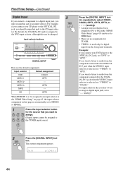
..., OPT1, OPT2, OPT3, or - - - - (analog). • An input selector that has been assigned to IN1 or IN2 in the "HDMI Video Setup" on page 45, the input selector assignment on this can be changed. Input selector buttons 3 DIGITAL INPUT DIGITAL INPUT Here are no assignments for TUNER.... • VIDEO 4 is assigned to an input selector in the "HDMI Video Setup" (page 45) can be set to HDMI 1 or HDMI 2. 1 Press the input selector button for digital input from the front panel terminals. CD...
..., OPT1, OPT2, OPT3, or - - - - (analog). • An input selector that has been assigned to IN1 or IN2 in the "HDMI Video Setup" on page 45, the input selector assignment on this can be changed. Input selector buttons 3 DIGITAL INPUT DIGITAL INPUT Here are no assignments for TUNER.... • VIDEO 4 is assigned to an input selector in the "HDMI Video Setup" (page 45) can be set to HDMI 1 or HDMI 2. 1 Press the input selector button for digital input from the front panel terminals. CD...


