Owner Manual
Page 1
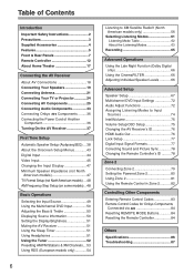
... unit. Please read this manual will enable you for future reference. Controlling Other Components ....83 Specifications 86 Troubleshooting 87 En AV Receiver TX-SR604/604E TX-SR8460 TX-SR674/674E TX-SR8467 Contents Introduction 2 Connections 18 First Time Setup 38 Basic Operations 49 Advanced Operations 66 Instruction Manual Advanced Setup 67 Zone 2 79 Thank...
... unit. Please read this manual will enable you for future reference. Controlling Other Components ....83 Specifications 86 Troubleshooting 87 En AV Receiver TX-SR604/604E TX-SR8460 TX-SR674/674E TX-SR8467 Contents Introduction 2 Connections 18 First Time Setup 38 Basic Operations 49 Advanced Operations 66 Instruction Manual Advanced Setup 67 Zone 2 79 Thank...
Owner Manual
Page 3
... from the AC power source. However, there is no guarantee that the plug is not userserviceable. Recording Copyright-Unless it checked by your Onkyo dealer. 6. AC Fuse-The AC fuse inside this unit or its power cord while your area meets the voltage requirements printed on the unit...instructions, may damage the finish or remove the panel lettering. 4. Before you do not intend to radio or television reception, which the receiver is set to comply with Wet Hands-Never handle this unit, have a voltage selector switch for an extended period, remove the power cord from...
... from the AC power source. However, there is no guarantee that the plug is not userserviceable. Recording Copyright-Unless it checked by your Onkyo dealer. 6. AC Fuse-The AC fuse inside this unit or its power cord while your area meets the voltage requirements printed on the unit...instructions, may damage the finish or remove the panel lettering. 4. Before you do not intend to radio or television reception, which the receiver is set to comply with Wet Hands-Never handle this unit, have a voltage selector switch for an extended period, remove the power cord from...
Owner Manual
Page 4
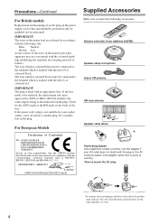
... plug is not suitable for the ASTA mark or the BSI mark on the body of the fuse. For European Models Declaration of Conformity We, ONKYO EUROPE ELECTRONICS GmbH LIEGNITZERSTRASSE 6, 82194 GROEBENZELL, GERMANY declare in compliance with an appropriate fuse. IMPORTANT The plug is fitted with the corresponding technical... AC plug on the power supply cord of this unit should be connected to the terminal which is marked with the plug on the AV receiver's power cord (adapter varies from country to country). *How to mount the AC plug: * In catalogs and on packaging, the letter at the ...
... plug is not suitable for the ASTA mark or the BSI mark on the body of the fuse. For European Models Declaration of Conformity We, ONKYO EUROPE ELECTRONICS GmbH LIEGNITZERSTRASSE 6, 82194 GROEBENZELL, GERMANY declare in compliance with an appropriate fuse. IMPORTANT The plug is fitted with the corresponding technical... AC plug on the power supply cord of this unit should be connected to the terminal which is marked with the plug on the AV receiver's power cord (adapter varies from country to country). *How to mount the AC plug: * In catalogs and on packaging, the letter at the ...
Owner Manual
Page 6
... Your TV or Projector 24 Connecting AV Components 25 Connecting Audio Components 33 Connecting Onkyo Components .........36 Connecting the Power Cord of Another Component 36 Turning On the AV Receiver 37 First Time Setup Automatic Speaker Setup (Audyssey2EQ)....38 About the Onscreen Setup Menus...Treble 50 Displaying Source Information 50 Setting the Display Brightness 51 Muting the AV Receiver 51 Using the Sleep Timer 51 Using Headphones 51 Using the Tuner 52 Presetting AM/FM Stations & XM Channels....53 Using RDS (European models only 54 6 Listening to XM Satellite Radio&#...
... Your TV or Projector 24 Connecting AV Components 25 Connecting Audio Components 33 Connecting Onkyo Components .........36 Connecting the Power Cord of Another Component 36 Turning On the AV Receiver 37 First Time Setup Automatic Speaker Setup (Audyssey2EQ)....38 About the Onscreen Setup Menus...Treble 50 Displaying Source Information 50 Setting the Display Brightness 51 Muting the AV Receiver 51 Using the Sleep Timer 51 Using Headphones 51 Using the Tuner 52 Presetting AM/FM Stations & XM Channels....53 Using RDS (European models only 54 6 Listening to XM Satellite Radio&#...
Owner Manual
Page 7
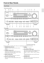
...CH, DVD, VIDEO 1, VIDEO 2, VIDEO 3, VIDEO 4, TAPE, TUNER or CD. E Display See "Display" on page 9. D Remote control sensor (12) This sensor receives control signals from the remote controller. The [MULTI CH] button selects the DVD analog multichannel input. G RETURN button This button is being...This button is selected. F Input selector buttons (49) These buttons are used to set the AV receiver to On or Standby. C ZONE 2 indicator (81) This indicator lights up when the AV receiver is in parentheses show where you can find the main explanation for each item. Front & ...
...CH, DVD, VIDEO 1, VIDEO 2, VIDEO 3, VIDEO 4, TAPE, TUNER or CD. E Display See "Display" on page 9. D Remote control sensor (12) This sensor receives control signals from the remote controller. The [MULTI CH] button selects the DVD analog multichannel input. G RETURN button This button is being...This button is selected. F Input selector buttons (49) These buttons are used to set the AV receiver to On or Standby. C ZONE 2 indicator (81) This indicator lights up when the AV receiver is in parentheses show where you can find the main explanation for each item. Front & ...
Owner Manual
Page 8
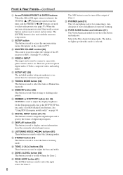
... North American models do not have this mode is selected. J MASTER VOLUME control (49) This control is used to adjust the volume of the AV receiver to turn off the output of Zone 2. M TUNING MODE button (52) This button is used to adjust the display brightness. O DIMMER or RT/PTY/TP...
... North American models do not have this mode is selected. J MASTER VOLUME control (49) This control is used to adjust the volume of the AV receiver to turn off the output of Zone 2. M TUNING MODE button (52) This button is used to adjust the display brightness. O DIMMER or RT/PTY/TP...
Owner Manual
Page 9
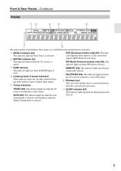
...selected listening mode and the format of the display shows various information about the currently selected source. This indicator flashes while the AV receiver is selected. 2 MUTING indicator (51) RDS (European models only) (54): This indicator lights up when tuned to a stereo FM station... signals. 5 Tuning indicators MEMORY (53): This indicator lights up when presetting radio stations. TUNED (52): This indicator lights up when the AV receiver is used. 4 Listening mode & format indicators These indicators show where you can find the main explanation for each item. 1 ZONE 2...
...selected listening mode and the format of the display shows various information about the currently selected source. This indicator flashes while the AV receiver is selected. 2 MUTING indicator (51) RDS (European models only) (54): This indicator lights up when tuned to a stereo FM station... signals. 5 Tuning indicators MEMORY (53): This indicator lights up when presetting radio stations. TUNED (52): This indicator lights up when the AV receiver is used. 4 Listening mode & format indicators These indicators show where you can find the main explanation for each item. 1 ZONE 2...
Owner Manual
Page 10
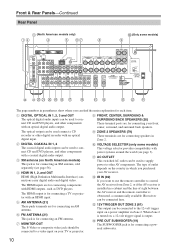
... for connecting an AM antenna. G MONITOR OUT The S-Video or composite video jack should be connected to control the AV receiver from Zone 2, or if the AV receiver is installed in a cabinet and the line of outlet depends on a power amplifier in which you can be ... (only some models) 9 VOLTAGE SELECTOR 120V 220-240V N M VU T S R Q P ON ML K The page numbers in Zone 2. The type of sight between the AV receiver and the remote controller is for connecting a TV or projector with HDMI outputs, such as DVD players. B DIGITAL COAXIAL IN 1, 2 The coaxial digital audio inputs...
... for connecting an AM antenna. G MONITOR OUT The S-Video or composite video jack should be connected to control the AV receiver from Zone 2, or if the AV receiver is installed in a cabinet and the line of outlet depends on a power amplifier in which you can be ... (only some models) 9 VOLTAGE SELECTOR 120V 220-240V N M VU T S R Q P ON ML K The page numbers in Zone 2. The type of sight between the AV receiver and the remote controller is for connecting a TV or projector with HDMI outputs, such as DVD players. B DIGITAL COAXIAL IN 1, 2 The coaxial digital audio inputs...
Owner Manual
Page 11
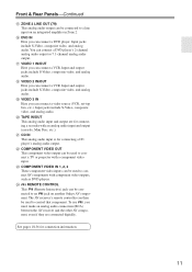
...for connection information. 11 See pages 18-36 for connecting a CD player's analog audio output. The AV receiver's remote controller can then be used to connect AV components with an analog audio input and output (cassette... video inputs can be used to a line input on another Onkyo AV component. P DVD IN Here you must make an analog audio connection (RCA) between the AV receiver and the other AV component, even if they are for connecting... you can connect a VCR. S VIDEO 3 IN Here you can connect a DVD player's 2-channel analog audio output or 7.1-channel analog audio output.
...for connection information. 11 See pages 18-36 for connecting a CD player's analog audio output. The AV receiver's remote controller can then be used to connect AV components with an analog audio input and output (cassette... video inputs can be used to a line input on another Onkyo AV component. P DVD IN Here you must make an analog audio connection (RCA) between the AV receiver and the other AV component, even if they are for connecting... you can connect a VCR. S VIDEO 3 IN Here you can connect a DVD player's 2-channel analog audio output or 7.1-channel analog audio output.
Owner Manual
Page 12
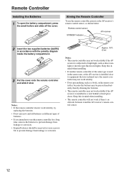
...remote controller, point it shut. Notes: • If the remote controller doesn't work if there's an obstacle between it and the AV receiver's remote control sensor. 12 Keep this in accordance with the polarity diagram inside the battery compartment. 3 Put the cover onto the remote ...controller and slide it at the AV receiver's remote control sensor, as possible to bright light, such as direct sunlight or inverter-type fluorescent lights. Approx. 16 ft. (5 m) ...
...remote controller, point it shut. Notes: • If the remote controller doesn't work if there's an obstacle between it and the AV receiver's remote control sensor. 12 Keep this in accordance with the polarity diagram inside the battery compartment. 3 Put the cover onto the remote ...controller and slide it at the AV receiver's remote control sensor, as possible to bright light, such as direct sunlight or inverter-type fluorescent lights. Approx. 16 ft. (5 m) ...

Owner Manual
Page 13
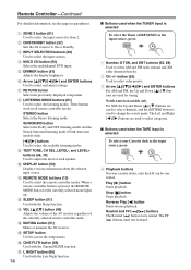
... Remote Controller The remote controller can be used to control an Onkyo cassette recorder connected via . I RECEIVER/TAPE Mode In RECEIVER/TAPE mode, you can control a TV, VCR, and satellite or cable receiver. RECEIVER/TAPE mode: see right column DVD mode: see page 15... M D/CDR C D HDD I TV, VCR and SAT/CABLE Modes With these modes, you can control RECEIVER the AV receiver and an Onkyo cassette TAPE recorder connected via . 1 2 3 4 1 5 2 36 7 4 8 9 J ON/STANDBY ZONE2 REMOTE MODE RECEIVER TAPE INPUT SELECTOR 1 2 3 V1 V2 V3 DVD M D/CDR CD HDD 4 5 6 TV V4 ...
... Remote Controller The remote controller can be used to control an Onkyo cassette recorder connected via . I RECEIVER/TAPE Mode In RECEIVER/TAPE mode, you can control a TV, VCR, and satellite or cable receiver. RECEIVER/TAPE mode: see right column DVD mode: see page 15... M D/CDR C D HDD I TV, VCR and SAT/CABLE Modes With these modes, you can control RECEIVER the AV receiver and an Onkyo cassette TAPE recorder connected via . 1 2 3 4 1 5 2 36 7 4 8 9 J ON/STANDBY ZONE2 REMOTE MODE RECEIVER TAPE INPUT SELECTOR 1 2 3 V1 V2 V3 DVD M D/CDR CD HDD 4 5 6 TV V4 ...
Owner Manual
Page 14
... ] buttons are used when the TUNER input is selected To select your Cassette deck as the input source, press: RECEIVER 8 TUNER 1 Number, D TUN, and ENT buttons (52, 58) Used to select channels, and the [ENTER] button is pressed, the REMOTE MODE button for Zone 2. P CINE FLTR button (66)...and Down [ ]/[ ] buttons are used when the TAPE input is selected To select the Tuner (AM/FM/XM) as the input source, press: RECEIVER 7 TAPE 4 Playback buttons On twin cassette decks, only deck B can be controlled. These buttons work in parentheses. J DISPLAY button (50) Displays ...
... ] buttons are used when the TUNER input is selected To select your Cassette deck as the input source, press: RECEIVER 8 TUNER 1 Number, D TUN, and ENT buttons (52, 58) Used to select channels, and the [ENTER] button is pressed, the REMOTE MODE button for Zone 2. P CINE FLTR button (66)...and Down [ ]/[ ] buttons are used when the TAPE input is selected To select the Tuner (AM/FM/XM) as the input source, press: RECEIVER 7 TAPE 4 Playback buttons On twin cassette decks, only deck B can be controlled. These buttons work in parentheses. J DISPLAY button (50) Displays ...
Owner Manual
Page 15
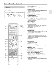
... player's onscreen setup menus. Q PLAY MODE button Selects play modes. 15 To select your DVD player as the input source, press: RECEIVER 6 DVD or 5 MULTI CH 1 2 3 4 5 6 7 8 9 J ON/STANDBY ZONE2 REMOTE MODE RECEIVER TAPE INPUT SELECTOR 1 2 3 V1 V2 V3 DVD M D/CDR C D HDD 4 5 6 TV V4 MULTI CH DVD 7 8...DVD player to enter title, chapter, and track numbers and times for locating specific points. G Playback buttons From left to control an Onkyo DVD player. P VCR, DVD, and HDD buttons Used to select VCR, HDD (hard disk drive), or DVD playback on . J DISPLAY...
... player's onscreen setup menus. Q PLAY MODE button Selects play modes. 15 To select your DVD player as the input source, press: RECEIVER 6 DVD or 5 MULTI CH 1 2 3 4 5 6 7 8 9 J ON/STANDBY ZONE2 REMOTE MODE RECEIVER TAPE INPUT SELECTOR 1 2 3 V1 V2 V3 DVD M D/CDR C D HDD 4 5 6 TV V4 MULTI CH DVD 7 8...DVD player to enter title, chapter, and track numbers and times for locating specific points. G Playback buttons From left to control an Onkyo DVD player. P VCR, DVD, and HDD buttons Used to select VCR, HDD (hard disk drive), or DVD playback on . J DISPLAY...

Owner Manual
Page 16
... D HDD G 8 9 LISTENING MODE STEREO SURROUND AUDIO SUBTITLE RANDOM REPEAT TEST TONE CH SEL LEVEL- E Playback buttons From left to control an Onkyo CD player. H MENU button Used to navigate menus on components with selectable play modes on an HDD-compatible component. L PLAY MODE button Used to... navigate menus on . To select the input source, press: RECEIVER 9 CD player C D 7 MD or CD recorder TAPE 7 or 3 Next generation HDDcompatible component TAPE V3 * If you're using an MD,...
... D HDD G 8 9 LISTENING MODE STEREO SURROUND AUDIO SUBTITLE RANDOM REPEAT TEST TONE CH SEL LEVEL- E Playback buttons From left to control an Onkyo CD player. H MENU button Used to navigate menus on components with selectable play modes on an HDD-compatible component. L PLAY MODE button Used to... navigate menus on . To select the input source, press: RECEIVER 9 CD player C D 7 MD or CD recorder TAPE 7 or 3 Next generation HDDcompatible component TAPE V3 * If you're using an MD,...
Owner Manual
Page 17
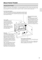
... behind the listener. About Home Theater Enjoying Home Theater Thanks to the AV receiver's superb capabilities, you can enjoy DTS and Dolby Digital. With DVDs you can enjoy Dolby Pro Logic IIx or Onkyo's own DSP surround listening modes. Corner Surround back left and right speakers These... speakers are necessary to provide a solid anchor for your listening position. The volume and quality of the LFE (Low-Frequency Effects) channel. Tip: To find the...
... behind the listener. About Home Theater Enjoying Home Theater Thanks to the AV receiver's superb capabilities, you can enjoy DTS and Dolby Digital. With DVDs you can enjoy Dolby Pro Logic IIx or Onkyo's own DSP surround listening modes. Corner Surround back left and right speakers These... speakers are necessary to provide a solid anchor for your listening position. The volume and quality of the LFE (Low-Frequency Effects) channel. Tip: To find the...
Owner Manual
Page 18
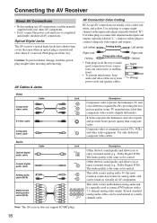
...R can be used to enjoy surround sound (e.g., Dolby Digital, DTS). Connecting the AV Receiver About AV Connections • Before making any AV connections, read the manuals supplied with a 7.1-channel analog audio output. AV Cables & Jacks AV Connection Color Coding RCA-type AV connections ...red) (Yellow) Composite video • Push plugs in all AV connections. Use only dedicated composite video cables. Note: The AV receiver does not support SCART plugs. 18 S-Video separates the luminance and color signals and provides better picture quality than composite video. Jack ...
...R can be used to enjoy surround sound (e.g., Dolby Digital, DTS). Connecting the AV Receiver About AV Connections • Before making any AV connections, read the manuals supplied with a 7.1-channel analog audio output. AV Cables & Jacks AV Connection Color Coding RCA-type AV connections ...red) (Yellow) Composite video • Push plugs in all AV connections. Use only dedicated composite video cables. Note: The AV receiver does not support SCART plugs. 18 S-Video separates the luminance and color signals and provides better picture quality than composite video. Jack ...
Owner Manual
Page 19
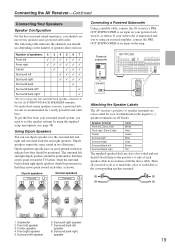
... Dipole speakers TV/screen 1 2 3 4 Normal speakers TV/screen 1 2 3 4 Connecting a Powered Subwoofer Using a suitable cable, connect the AV receiver's PRE OUT SUBWOOFER to do is recommended for the surround left and right and surround back left and right dipole speakers should be positioned. Surround...and you should use dipole speakers for a really powerful and solid bass. Surround right speaker 7. The following table indicates the channels you should attach them to match the color of each other, as shown. Front left speaker 8. To get the best ...
... Dipole speakers TV/screen 1 2 3 4 Normal speakers TV/screen 1 2 3 4 Connecting a Powered Subwoofer Using a suitable cable, connect the AV receiver's PRE OUT SUBWOOFER to do is recommended for the surround left and right and surround back left and right dipole speakers should be positioned. Surround...and you should use dipole speakers for a really powerful and solid bass. Surround right speaker 7. The following table indicates the channels you should attach them to match the color of each other, as shown. Front left speaker 8. To get the best ...
Owner Manual
Page 20
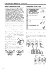
...other words, connect positive (+) terminals only to positive (+) terminals, and negative (-) terminals only to negative (-) terminals. Doing so may damage the AV receiver. • Don't connect one speaker to several terminals. Connecting the Speaker Cables 1 Strip about 5/8" (15 mm) of insulation from the wall outlet...left back right left right speaker speaker speaker speaker Front right Front left (L) SURROUND BACK SPEAKERS terminals. Doing so may damage the AV receiver. • Make sure the metal core of the connected speakers is 4 ohms or more than 6 ohms, be sure to set ...
...other words, connect positive (+) terminals only to positive (+) terminals, and negative (-) terminals only to negative (-) terminals. Doing so may damage the AV receiver. • Don't connect one speaker to several terminals. Connecting the Speaker Cables 1 Strip about 5/8" (15 mm) of insulation from the wall outlet...left back right left right speaker speaker speaker speaker Front right Front left (L) SURROUND BACK SPEAKERS terminals. Doing so may damage the AV receiver. • Make sure the metal core of the connected speakers is 4 ohms or more than 6 ohms, be sure to set ...
Owner Manual
Page 21
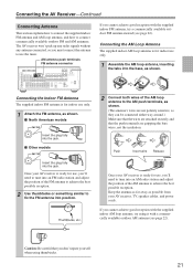
...possible reception. 2 Use thumbtacks or something similar to connect commercially available outdoor FM and AM antennas. Push Insert wire Release Once your AV receiver is ready for indoor use only. 1 Attach the FM antenna, as shown. Connecting the AM Loop Antenna The supplied indoor AM loop ... connected, so you don't injure yourself when using it with the supplied indoor FM antenna, try using thumbtacks. 21 Connecting the AV Receiver-Continued Connecting Antenna This section explains how to connect the supplied indoor FM antenna and AM loop antenna, and how to fix the...
...possible reception. 2 Use thumbtacks or something similar to connect commercially available outdoor FM and AM antennas. Push Insert wire Release Once your AV receiver is ready for indoor use only. 1 Attach the FM antenna, as shown. Connecting the AM Loop Antenna The supplied indoor AM loop ... connected, so you don't injure yourself when using it with the supplied indoor FM antenna, try using thumbtacks. 21 Connecting the AV Receiver-Continued Connecting Antenna This section explains how to connect the supplied indoor FM antenna and AM loop antenna, and how to fix the...

Owner Manual
Page 22
.... I Using a TV/FM Antenna Splitter It's best not to use a TV/FM antenna splitter, as shown. TV/FM antenna splitter To AV receiver To TV (or VCR) 22 Note that the AM loop antenna should be situated well away from power lines and other high-voltage equipment. •...; Outdoor antenna must be left connected. Outdoor antenna must be used in addition to the loop antenna, as shown. Connecting the AV Receiver-Continued Connecting an Outdoor FM Antenna If you cannot achieve good reception with local regulations to prevent electrical shock hazards. FM 75 Connecting an ...
.... I Using a TV/FM Antenna Splitter It's best not to use a TV/FM antenna splitter, as shown. TV/FM antenna splitter To AV receiver To TV (or VCR) 22 Note that the AM loop antenna should be situated well away from power lines and other high-voltage equipment. •...; Outdoor antenna must be left connected. Outdoor antenna must be used in addition to the loop antenna, as shown. Connecting the AV Receiver-Continued Connecting an Outdoor FM Antenna If you cannot achieve good reception with local regulations to prevent electrical shock hazards. FM 75 Connecting an ...


