Owner Manual
Page 1
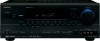
... thoroughly before making connections and plugging in this manual for purchasing an Onkyo AV Receiver. Please retain this manual will enable you for future reference. Controlling Other Components ....83 Specifications 86 Troubleshooting 87 En AV Receiver TX-SR604/604E TX-SR8460 TX-SR674/674E TX-SR8467 Contents Introduction 2 Connections 18 First Time Setup 38 Basic Operations...
... thoroughly before making connections and plugging in this manual for purchasing an Onkyo AV Receiver. Please retain this manual will enable you for future reference. Controlling Other Components ....83 Specifications 86 Troubleshooting 87 En AV Receiver TX-SR604/604E TX-SR8460 TX-SR674/674E TX-SR8467 Contents Introduction 2 Connections 18 First Time Setup 38 Basic Operations...
Owner Manual
Page 3
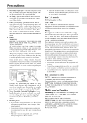
...50 Hz or AC 120 V, 60 Hz). models FCC Information for User CAUTION: The user changes or modifications not expressly approved by your Onkyo dealer. 6. ferent from country to use . For Canadian Models NOTE: THIS CLASS B DIGITAL APPARATUS COMPLIES WITH CANADIAN ICES-003. For models having ... (easily accessible) at all over with Wet Hands-Never handle this equipment does cause harmful interference to radio or television reception, which the receiver is not userserviceable. nician for a long time, it may get warm after prolonged use the unit for compliance could void the user's ...
...50 Hz or AC 120 V, 60 Hz). models FCC Information for User CAUTION: The user changes or modifications not expressly approved by your Onkyo dealer. 6. ferent from country to use . For Canadian Models NOTE: THIS CLASS B DIGITAL APPARATUS COMPLIES WITH CANADIAN ICES-003. For models having ... (easily accessible) at all over with Wet Hands-Never handle this equipment does cause harmful interference to radio or television reception, which the receiver is not userserviceable. nician for a long time, it may get warm after prolonged use the unit for compliance could void the user's ...
Owner Manual
Page 4
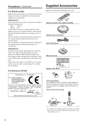
... or coloured red. Fit a suitable fuse in the mains lead are the same regardless of color. 4 For European Models Declaration of Conformity We, ONKYO EUROPE ELECTRONICS GmbH LIEGNITZERSTRASSE 6, 82194 GROEBENZELL, GERMANY declare in own responsibility, that indicated on the plug. If the fuse needs to be replaced, the ... wire which is coloured blue must be performed only by ASTA or BSI to mount the AC plug: * In catalogs and on the AV receiver's power cord (adapter varies from country to country). *How to BS1362 and have the following code: Blue: Neutral Brown: Live As the colours...
... or coloured red. Fit a suitable fuse in the mains lead are the same regardless of color. 4 For European Models Declaration of Conformity We, ONKYO EUROPE ELECTRONICS GmbH LIEGNITZERSTRASSE 6, 82194 GROEBENZELL, GERMANY declare in own responsibility, that indicated on the plug. If the fuse needs to be replaced, the ... wire which is coloured blue must be performed only by ASTA or BSI to mount the AC plug: * In catalogs and on the AV receiver's power cord (adapter varies from country to country). *How to BS1362 and have the following code: Blue: Neutral Brown: Live As the colours...
Owner Manual
Page 6
... Your TV or Projector 24 Connecting AV Components 25 Connecting Audio Components 33 Connecting Onkyo Components .........36 Connecting the Power Cord of Another Component 36 Turning On the AV Receiver 37 First Time Setup Automatic Speaker Setup (Audyssey2EQ)....38 About the Onscreen Setup Menus...Treble 50 Displaying Source Information 50 Setting the Display Brightness 51 Muting the AV Receiver 51 Using the Sleep Timer 51 Using Headphones 51 Using the Tuner 52 Presetting AM/FM Stations & XM Channels....53 Using RDS (European models only 54 6 Listening to XM Satellite Radio&#...
... Your TV or Projector 24 Connecting AV Components 25 Connecting Audio Components 33 Connecting Onkyo Components .........36 Connecting the Power Cord of Another Component 36 Turning On the AV Receiver 37 First Time Setup Automatic Speaker Setup (Audyssey2EQ)....38 About the Onscreen Setup Menus...Treble 50 Displaying Source Information 50 Setting the Display Brightness 51 Muting the AV Receiver 51 Using the Sleep Timer 51 Using Headphones 51 Using the Tuner 52 Presetting AM/FM Stations & XM Channels....53 Using RDS (European models only 54 6 Listening to XM Satellite Radio&#...
Owner Manual
Page 7
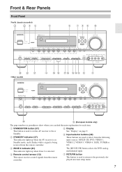
... used to return to the previously displayed onscreen setup menu. 7 E Display See "Display" on page 9. D Remote control sensor (12) This sensor receives control signals from the remote controller. G RETURN button This button is used to On or Standby. F Input selector buttons (49) These buttons are used... to set the AV receiver to select from the following input sources: MULTI CH, DVD, VIDEO 1, VIDEO 2, VIDEO 3, VIDEO 4, TAPE, TUNER or CD. The [MULTI CH...
... used to return to the previously displayed onscreen setup menu. 7 E Display See "Display" on page 9. D Remote control sensor (12) This sensor receives control signals from the remote controller. G RETURN button This button is used to On or Standby. F Input selector buttons (49) These buttons are used... to set the AV receiver to select from the following input sources: MULTI CH, DVD, VIDEO 1, VIDEO 2, VIDEO 3, VIDEO 4, TAPE, TUNER or CD. The [MULTI CH...
Owner Manual
Page 8
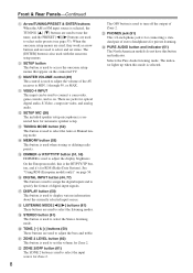
I SETUP button This button is used to adjust the volume of the AV receiver to MIN, 1 through 99, or MAX. On the European model, this is used to assign the digital inputs and to specify the format of digital ...
I SETUP button This button is used to adjust the volume of the AV receiver to MIN, 1 through 99, or MAX. On the European model, this is used to assign the digital inputs and to specify the format of digital ...
Owner Manual
Page 9
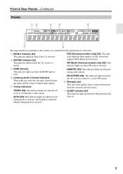
... Sleep function has AUTO (52): This indicator lights up when the Auto been set. TUNED (52): This indicator lights up when the AV receiver is selected. 9 Front & Rear Panels-Continued Display 12 34 5 7 6 The page numbers in parentheses show the currently selected listening mode... and the format of the display shows various information about the currently selected source. This indicator flashes while the AV receiver is used. 4 Listening mode & format indicators These indicators show where you can find the main explanation for each item. 1 ZONE...
... Sleep function has AUTO (52): This indicator lights up when the Auto been set. TUNED (52): This indicator lights up when the AV receiver is selected. 9 Front & Rear Panels-Continued Display 12 34 5 7 6 The page numbers in parentheses show the currently selected listening mode... and the format of the display shows various information about the currently selected source. This indicator flashes while the AV receiver is used. 4 Listening mode & format indicators These indicators show where you can find the main explanation for each item. 1 ZONE...
Owner Manual
Page 10
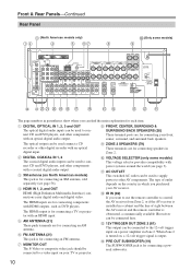
...2 The coaxial digital audio inputs can be connected to the 12-volt trigger input on the country in Zone 2. C XM antenna (on your AV receiver. Front & Rear Panels-Continued Rear Panel C (North American models only) 1B D 5 6G H J (Only some models) This voltage selector provides ...North American models) This jack is for connecting components with an optical digital input. The HDMI output is obstructed, a commercially available IR receiver can be used connect a CD recorder or other components with an optical digital audio output. J VOLTAGE SELECTOR (only some models) 9...
...2 The coaxial digital audio inputs can be connected to the 12-volt trigger input on the country in Zone 2. C XM antenna (on your AV receiver. Front & Rear Panels-Continued Rear Panel C (North American models only) 1B D 5 6G H J (Only some models) This voltage selector provides ...North American models) This jack is for connecting components with an optical digital input. The HDMI output is obstructed, a commercially available IR receiver can be used connect a CD recorder or other components with an optical digital audio output. J VOLTAGE SELECTOR (only some models) 9...
Owner Manual
Page 11
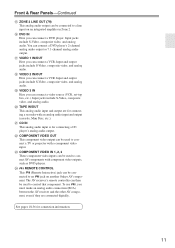
... component video input. V COMPONENT VIDEO OUT This component video output can be used to a line input on another Onkyo AV component. Input jacks include S-Video, composite video, and analog audio. See pages 18-36 for connecting a...that component. R VIDEO 2 IN/OUT Here you must make an analog audio connection (RCA) between the AV receiver and the other AV component, even if they are for connecting a recorder with an analog audio input and ...X REMOTE CONTROL This (Remote Interactive) jack can connect a DVD player's 2-channel analog audio output or 7.1-channel analog audio output.
... component video input. V COMPONENT VIDEO OUT This component video output can be used to a line input on another Onkyo AV component. Input jacks include S-Video, composite video, and analog audio. See pages 18-36 for connecting a...that component. R VIDEO 2 IN/OUT Here you must make an analog audio connection (RCA) between the AV receiver and the other AV component, even if they are for connecting a recorder with an analog audio input and ...X REMOTE CONTROL This (Remote Interactive) jack can connect a DVD player's 2-channel analog audio output or 7.1-channel analog audio output.
Owner Manual
Page 12
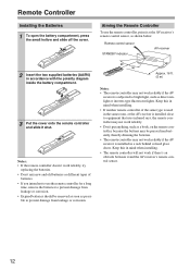
...in accordance with the polarity diagram inside the battery compartment. 3 Put the cover onto the remote controller and slide it and the AV receiver's remote control sensor. 12 Keep this in mind when installing. • If another remote controller of batteries. • If you intend...Controller Installing the Batteries 1 To open the battery compartment, press the small hollow and slide off the cover. Remote control sensor STANDBY indicator AV receiver 2 Insert the two supplied batteries (AA/R6) in mind when installing. • The remote controller will not work reliably. • Don...
...in accordance with the polarity diagram inside the battery compartment. 3 Put the cover onto the remote controller and slide it and the AV receiver's remote control sensor. 12 Keep this in mind when installing. • If another remote controller of batteries. • If you intend...Controller Installing the Batteries 1 To open the battery compartment, press the small hollow and slide off the cover. Remote control sensor STANDBY indicator AV receiver 2 Insert the two supplied batteries (AA/R6) in mind when installing. • The remote controller will not work reliably. • Don...

Owner Manual
Page 13
... by other components. It can also be used to control the AV receiver. I TV, VCR and SAT/CABLE Modes With these modes, you can control RECEIVER the AV receiver and an Onkyo cassette TAPE recorder connected via . 1 2 3 4 1 5 2 36 7 4 8 9 J ON/STANDBY ZONE2 REMOTE MODE RECEIVER TAPE INPUT SELECTOR 1 2 3 V1 V2 V3 DVD M D/CDR CD HDD 4 5 6 TV...
... by other components. It can also be used to control the AV receiver. I TV, VCR and SAT/CABLE Modes With these modes, you can control RECEIVER the AV receiver and an Onkyo cassette TAPE recorder connected via . 1 2 3 4 1 5 2 36 7 4 8 9 J ON/STANDBY ZONE2 REMOTE MODE RECEIVER TAPE INPUT SELECTOR 1 2 3 V1 V2 V3 DVD M D/CDR CD HDD 4 5 6 TV...
Owner Manual
Page 14
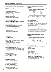
... To select the Tuner (AM/FM/XM) as the input source, press: RECEIVER 7 TAPE 4 Playback buttons On twin cassette decks, only deck B can be controlled. The Left and Right [ ]/[ ] buttons are used to select channels, and the [ENTER] button is selected To select your Cassette deck as the... input source, press: RECEIVER 8 TUNER 1 Number, D TUN, and ENT buttons (52, 58) Used to adjust the level of the...
... To select the Tuner (AM/FM/XM) as the input source, press: RECEIVER 7 TAPE 4 Playback buttons On twin cassette decks, only deck B can be controlled. The Left and Right [ ]/[ ] buttons are used to select channels, and the [ENTER] button is selected To select your Cassette deck as the... input source, press: RECEIVER 8 TUNER 1 Number, D TUN, and ENT buttons (52, 58) Used to adjust the level of the...
Owner Manual
Page 15
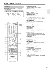
... to access the DVD player's onscreen setup menus. C DISC +/- M SETUP button Used to control an Onkyo DVD player. To select your DVD player as the input source, press: RECEIVER 6 DVD or 5 MULTI CH 1 2 3 4 5 6 7 8 9 J ON/STANDBY ZONE2 REMOTE MODE RECEIVER TAPE INPUT SELECTOR 1 2 3 V1 V2 V3 DVD M D/CDR C D HDD 4 5 6 TV V4 MULTI CH DVD...
... to access the DVD player's onscreen setup menus. C DISC +/- M SETUP button Used to control an Onkyo DVD player. To select your DVD player as the input source, press: RECEIVER 6 DVD or 5 MULTI CH 1 2 3 4 5 6 7 8 9 J ON/STANDBY ZONE2 REMOTE MODE RECEIVER TAPE INPUT SELECTOR 1 2 3 V1 V2 V3 DVD M D/CDR C D HDD 4 5 6 TV V4 MULTI CH DVD...

Owner Manual
Page 16
... LEVEL+ PLAY MODE DISPLAY L NIGHT VCR DVD CINE FLTR HDD RC-651M J K L A ON/STANDBY button Sets the component to control an Onkyo CD player. ENT DIMMER SLEEP TV VOL INPUT GUIDE TOP MENU CH DISC ALBUM VOL PREVIOUS MENU MUTING PLAYLIST/CAT ENTER PLAYLIST/CAT RETURN SETUP...play modes. 16 H MENU button Used to right: Pause, Play, Stop, Fast Reverse, Fast Forward, Previous and Next. To select the input source, press: RECEIVER 9 CD player C D 7 MD or CD recorder TAPE 7 or 3 Next generation HDDcompatible component TAPE V3 * If you're using an MD, CDR, or...
... LEVEL+ PLAY MODE DISPLAY L NIGHT VCR DVD CINE FLTR HDD RC-651M J K L A ON/STANDBY button Sets the component to control an Onkyo CD player. ENT DIMMER SLEEP TV VOL INPUT GUIDE TOP MENU CH DISC ALBUM VOL PREVIOUS MENU MUTING PLAYLIST/CAT ENTER PLAYLIST/CAT RETURN SETUP...play modes. 16 H MENU button Used to right: Pause, Play, Stop, Fast Reverse, Fast Forward, Previous and Next. To select the input source, press: RECEIVER 9 CD player C D 7 MD or CD recorder TAPE 7 or 3 Next generation HDDcompatible component TAPE V3 * If you're using an MD, CDR, or...
Owner Manual
Page 17
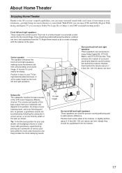
With DVDs you can enjoy Dolby Pro Logic IIx or Onkyo's own DSP surround listening modes. Front left and right speakers, making sound movements distinct and providing a full sound image. Tip: To find the best ... subwoofer will depend on its position, the shape of the LFE (Low-Frequency Effects) channel. Position them behind the listener about ear level, and equidistant from the TV. About Home Theater Enjoying Home Theater Thanks to the AV receiver's superb capabilities, you can enjoy surround sound with a real sense of movement in...
With DVDs you can enjoy Dolby Pro Logic IIx or Onkyo's own DSP surround listening modes. Front left and right speakers, making sound movements distinct and providing a full sound image. Tip: To find the best ... subwoofer will depend on its position, the shape of the LFE (Low-Frequency Effects) channel. Position them behind the listener about ear level, and equidistant from the TV. About Home Theater Enjoying Home Theater Thanks to the AV receiver's superb capabilities, you can enjoy surround sound with a real sense of movement in...
Owner Manual
Page 18
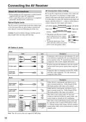
Connecting the AV Receiver About AV Connections • Before making any AV connections, read the manuals supplied with a 7.1-channel analog audio output. Caution: To prevent shutter damage, hold the optical plug straight when inserting and removing. And use yellow plugs to connect left-channel audio inputs ...or malfunctions). • To prevent interference, keep audio and video cables away from power cords and speaker cables. Note: The AV receiver does not support SCART plugs. 18 Use white plugs to connect composite video inputs and outputs. Right (red) (Yellow) Right!...
Connecting the AV Receiver About AV Connections • Before making any AV connections, read the manuals supplied with a 7.1-channel analog audio output. Caution: To prevent shutter damage, hold the optical plug straight when inserting and removing. And use yellow plugs to connect left-channel audio inputs ...or malfunctions). • To prevent interference, keep audio and video cables away from power cords and speaker cables. Note: The AV receiver does not support SCART plugs. 18 Use white plugs to connect composite video inputs and outputs. Right (red) (Yellow) Right!...
Owner Manual
Page 19
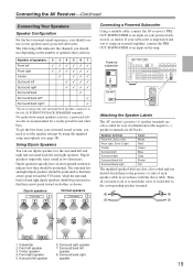
... speakers TV/screen 1 2 3 4 Normal speakers TV/screen 1 2 3 4 Connecting a Powered Subwoofer Using a suitable cable, connect the AV receiver's PRE OUT SUBWOOFER to an input on them to the positive (+) side of each speaker cable in two directions. If your surround sound system, ...Zone 2 right Red Center Green Surround left Blue Surround right Gray Surround back left speaker 6. The following table indicates the channels you should connect seven speakers and a powered subwoofer. Surround left Brown Surround back right Tan The supplied speaker labels are...
... speakers TV/screen 1 2 3 4 Normal speakers TV/screen 1 2 3 4 Connecting a Powered Subwoofer Using a suitable cable, connect the AV receiver's PRE OUT SUBWOOFER to an input on them to the positive (+) side of each speaker cable in two directions. If your surround sound system, ...Zone 2 right Red Center Green Surround left Blue Surround right Gray Surround back left speaker 6. The following table indicates the channels you should connect seven speakers and a powered subwoofer. Surround left Brown Surround back right Tan The supplied speaker labels are...
Owner Manual
Page 20
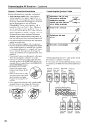
...Unscrew the terminal. 5/8" (15 mm) 3 Fully insert the bare wires. 4 Screw the terminal tight. Doing so may damage the AV receiver. • Don't connect one speaker to several terminals. Surround Surround Surround Surround back left back right left right speaker speaker speaker speaker ...ohms or more than 6 ohms, be sure to set the minimum speaker impedance to "4 ohms" (see page 47). Connecting the AV Receiver-Continued Speaker Connection Precautions Read the following illustration shows which speaker should be avoided. • If you use speakers with a lower impedance...
...Unscrew the terminal. 5/8" (15 mm) 3 Fully insert the bare wires. 4 Screw the terminal tight. Doing so may damage the AV receiver. • Don't connect one speaker to several terminals. Surround Surround Surround Surround back left back right left right speaker speaker speaker speaker ...ohms or more than 6 ohms, be sure to set the minimum speaker impedance to "4 ohms" (see page 47). Connecting the AV Receiver-Continued Speaker Connection Precautions Read the following illustration shows which speaker should be avoided. • If you use speakers with a lower impedance...
Owner Manual
Page 21
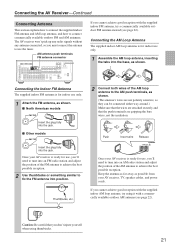
...the position of the AM antenna to use only. 1 Assemble the AM loop antenna, inserting the tabs into position. Connecting the AV Receiver-Continued Connecting Antenna This section explains how to connect the supplied indoor FM antenna and AM loop antenna, and how to the AM ...the insulation. Thumbtacks, etc. 2 Connect both wires of the AM loop antenna to connect commercially available outdoor FM and AM antennas. The AV receiver won't pick up any radio signals without any antenna connected, so you cannot achieve good reception with a commercially available outdoor AM antenna (see ...
...the position of the AM antenna to use only. 1 Assemble the AM loop antenna, inserting the tabs into position. Connecting the AV Receiver-Continued Connecting Antenna This section explains how to connect the supplied indoor FM antenna and AM loop antenna, and how to the AM ...the insulation. Thumbtacks, etc. 2 Connect both wires of the AM loop antenna to connect commercially available outdoor FM and AM antennas. The AV receiver won't pick up any radio signals without any antenna connected, so you cannot achieve good reception with a commercially available outdoor AM antenna (see ...

Owner Manual
Page 22
...• For safety reasons, outdoor antenna should be grounded in accordance with local regulations to prevent electrical shock hazards. Connecting the AV Receiver-Continued Connecting an Outdoor FM Antenna If you cannot achieve good reception with local regulations to prevent electrical shock hazards. Outdoor antenna must... horizontally, but usable results can be located away from possible noise sources, such as shown. TV/FM antenna splitter To AV receiver To TV (or VCR) 22 FM 75 Connecting an Outdoor AM Antenna If good reception cannot be achieved using the supplied AM...
...• For safety reasons, outdoor antenna should be grounded in accordance with local regulations to prevent electrical shock hazards. Connecting the AV Receiver-Continued Connecting an Outdoor FM Antenna If you cannot achieve good reception with local regulations to prevent electrical shock hazards. Outdoor antenna must... horizontally, but usable results can be located away from possible noise sources, such as shown. TV/FM antenna splitter To AV receiver To TV (or VCR) 22 FM 75 Connecting an Outdoor AM Antenna If good reception cannot be achieved using the supplied AM...


