
Owner Manual
Page 1
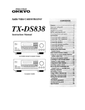
... 36 Recording a source 37 Using TAPE-2 MONITOR 40 Selecting a Surround mode 42 Setting the Surround mode parameters 44 TX-DS838 parameters 46 Troubleshooting guide 47 Specifications 49 Artistry in Sound ONKYQ Audio Video Control Receiver TX-DS838 Instruction Manual = = 00 o 0 *O 1 I I I 1 I I OOO All models except European models c= 0 0 0O CO 0 0) I I I I I 000 European models ...26 Listening to your favorite source 29 Tuning in a radio station 31 Using preset radio stations 32 Selecting a preset station 33 Receiving RDS broadcasts (Not available in the U.S.
... 36 Recording a source 37 Using TAPE-2 MONITOR 40 Selecting a Surround mode 42 Setting the Surround mode parameters 44 TX-DS838 parameters 46 Troubleshooting guide 47 Specifications 49 Artistry in Sound ONKYQ Audio Video Control Receiver TX-DS838 Instruction Manual = = 00 o 0 *O 1 I I I 1 I I OOO All models except European models c= 0 0 0O CO 0 0) I I I I I 000 European models ...26 Listening to your favorite source 29 Tuning in a radio station 31 Using preset radio stations 32 Selecting a preset station 33 Receiving RDS broadcasts (Not available in the U.S.
Owner Manual
Page 2
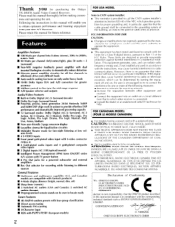
... 8 ohms (stereo), 20Hz to 20kHz, 0.08% THD ■ 90 Watts per channel into an outlet on a circuit different from your new A/V Receiver. YAMAZOE ONKYO EUROPE ELECTRONICS GMBH These limits are compatible with Xantech products) ■ 4-Mode display dimmer (bright, normal, dim, off and on, the user is ... cord with the limits for help. Please retain this manual thoroughly before making connections and operating the unit. ufacturer for purchasing the Onkyo TX-DS838 Audio Video Control Receiver. Thank you to obtain optimum performance and listening enjoyment from that the...
... 8 ohms (stereo), 20Hz to 20kHz, 0.08% THD ■ 90 Watts per channel into an outlet on a circuit different from your new A/V Receiver. YAMAZOE ONKYO EUROPE ELECTRONICS GMBH These limits are compatible with Xantech products) ■ 4-Mode display dimmer (bright, normal, dim, off and on, the user is ... cord with the limits for help. Please retain this manual thoroughly before making connections and operating the unit. ufacturer for purchasing the Onkyo TX-DS838 Audio Video Control Receiver. Thank you to obtain optimum performance and listening enjoyment from that the...
Owner Manual
Page 3
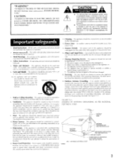
... described in the literature accompanying the product. or E. The user should be walked on the appliance. 11. If an outside antenna is connected to the receiver, be unplugged from power lines. 15. Read Instructions -All the safety and operating instructions should be read the following information: The polarization of at least...
... described in the literature accompanying the product. or E. The user should be walked on the appliance. 11. If an outside antenna is connected to the receiver, be unplugged from power lines. 15. Read Instructions -All the safety and operating instructions should be read the following information: The polarization of at least...
Owner Manual
Page 7
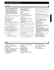
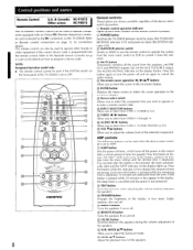
...and indicator [22] (1) POWER switch and POWER indicator (SYSTEM switch and SYSTEM indicator on the European models) and STAND-BY/RECEIVED indicator [17, 29] The STAND-BY/RECEIVED indicator lights up . Turning it may be impossible to set with the display turned off, the display will return to -4 input... the knob is set the MASTER VOLUME level to its maximum, it will light up for the selected speakers lights up each time a signal is received from the remote control. • Remote control sensor [5] ® AC-3 indicator [42] C) DIMMER button Used to change the brightness of the ...
...and indicator [22] (1) POWER switch and POWER indicator (SYSTEM switch and SYSTEM indicator on the European models) and STAND-BY/RECEIVED indicator [17, 29] The STAND-BY/RECEIVED indicator lights up . Turning it may be impossible to set with the display turned off, the display will return to -4 input... the knob is set the MASTER VOLUME level to its maximum, it will light up for the selected speakers lights up each time a signal is received from the remote control. • Remote control sensor [5] ® AC-3 indicator [42] C) DIMMER button Used to change the brightness of the ...
Owner Manual
Page 8
NOTE: European/Australian model only: • The remote control cannot be used to operate components equipped with an Onkyo RI (Remote Interactive) connector and connected to the RI connectors on the TX-D5838. The AUDIO MUTING indicator on again to cancel the audio muting. 0 On-screen cursor operation -4 /... indicator is displayed. With each time a button on the remote control is pressed. ® POWER button Switches the TX-DS838 between stand-by status (the STAND-BY/ RECEIVED indicator is lit) and power-on status (the SYSTEM indicator is lit). ® MAIN/SUB selector switch Switch to...
NOTE: European/Australian model only: • The remote control cannot be used to operate components equipped with an Onkyo RI (Remote Interactive) connector and connected to the RI connectors on the TX-D5838. The AUDIO MUTING indicator on again to cancel the audio muting. 0 On-screen cursor operation -4 /... indicator is displayed. With each time a button on the remote control is pressed. ® POWER button Switches the TX-DS838 between stand-by status (the STAND-BY/ RECEIVED indicator is lit) and power-on status (the SYSTEM indicator is lit). ® MAIN/SUB selector switch Switch to...
Owner Manual
Page 14
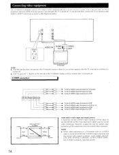
...a VDP To the S-VIDEO output terminal of a DVD or TV To the S-VIDEO output terminal of a VCR To the S-VIDEO input terminal of the TX-DS838's display and five minutes later it also turns off . However, a signal fed into the S-VIDEO input connector will be output to the MONITOR OUTPUT from...turned off. • If the TV goes off, "•" flashes on , and turns off the receiver's power 5 seconds after the TV is turned on the left side of a VCR S Input Video Video signal flow TX-DS838 S Priority Output Video Video and S-VIDEO input and output priority A signal fed into the normal video...
...a VDP To the S-VIDEO output terminal of a DVD or TV To the S-VIDEO output terminal of a VCR To the S-VIDEO input terminal of the TX-DS838's display and five minutes later it also turns off . However, a signal fed into the S-VIDEO input connector will be output to the MONITOR OUTPUT from...turned off. • If the TV goes off, "•" flashes on , and turns off the receiver's power 5 seconds after the TV is turned on the left side of a VCR S Input Video Video signal flow TX-DS838 S Priority Output Video Video and S-VIDEO input and output priority A signal fed into the normal video...
Owner Manual
Page 17
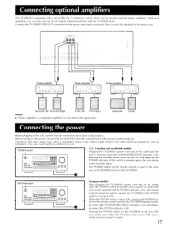
... that the MASTER VOLUME control knob is fully turned counterclockwise. With such amplifiers, you to the stand-by status (the STAND-BY/RECEIVED indicator is lit). Connect the TX-DS838's PRE OUT connectors to the power amp input connectors, then connect the speakers to the power amp. '0, 50\ I0 q, ck...cord into an AC outlet, press the SYSTEM switch to put the unit in power-on the remote control switches the TX-DS838 between standby status (the STAND-BY/RECEIVED indicator is lit) and poweron status (the SYSTEM indicator is pressed again, the unit returns to connect external power amplifiers...
... that the MASTER VOLUME control knob is fully turned counterclockwise. With such amplifiers, you to the stand-by status (the STAND-BY/RECEIVED indicator is lit). Connect the TX-DS838's PRE OUT connectors to the power amp input connectors, then connect the speakers to the power amp. '0, 50\ I0 q, ck...cord into an AC outlet, press the SYSTEM switch to put the unit in power-on the remote control switches the TX-DS838 between standby status (the STAND-BY/RECEIVED indicator is lit) and poweron status (the SYSTEM indicator is pressed again, the unit returns to connect external power amplifiers...

Owner Manual
Page 19
...Others 19 Connecting antennas T-shaped FM antenna and AM loop antenna The T-shaped FM antenna is for indoor use only. If clear signals cannot he received using only the enclosed T-shaped FM antenna or AM loop antenna, connect an outdoor FM or outdoor AM antenna as follows: • Keep the...as far as possible away from noise sources, such as neon signs and busy roads. • Do not position it until the clearest signal is received. U.S. & Canada Others Outdoor AM antenna The outdoor AM antenna will be more effective if it in the T-shaped arrangement giving the least amount ...
...Others 19 Connecting antennas T-shaped FM antenna and AM loop antenna The T-shaped FM antenna is for indoor use only. If clear signals cannot he received using only the enclosed T-shaped FM antenna or AM loop antenna, connect an outdoor FM or outdoor AM antenna as follows: • Keep the...as far as possible away from noise sources, such as neon signs and busy roads. • Do not position it until the clearest signal is received. U.S. & Canada Others Outdoor AM antenna The outdoor AM antenna will be more effective if it in the T-shaped arrangement giving the least amount ...
Owner Manual
Page 20
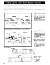
... (Main room) Speaker (Main room) Power , supply Power amplifier Remote control IR Receiver, Dinky Link or J-Box Receiver Speaker (Sub room) Speaker (Sub room) N-J 1. Speaker Sub room) 2. Emitter (e) SUB ROOM N 4. Onkyo components (a) Speaker (Main room) TX-DS838 Speaker (Main room) 4. Speaker \ (Sub room) 3. Components(d) TX-DS838 Connec ing block 1. Make the connections described above : 4. Install Remote Emitter...
... (Main room) Speaker (Main room) Power , supply Power amplifier Remote control IR Receiver, Dinky Link or J-Box Receiver Speaker (Sub room) Speaker (Sub room) N-J 1. Speaker Sub room) 2. Emitter (e) SUB ROOM N 4. Onkyo components (a) Speaker (Main room) TX-DS838 Speaker (Main room) 4. Speaker \ (Sub room) 3. Components(d) TX-DS838 Connec ing block 1. Make the connections described above : 4. Install Remote Emitter...
Owner Manual
Page 21
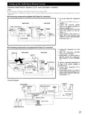
...\ Sub room) 1. Install Xantech's J-Box Receiver or Dinky Link in the sub-room, then connect it to the Connecting Block in the main room. 01.;' ) ■ Connecting components not equipped with Onkyo RI connectors MAIN ROOM SUB ROOM 1. Power ...to the speaker terminals on the power amplifier. (E2_;) 4. Be sure the components are correctly connected. • Connecting components equipped with Onkyo RI connectors 3. Connect the TX-DS838 to the TX-DS838. 5. FICJII I Oyw.erri /I I n I -O``ouT ray Terminal FRONT SPEAKERS A Connecting block Emitter Power supply 21 Ctr IU ...
...\ Sub room) 1. Install Xantech's J-Box Receiver or Dinky Link in the sub-room, then connect it to the Connecting Block in the main room. 01.;' ) ■ Connecting components not equipped with Onkyo RI connectors MAIN ROOM SUB ROOM 1. Power ...to the speaker terminals on the power amplifier. (E2_;) 4. Be sure the components are correctly connected. • Connecting components equipped with Onkyo RI connectors 3. Connect the TX-DS838 to the TX-DS838. 5. FICJII I Oyw.erri /I I n I -O``ouT ray Terminal FRONT SPEAKERS A Connecting block Emitter Power supply 21 Ctr IU ...
Owner Manual
Page 23
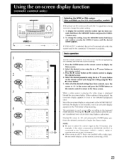
If "OSD AUTO" is being received, change the system setting. 1. When nothing is selected, the unit will automatically select the system used by connecting a VCR. 23 The parameters in the screen ...
If "OSD AUTO" is being received, change the system setting. 1. When nothing is selected, the unit will automatically select the system used by connecting a VCR. 23 The parameters in the screen ...
Owner Manual
Page 25
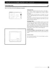
... input signal is performed. Immediate Display These characters appear on the TV/monitor screen for 3 seconds each time an operation is received. Character Position You can be selected for it is easy to OFF, NORMAL or BLACK. When there is selected, the characters...the input signal. Using the on-screen display function (remote control only) Screen Setup screen When Screen Setup is selected, the following screen appears: 10.1\TX.,C40. ** Screen Setup ** Background Color A BLUE -1 Color 3 = GREEN GB Superimpose Mode = NORMAL GM Smmediate Display , ON BrI Character Position...
... input signal is performed. Immediate Display These characters appear on the TV/monitor screen for 3 seconds each time an operation is received. Character Position You can be selected for it is easy to OFF, NORMAL or BLACK. When there is selected, the characters...the input signal. Using the on-screen display function (remote control only) Screen Setup screen When Screen Setup is selected, the following screen appears: 10.1\TX.,C40. ** Screen Setup ** Background Color A BLUE -1 Color 3 = GREEN GB Superimpose Mode = NORMAL GM Smmediate Display , ON BrI Character Position...

Owner Manual
Page 31
... the entered frequency. Tuning in a radio station Make sure that the T-2 MONITOR and AUDIO MUTING indicators are scanned and tuning automatically stops when a broadcast is received.
... the entered frequency. Tuning in a radio station Make sure that the T-2 MONITOR and AUDIO MUTING indicators are scanned and tuning automatically stops when a broadcast is received.
Owner Manual
Page 34
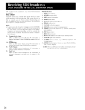
What is displayed. If unusual characters appear in the TX-DS838's display may not be correctly displayed by the radio station. TP: Traffic Program When an RDS station broadcasting TP information is selected, ...VARIED (various talk programs, e.g. RT: Radio Text When an RDS station broadcasting RT information is selected, information received from the station is displayed. CLASSICS (serious classics, e.g. Receiving RDS broadcasts o aval as the ones broadcast by the TX-DS838. INFO (general information) 4. SPORT (sports news) 5. Many FM stations now transmit RDS signals which give...
What is displayed. If unusual characters appear in the TX-DS838's display may not be correctly displayed by the radio station. TP: Traffic Program When an RDS station broadcasting TP information is selected, ...VARIED (various talk programs, e.g. RT: Radio Text When an RDS station broadcasting RT information is selected, information received from the station is displayed. CLASSICS (serious classics, e.g. Receiving RDS broadcasts o aval as the ones broadcast by the TX-DS838. INFO (general information) 4. SPORT (sports news) 5. Many FM stations now transmit RDS signals which give...

Owner Manual
Page 35
.... (Refer to start searching for other areas) O PTY/TP DISPLAY =i=i 0 0 1 0 (o o (3) SCAN 08= I I • 1 Searching for more time is received, scan- When a station of the DISPLAY button on page 36 for a station of the 3 desired program type. tion cannot be used . 1. Press the PTY/TP... If no characters have been entered, only the frequency is not broadcasting RDS signals, this func- Searching for 3 seconds, RT information is received, the characters will scroll across the display. If "Not find" appears on the display. ning stops for example "ROCK M". When RT ...
.... (Refer to start searching for other areas) O PTY/TP DISPLAY =i=i 0 0 1 0 (o o (3) SCAN 08= I I • 1 Searching for more time is received, scan- When a station of the DISPLAY button on page 36 for a station of the 3 desired program type. tion cannot be used . 1. Press the PTY/TP... If no characters have been entered, only the frequency is not broadcasting RDS signals, this func- Searching for 3 seconds, RT information is received, the characters will scroll across the display. If "Not find" appears on the display. ning stops for example "ROCK M". When RT ...

Owner Manual
Page 36
... desired station. (Refer to Selecting a preset station on page 33.) 2. If a button is not pressed within 16 seconds, the operation will be given the name "ONKYO". 1. After the selected character is displayed and characters cannot be entered. 2, 5, 2, 5 1,1 3, 4, 4 tr I ,, = ' oo oo(6),:o) I I I I 0 I I I I I...FM MUTE/ MODE button. The first character and the cursor flash alternately. 3. Press the CHARACTER button. 3. Entering characters While receiving a preset FM or AM station, a maximum of 8 characters consisting of letters, numbers and some symbols can be entered: ABCDEFGHI...
... desired station. (Refer to Selecting a preset station on page 33.) 2. If a button is not pressed within 16 seconds, the operation will be given the name "ONKYO". 1. After the selected character is displayed and characters cannot be entered. 2, 5, 2, 5 1,1 3, 4, 4 tr I ,, = ' oo oo(6),:o) I I I I 0 I I I I I...FM MUTE/ MODE button. The first character and the cursor flash alternately. 3. Press the CHARACTER button. 3. Entering characters While receiving a preset FM or AM station, a maximum of 8 characters consisting of letters, numbers and some symbols can be entered: ABCDEFGHI...
Owner Manual
Page 39
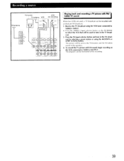
... by selecting a preset station or using the VCR tuner connected to VIDEO-1 INPUT. 2. The program can be recorded with FM sound, begin recording on the TX-DC838 to select the VCR that will be monitored while recording. 39 Press the FM input selector button and tune in the TV broadcast. 3. Press... to the speakers. 4. The picture will be used , a TV broadcast can be sent to the TV/monitor and the FM stereo sound to VIDEO-2 OUTPUT. Receive the TV broadcast using the Al DOWN or UP O. To record the TV picture with a simulcast FM broadcast. 1. TUNING button.
... by selecting a preset station or using the VCR tuner connected to VIDEO-1 INPUT. 2. The program can be recorded with FM sound, begin recording on the TX-DC838 to select the VCR that will be monitored while recording. 39 Press the FM input selector button and tune in the TV broadcast. 3. Press... to the speakers. 4. The picture will be used , a TV broadcast can be sent to the TV/monitor and the FM stereo sound to VIDEO-2 OUTPUT. Receive the TV broadcast using the Al DOWN or UP O. To record the TV picture with a simulcast FM broadcast. 1. TUNING button.

Owner Manual
Page 47
...too strong. • Use a T-shaped antenna. High-pitched noise or buzzing noise on the TX-DS838 front panel to a different position. FM TUNED and STEREO indicators light • The station signal ...or no power • The amplifier protection circuitry has been • Contact your Onkyo service center. to the respective instruction manuals of the outdoor antenna. activated. - ... the AM antenna terminals. control does not. ONTrstoIntegra 47 The sound level will be received • The AM loop antenna is not attached. • Connect the enclosed AM...
...too strong. • Use a T-shaped antenna. High-pitched noise or buzzing noise on the TX-DS838 front panel to a different position. FM TUNED and STEREO indicators light • The station signal ...or no power • The amplifier protection circuitry has been • Contact your Onkyo service center. to the respective instruction manuals of the outdoor antenna. activated. - ... the AM antenna terminals. control does not. ONTrstoIntegra 47 The sound level will be received • The AM loop antenna is not attached. • Connect the enclosed AM...


