Owner Manual
Page 2
... following code: Blue: Neutral Brown: Live As the colours of the wires in this manual for purchasing Me Onkyo TX-8511 Audio Video Control Rlteiier. Check for a receiver) ■ Multiroom Remote System capability (USA models are compatible with Xantech TM accessories) • 4 Audio and 2 AV inputs &#... and some other models only) I Direct access tuning II Motor-driven, precision volume control III Headphone jack p Audio mute, sleep timer (via remote) I Battery-free memory backup • New non-resonant feet • New slip-free rotary volume knob ■ R I ED MOULDED PLUG...
... following code: Blue: Neutral Brown: Live As the colours of the wires in this manual for purchasing Me Onkyo TX-8511 Audio Video Control Rlteiier. Check for a receiver) ■ Multiroom Remote System capability (USA models are compatible with Xantech TM accessories) • 4 Audio and 2 AV inputs &#... and some other models only) I Direct access tuning II Motor-driven, precision volume control III Headphone jack p Audio mute, sleep timer (via remote) I Battery-free memory backup • New non-resonant feet • New slip-free rotary volume knob ■ R I ED MOULDED PLUG...
Owner Manual
Page 4
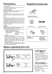
...he removed from AC outlet when not in areas where the power supply is not correct, insert a screwdriver into the grs)eve in your Onkyo authorized service station. 4. Determine the proper voltage for use rough material,.thinners, alcohol or other models) (Worldwide model only) 75/300 ...equipped with a switch that of the copyright holder. 3. So power cord should wipe the front and rear panels and the cabinet with a clean cloth. oGoo Remote control RC-329S (1) Battery (size AA, R6, or UM-3) (2) et AM loop antenna (1) T-shaped FM antenna (1) 0 (Worldwide and some other ...
...he removed from AC outlet when not in areas where the power supply is not correct, insert a screwdriver into the grs)eve in your Onkyo authorized service station. 4. Determine the proper voltage for use rough material,.thinners, alcohol or other models) (Worldwide model only) 75/300 ...equipped with a switch that of the copyright holder. 3. So power cord should wipe the front and rear panels and the cabinet with a clean cloth. oGoo Remote control RC-329S (1) Battery (size AA, R6, or UM-3) (2) et AM loop antenna (1) T-shaped FM antenna (1) 0 (Worldwide and some other ...
Owner Manual
Page 5
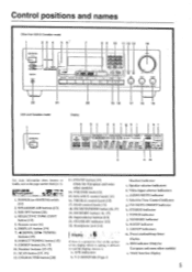
... 6' 7 ONSVi r0 ralat, CORDS /pad .r•Va Ira 4.0. 0•100, MK 0 8 9 10 11 12 13 14 Is PIO u CO i Ttit!) ) 4.1•04.400 TX 5,, 22 21 USA and Canadian model 20 19 18 17 16 15 Display a d e f ah i k I -APRRR STEREO MODE ''•MOOE [ULM MU WIN I . SPEAKERS A...) indicator c. FM MUTE ON/OFF indicator h. MR OFF button [261 4. FM MUTE/NIODE button [16, 171 19. Speaker selector indicators d. Remote sensor 161 6. VOLUNIE knob 1131 15. RDS indicator (Only for European and some other models) 14. BALANCE control knob [131 16. Selective Tone...
... 6' 7 ONSVi r0 ralat, CORDS /pad .r•Va Ira 4.0. 0•100, MK 0 8 9 10 11 12 13 14 Is PIO u CO i Ttit!) ) 4.1•04.400 TX 5,, 22 21 USA and Canadian model 20 19 18 17 16 15 Display a d e f ah i k I -APRRR STEREO MODE ''•MOOE [ULM MU WIN I . SPEAKERS A...) indicator c. FM MUTE ON/OFF indicator h. MR OFF button [261 4. FM MUTE/NIODE button [16, 171 19. Speaker selector indicators d. Remote sensor 161 6. VOLUNIE knob 1131 15. RDS indicator (Only for European and some other models) 14. BALANCE control knob [131 16. Selective Tone...
Owner Manual
Page 6
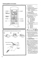
...[14] 8. bt DECK4 •,.. cfn -IMt DECICS CP ,±1 1. fY±-OCJ-W1L75n 1=1 A CI CI (= 4se VOLUME C] ONKYO REMOTE CONTROLLER RC-MS 6. INI'UT SELECTOR buttons [13] 4. VOLUME A/V buttons [13, 26] When you have made the RI connections mentioned on ... UM-3)-size batteries into the remote control according to use . • The TX-851I comes equipped with this unit behind such a door may prevent proper remote control operation. SLEEP button [14] 7. Control positions and names 1. O O (-3O Remote control sensor STAND-BY indicator 30' 30* TX-8511 approx. 5 m (16 ...
...[14] 8. bt DECK4 •,.. cfn -IMt DECICS CP ,±1 1. fY±-OCJ-W1L75n 1=1 A CI CI (= 4se VOLUME C] ONKYO REMOTE CONTROLLER RC-MS 6. INI'UT SELECTOR buttons [13] 4. VOLUME A/V buttons [13, 26] When you have made the RI connections mentioned on ... UM-3)-size batteries into the remote control according to use . • The TX-851I comes equipped with this unit behind such a door may prevent proper remote control operation. SLEEP button [14] 7. Control positions and names 1. O O (-3O Remote control sensor STAND-BY indicator 30' 30* TX-8511 approx. 5 m (16 ...

Owner Manual
Page 7
... Onkyo turntables. • An R I mark, never connect it to the green or gray connector with the fTTg'.: mark. NOTE: • To enable proper remote control operation, both the RI cables and the audio cables must be connected to the black connector with the R I remote... O OOO IPLA I 1.O. i•i U • It.. I O O OO 0 O1 () () () O 0 O C) C). Connect the remote control cable to the units. • This unit's remote control cannot be operated using the remote control included with an R I connector. To wall outlet CAUTION: Do not plug in the power cord until all...
... Onkyo turntables. • An R I mark, never connect it to the green or gray connector with the fTTg'.: mark. NOTE: • To enable proper remote control operation, both the RI cables and the audio cables must be connected to the black connector with the R I remote... O OOO IPLA I 1.O. i•i U • It.. I O O OO 0 O1 () () () O 0 O C) C). Connect the remote control cable to the units. • This unit's remote control cannot be operated using the remote control included with an R I connector. To wall outlet CAUTION: Do not plug in the power cord until all...
Owner Manual
Page 8
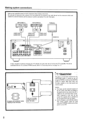
...• Dm_orLmie. ■ ONICY0•n•a WOW Vi0t0 mi 0t044. Be careful that other than USA and Canadian models) on the front panel and remote control. On each pair of each component when making connections. MOM ,. We do not exceed the capacity that is printed on page 10, 110 4-- M10...FM antenna. (Refer to Connecting anten»ax on the rear panel above the AC outlets. • (For the European and worldwide models) The remote control cannot be interference between the 'I VIDEO IN VIDEO OUT AUDIO IN AUDIO OUT VIDEO IN 0400.4 Wlf iG i ts Irt.004•00.0....
...• Dm_orLmie. ■ ONICY0•n•a WOW Vi0t0 mi 0t044. Be careful that other than USA and Canadian models) on the front panel and remote control. On each pair of each component when making connections. MOM ,. We do not exceed the capacity that is printed on page 10, 110 4-- M10...FM antenna. (Refer to Connecting anten»ax on the rear panel above the AC outlets. • (For the European and worldwide models) The remote control cannot be interference between the 'I VIDEO IN VIDEO OUT AUDIO IN AUDIO OUT VIDEO IN 0400.4 Wlf iG i ts Irt.004•00.0....
Owner Manual
Page 12
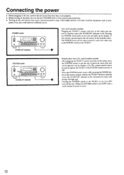
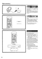
The POWER button on the remote control is used to operate the TX-8511 if the SYSTEM switch is not set to ON. The remote control cannot be used in the same way as com- When the SYSTEM switch is set to put the unit in power-on status (the ... unit returns to ON, pressing the POWER button on the remote control switches the TX-85I I between stand-by status. If so, use a wall outlet on the TX-851 I . POWER switch • STAND-BY indicator 000 U.S. and Canadian models: After plugging the TX-8511's power cord into an AC outlet puts the unit in stand...
The POWER button on the remote control is used to operate the TX-8511 if the SYSTEM switch is not set to ON. The remote control cannot be used in the same way as com- When the SYSTEM switch is set to put the unit in power-on status (the ... unit returns to ON, pressing the POWER button on the remote control switches the TX-85I I between stand-by status. If so, use a wall outlet on the TX-851 I . POWER switch • STAND-BY indicator 000 U.S. and Canadian models: After plugging the TX-8511's power cord into an AC outlet puts the unit in stand...
Owner Manual
Page 13
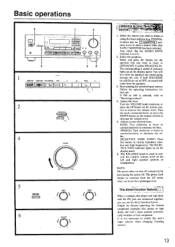
... indicator is not necessary to (SPEAKERS A and/or SPEAKERS B). The corresponding A and/or B indicator lights up on the remote control to attenuate the tre- Start playing the selected input source. Adjust the level. remote control to clearly reproduce ultralow and -high frequencies. The SELECTIVE TONE indicator lights up on the. Follow the...
... indicator is not necessary to (SPEAKERS A and/or SPEAKERS B). The corresponding A and/or B indicator lights up on the remote control to attenuate the tre- Start playing the selected input source. Adjust the level. remote control to clearly reproduce ultralow and -high frequencies. The SELECTIVE TONE indicator lights up on the. Follow the...
Owner Manual
Page 14
... changes to the display of time after a specified time period. To operate this function, use the remote control supplied with a standard binaural (stereo) plug can be switched off then on the remote control. pvf-.7 T. After the set time passes, the power will be cancelled if you want the... desired time has been reached. RC-329S a/ Er c c o LL1 90 80 70 Cancel -4- 10 20 14 Listen n' t ' Stereo headphones with your TX-85I I. 1. This button temporarily switches off the power while the timer is inserted, the speakers are listening to the PI (ONES jack. The sleep timer...
... changes to the display of time after a specified time period. To operate this function, use the remote control supplied with a standard binaural (stereo) plug can be switched off then on the remote control. pvf-.7 T. After the set time passes, the power will be cancelled if you want the... desired time has been reached. RC-329S a/ Er c c o LL1 90 80 70 Cancel -4- 10 20 14 Listen n' t ' Stereo headphones with your TX-85I I. 1. This button temporarily switches off the power while the timer is inserted, the speakers are listening to the PI (ONES jack. The sleep timer...
Owner Manual
Page 17
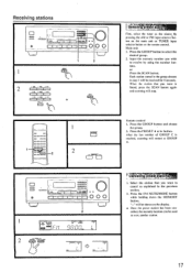
... previous section. 2. Select the station that you wish to store another station. 17 When the station that you want is reached, scanning will stop. Remote control 1. c> Val lieliliMetStatiO 1. Input the memory number you want to select the desired group. 2. Fig 0 0 1 1 O O O 2...number of GROUP C is found, press the SCAN button again and scanning will restart at GROUP A. 1=1 o • I will be shown on the remote control. Press the GROUP button to cancel as the source by using the number buttons. CAT .. Receiving stations I :11 .027.loCO2 .,..22.001.;...
... previous section. 2. Select the station that you wish to store another station. 17 When the station that you want is reached, scanning will stop. Remote control 1. c> Val lieliliMetStatiO 1. Input the memory number you want to select the desired group. 2. Fig 0 0 1 1 O O O 2...number of GROUP C is found, press the SCAN button again and scanning will restart at GROUP A. 1=1 o • I will be shown on the remote control. Press the GROUP button to cancel as the source by using the number buttons. CAT .. Receiving stations I :11 .027.loCO2 .,..22.001.;...
Owner Manual
Page 23
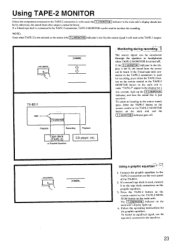
... the source signal is still sent to the source sound, press either the TAPE-2 button on the remote control or the TAPE-2 MONITOR button on the graphic equalizer. 3. TAPES MONITOR B TX-8511 AMP. T-2 MONITOR Playback Recording Playback Tape deck TAPE-2 or Graphic Equalizer CD player, etc. Monitoring ...unit to monitor the recording. Follow the operating instructions for recording, press either the TAPE-2 button on the remote control or the TAI'E-2 MONITOR button on the rear panel of the TX-8511. 2. IF a second tape deck is used , connect it to the TAPE-2 connectors on the main...
... the source signal is still sent to the source sound, press either the TAPE-2 button on the remote control or the TAPE-2 MONITOR button on the graphic equalizer. 3. TAPES MONITOR B TX-8511 AMP. T-2 MONITOR Playback Recording Playback Tape deck TAPE-2 or Graphic Equalizer CD player, etc. Monitoring ...unit to monitor the recording. Follow the operating instructions for recording, press either the TAPE-2 button on the remote control or the TAI'E-2 MONITOR button on the rear panel of the TX-8511. 2. IF a second tape deck is used , connect it to the TAPE-2 connectors on the main...
Owner Manual
Page 24
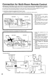
... connect it to U.S. Connect the sub room speaker cables to the TX-8511. 2. Components(d) TX-8511 I Speaker A (Main room) \ 7-\ \ TX-8511 7 , Speaker A (Main room) 3. Make the connections described above 4. Do not make a mistake when connecting the units. Onkyo components (a) I 1. A (Main room) Speaker A (Main room) Power supply' Remote control Remote Sensor Speaker B (Sub oom) Speaker B (Sub room) 1. Connect the components...
... connect it to U.S. Connect the sub room speaker cables to the TX-8511. 2. Components(d) TX-8511 I Speaker A (Main room) \ 7-\ \ TX-8511 7 , Speaker A (Main room) 3. Make the connections described above 4. Do not make a mistake when connecting the units. Onkyo components (a) I 1. A (Main room) Speaker A (Main room) Power supply' Remote control Remote Sensor Speaker B (Sub oom) Speaker B (Sub room) 1. Connect the components...
Owner Manual
Page 25
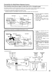
... Head 11E-10 so that its sensor is directed toward these components. I TX-8511 \ Spearke7 (Main room) 1/ . Install Remote Sensor Ilk -10 in the connection diagram below to the speaker B terminal on the TX-8511. (0)) 3. Components(b) Remote sensor Remote control- - Rnre,rmotseensor 10 2. Onkyo components (a) TX-8511 L Speaker A -',/ Speaker A (Main room) / f* (Main room) 7 -\ \`. Connect the sub room speaker cables to...
... Head 11E-10 so that its sensor is directed toward these components. I TX-8511 \ Spearke7 (Main room) 1/ . Install Remote Sensor Ilk -10 in the connection diagram below to the speaker B terminal on the TX-8511. (0)) 3. Components(b) Remote sensor Remote control- - Rnre,rmotseensor 10 2. Onkyo components (a) TX-8511 L Speaker A -',/ Speaker A (Main room) / f* (Main room) 7 -\ \`. Connect the sub room speaker cables to...
Owner Manual
Page 26
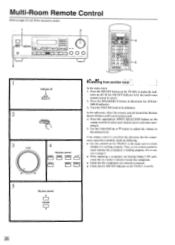
... to select your desired source and start operating it is not, refer to page 6. • When operating a component not bearing Onkyo's R I MU 4 :94 0 0 n o [n o n o n o- Multi-Room Remote Control Refer to pages 24 and 25 for connection details. 1 I 0 0 OO 00 I I rwm I I I 10 _ J 2 lot...room system cannot be controlled, check the following: • Use the controls On the TX-8511 in the main room to check whether it is not lit. 5 Remote control A VOLUME Mil V 26 t___ -i 3 VOLUME 0 .... ..... 4 Remote control TAPE-1 TUNER PHONO C 0 TAPE-2 VIDE0-1 VIDO t,rListe2CnTirn.
... to select your desired source and start operating it is not, refer to page 6. • When operating a component not bearing Onkyo's R I MU 4 :94 0 0 n o [n o n o n o- Multi-Room Remote Control Refer to pages 24 and 25 for connection details. 1 I 0 0 OO 00 I I rwm I I I 10 _ J 2 lot...room system cannot be controlled, check the following: • Use the controls On the TX-8511 in the main room to check whether it is not lit. 5 Remote control A VOLUME Mil V 26 t___ -i 3 VOLUME 0 .... ..... 4 Remote control TAPE-1 TUNER PHONO C 0 TAPE-2 VIDE0-1 VIDO t,rListe2CnTirn.
Owner Manual
Page 27
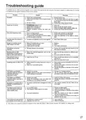
...cord. • Turn the power switch off, and then on AM (particularly conspicuous at night or with the remote control. • Check connection cables, speaker cables, etc. • Contact your Onkyo Service Center. • Switch off. • Switch off . • Noise from automobile ignition. •... farther apart. Troubleshooting guide If a problem occurs, while you are using the remote control, first operate the unit using, the front panel controls to confirm that it again. • Contact your Onkyo Service Center. Rough or scratchy sound; High range is not clear • ...
...cord. • Turn the power switch off, and then on AM (particularly conspicuous at night or with the remote control. • Check connection cables, speaker cables, etc. • Contact your Onkyo Service Center. • Switch off. • Switch off . • Noise from automobile ignition. •... farther apart. Troubleshooting guide If a problem occurs, while you are using the remote control, first operate the unit using, the front panel controls to confirm that it again. • Contact your Onkyo Service Center. Rough or scratchy sound; High range is not clear • ...

Owner Manual
Page 28
...2.8 A Other models: 220 W Dimensions (%V x H x D): W'ei!ht: 435 x 150 x 322 mm 17-1/8"x 5-7/8" x 12-11/16" 8.9 kg. 19.6 lbs REMOTE CONTROL RC-329S Transmitter: Infrared Signal range: Power supply: Approx. 5 meters. 16 ft. Two "AA" batteries (1.5 V x 2) Specifications and features are subject to 108.00 ... steps) 30µV 40 dB 40 dB 40 dB 0.7% GENERAL Power Supply: U.S. Kwai Chung. N.T., HONG KONG Tel: 852.2429-3118 Fax: 852-2428-9039 ONKYO httpiNJHewOMwE.ePnAkGyEoI.m.fp/ 107960 European models: 2 x 100 Watts at 4 ohms, I kHz (DLNI Asian models: 2 x 130 Watts at -I ohms, 1 kHz ...
...2.8 A Other models: 220 W Dimensions (%V x H x D): W'ei!ht: 435 x 150 x 322 mm 17-1/8"x 5-7/8" x 12-11/16" 8.9 kg. 19.6 lbs REMOTE CONTROL RC-329S Transmitter: Infrared Signal range: Power supply: Approx. 5 meters. 16 ft. Two "AA" batteries (1.5 V x 2) Specifications and features are subject to 108.00 ... steps) 30µV 40 dB 40 dB 40 dB 0.7% GENERAL Power Supply: U.S. Kwai Chung. N.T., HONG KONG Tel: 852.2429-3118 Fax: 852-2428-9039 ONKYO httpiNJHewOMwE.ePnAkGyEoI.m.fp/ 107960 European models: 2 x 100 Watts at 4 ohms, I kHz (DLNI Asian models: 2 x 130 Watts at -I ohms, 1 kHz ...


