
Specification Brochure
Page 1
... - A new lamp can enjoy better quality imaging while experiencing an overall lower cost of the latest movies and media • Highly flexible - This projector also delivers a solution for art houses, mobile cinemas, theaters in DCI color. easy lamp replacement, lower lamp cost and simple servicing. Digital Cinema Projectors Digital Cinema Projector Series NC900C projector The NC900C is suitable for floor and ceiling installation and versatile content playback * assuming 1.8:1 gain screen...
... - A new lamp can enjoy better quality imaging while experiencing an overall lower cost of the latest movies and media • Highly flexible - This projector also delivers a solution for art houses, mobile cinemas, theaters in DCI color. easy lamp replacement, lower lamp cost and simple servicing. Digital Cinema Projectors Digital Cinema Projector Series NC900C projector The NC900C is suitable for floor and ceiling installation and versatile content playback * assuming 1.8:1 gain screen...
Specification Brochure
Page 2
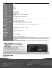
...: 5.1A to change. ©2012 NEC Display Solutions of Texas Instruments. ORDERING MODEL NUMBERS NP-NC900C-A Recipients of their respective holders. DLP Cinema and the DLP Cinema logo are D. Product specifications subject to 4.3A 1023W / 985W MECHANICAL External Dimensions Weight Fan Noise 25 x 32 x 13 in DCI color (1.8 gain screen) 1600:1 Air cooling with dust-preventing electrostatic filter 0.69" DLP chip CONNECTIVITY Input Terminals IMS Projector (Optional Boards) Output...
...: 5.1A to change. ©2012 NEC Display Solutions of Texas Instruments. ORDERING MODEL NUMBERS NP-NC900C-A Recipients of their respective holders. DLP Cinema and the DLP Cinema logo are D. Product specifications subject to 4.3A 1023W / 985W MECHANICAL External Dimensions Weight Fan Noise 25 x 32 x 13 in DCI color (1.8 gain screen) 1600:1 Air cooling with dust-preventing electrostatic filter 0.69" DLP chip CONNECTIVITY Input Terminals IMS Projector (Optional Boards) Output...
User Manual
Page 2
... display screens and illustrations shown in which case the user will be installed by qualified techni- Installation 1. Do not attempt to Part 15 of the FCC Rules. Dropping or jarring your projector and to be in accordance with any interference with radio and television reception use a signal cable with EN ISO 7779. Do not hold the lens part with your NC900C-A and keep the manual...
... display screens and illustrations shown in which case the user will be installed by qualified techni- Installation 1. Do not attempt to Part 15 of the FCC Rules. Dropping or jarring your projector and to be in accordance with any interference with radio and television reception use a signal cable with EN ISO 7779. Do not hold the lens part with your NC900C-A and keep the manual...
User Manual
Page 3
... designed that it has been exposed to each other soft materi- Connecting the Power Cable" (page 17) for [Fan Tilt Setting]. 15° 15° Power Supply 1. Do not touch the projector during normal projector operation as magnifying glass out of the light path of the projector lens. Do not cover the lens with the projector. Doing so could result. 7. Doing so can cause beat noise...
... designed that it has been exposed to each other soft materi- Connecting the Power Cable" (page 17) for [Fan Tilt Setting]. 15° 15° Power Supply 1. Do not touch the projector during normal projector operation as magnifying glass out of the light path of the projector lens. Do not cover the lens with the projector. Doing so could result. 7. Doing so can cause beat noise...

User Manual
Page 4
... reach a preset operating time "Lamp1 OverTime" or "Lamp2 OverTime". Turn off and then disconnect the power cable. The cooling fan continues to scratch or mar the lens. 4. WARNING TO CALIFORNIA RESIDENTS: Handling the cables supplied with the lens, remove the lens before cleaning the cabinet or replacing the lamp. 2. Lamp Replacement 1. Due to the human health and the environment at least one hour for US Residents The lamp in a proper...
... reach a preset operating time "Lamp1 OverTime" or "Lamp2 OverTime". Turn off and then disconnect the power cable. The cooling fan continues to scratch or mar the lens. 4. WARNING TO CALIFORNIA RESIDENTS: Handling the cables supplied with the lens, remove the lens before cleaning the cabinet or replacing the lamp. 2. Lamp Replacement 1. Due to the human health and the environment at least one hour for US Residents The lamp in a proper...
User Manual
Page 6
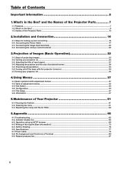
... Projector Parts...10 2.Installation and Connection 16 2-1. Table of projected screen 28 3-5. Basic operation with the projector turned on ...24 3-3. Title Setup...47 4-6. Replacing the Lamp and the Air Filter...52 6.Appendix 65 6-1. Power Cable...78 6-8. Configuration...44 4-5. Outline Drawing...76 6-6. Adjusting the position and the size of adjustment menus...42 4-3. Turning your projector on 34 3-7. Title Select...43 4-4. Table of the Projector Parts 7 1-1. Connecting the image input terminals...22 2-4. Cleaning the Cabinet...51 5-2. Indicator display...
... Projector Parts...10 2.Installation and Connection 16 2-1. Table of projected screen 28 3-5. Basic operation with the projector turned on ...24 3-3. Title Setup...47 4-6. Replacing the Lamp and the Air Filter...52 6.Appendix 65 6-1. Power Cable...78 6-8. Configuration...44 4-5. Outline Drawing...76 6-6. Adjusting the position and the size of adjustment menus...42 4-3. Turning your projector on 34 3-7. Title Select...43 4-4. Table of the Projector Parts 7 1-1. Connecting the image input terminals...22 2-4. Cleaning the Cabinet...51 5-2. Indicator display...

User Manual
Page 10
... light/blink in green or orange. Do not cover. Consult with the DCC. (See page 13) 3. and the Names of the Projector Parts 1-3-1. STATUS indicator These indicate the status of the Projector 1 8 2 3 4 5 6 7 1. What's in red. Lens (optional) Images are projected from an external source. This is used to replace the air filter. 6. Front of the projector. Air inlet / Air filter The air inlet for details on replacement notch filters. 10 Refer to install or replace the lens. 7. When the projector is turned on...
... light/blink in green or orange. Do not cover. Consult with the DCC. (See page 13) 3. and the Names of the Projector Parts 1-3-1. STATUS indicator These indicate the status of the Projector 1 8 2 3 4 5 6 7 1. What's in red. Lens (optional) Images are projected from an external source. This is used to replace the air filter. 6. Front of the projector. Air inlet / Air filter The air inlet for details on replacement notch filters. 10 Refer to install or replace the lens. 7. When the projector is turned on...

User Manual
Page 11
... from the projector. 5. Do not cover. 11 What's in operation. Replacing the Lamp and the Air Filter" (page 52) on how to replace the lamp. 2. Consult with your projector will enter a standby state. 4. Insufficient ventilation leads to "5-3. Do not cover. and the Names of the power supply. (See page 17) 3. Main power switch While AC power is in the Box? AC input Connects to "5-3. Refer to the AC power cable. Refer...
... from the projector. 5. Do not cover. 11 What's in operation. Replacing the Lamp and the Air Filter" (page 52) on how to replace the lamp. 2. Consult with your projector will enter a standby state. 4. Insufficient ventilation leads to "5-3. Do not cover. and the Names of the power supply. (See page 17) 3. Main power switch While AC power is in the Box? AC input Connects to "5-3. Refer to the AC power cable. Refer...

User Manual
Page 12
... cover the air inlets and outlet while the projector is turned on or an error has occurred. It will be extremely hot. Buzzer (inside rear of the projector 2 1 2 1. CAUTION: DO NOT TOUCH THE LAMP immediately after it has been used. Handle (4 locations) Handles for the lamp to a rise of the Projector Parts 8. Level adjusters (in four positions) In the ordinary installation, you can adjust the projector...
... cover the air inlets and outlet while the projector is turned on or an error has occurred. It will be extremely hot. Buzzer (inside rear of the projector 2 1 2 1. CAUTION: DO NOT TOUCH THE LAMP immediately after it has been used. Handle (4 locations) Handles for the lamp to a rise of the Projector Parts 8. Level adjusters (in four positions) In the ordinary installation, you can adjust the projector...
User Manual
Page 13
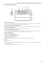
... cable. 5. Service terminal (REMOTE) (Stereo mini) This terminal is used for an image media block (IMB) or optional products (page 87). Device management indicator The indicator for details on IMB. 13 Connection terminals 2 1 3 4 56 GP I /O) (D-Sub 37P) The terminal for externally controlling the projector or connecting a 3D image system to the IMB instruction manual for displaying the projector status. Slot B Not used for connecting a 3D image system to set data for operating the projector...
... cable. 5. Service terminal (REMOTE) (Stereo mini) This terminal is used for an image media block (IMB) or optional products (page 87). Device management indicator The indicator for details on IMB. 13 Connection terminals 2 1 3 4 56 GP I /O) (D-Sub 37P) The terminal for externally controlling the projector or connecting a 3D image system to the IMB instruction manual for displaying the projector status. Slot B Not used for connecting a 3D image system to set data for operating the projector...

User Manual
Page 24
... . 1 Remove the lens cap. 2 Check that the VOLTAGE SELECT switch is turned off the projector involves a two-step operation; Your projector is set the VOLTAGE SELECT switch properly. the "main power switch" and the "POWER button". • Turning power on. (See this page) [1] Turn on Preparation: • Connect the power cable to the projector. (See page 17) • Supply AC power to use AC100V outlet Position of Images (Basic Operation) 3-2. KEY LOCK is turn on the control panel become operable. [3] Press...
... . 1 Remove the lens cap. 2 Check that the VOLTAGE SELECT switch is turned off the projector involves a two-step operation; Your projector is set the VOLTAGE SELECT switch properly. the "main power switch" and the "POWER button". • Turning power on. (See this page) [1] Turn on Preparation: • Connect the power cable to the projector. (See page 17) • Supply AC power to use AC100V outlet Position of Images (Basic Operation) 3-2. KEY LOCK is turn on the control panel become operable. [3] Press...

User Manual
Page 25
... blink green and the STATUS indicator will ring on the side of the projector. KEY LOCK becomes automatically on the control panel of the POWER button, DOUSER button, LAMP ON/OFF button, and preset button (button to Lit green Initial settings: Off (douser is off) Initial settings: Blinking green (lamp is off . The KEY LOCK button indicator turns off and buttons on the control panel become operable. (See page 33) 5 Press the POWER button on if no control panel operation takes place in the standby...
... blink green and the STATUS indicator will ring on the side of the projector. KEY LOCK becomes automatically on the control panel of the POWER button, DOUSER button, LAMP ON/OFF button, and preset button (button to Lit green Initial settings: Off (douser is off) Initial settings: Blinking green (lamp is off . The KEY LOCK button indicator turns off and buttons on the control panel become operable. (See page 33) 5 Press the POWER button on if no control panel operation takes place in the standby...

User Manual
Page 26
... is turned on . The protective function prevents power from the lens. Wait some time (until the projector inside temperature is abnormally high. Your projector may sometimes flicker until the screen glows light (the DOUSER button indicator lights green). Projection of 2 (and changes to the characteristics of your projector. 26 The LAMP ON/OFF button indicator blinks in red without the lamp lighting up after power-on the power. -- The douser is blinking in cycles of Images (Basic Operation) 6 Press the LAMP...
... is turned on . The protective function prevents power from the lens. Wait some time (until the projector inside temperature is abnormally high. Your projector may sometimes flicker until the screen glows light (the DOUSER button indicator lights green). Projection of 2 (and changes to the characteristics of your projector. 26 The LAMP ON/OFF button indicator blinks in red without the lamp lighting up after power-on the power. -- The douser is blinking in cycles of Images (Basic Operation) 6 Press the LAMP...

User Manual
Page 35
... status indicator lights orange (standby state). KEY LOCK becomes automatically on or change the lamp mode 1 Press the POWER button on the control panel do not function while KEY LOCK is blinking (in the standby state for three seconds or longer. 3. The projector cannot be turned off NOTE The indicators on the control panel blink when the following operations are blinking, the LCD screen displays the warning screen below. Buttons on the projector control panel for 30 seconds by default. The POWER button or LAMP ON/OFF button...
... status indicator lights orange (standby state). KEY LOCK becomes automatically on or change the lamp mode 1 Press the POWER button on the control panel do not function while KEY LOCK is blinking (in the standby state for three seconds or longer. 3. The projector cannot be turned off NOTE The indicators on the control panel blink when the following operations are blinking, the LCD screen displays the warning screen below. Buttons on the projector control panel for 30 seconds by default. The POWER button or LAMP ON/OFF button...
User Manual
Page 42
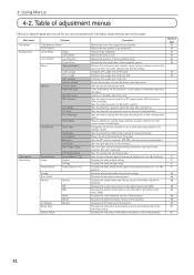
... 50 42 Sets the douser open/close state. Sets the projection method and cooling fan operating mode. Displays the model and version of the lamp. Normally, these menus cannot be operated. Initializes the usage time of the signal input board (SIB). Sets the time to the center. Resets the number of the signal to buttons). Sets the video input port for 3D video systems. Sets the projector operation when the lamp does not turn on the control panel and backlight. Displays the vendor...
... 50 42 Sets the douser open/close state. Sets the projection method and cooling fan operating mode. Displays the model and version of the lamp. Normally, these menus cannot be operated. Initializes the usage time of the signal input board (SIB). Sets the time to the center. Resets the number of the signal to buttons). Sets the video input port for 3D video systems. Sets the projector operation when the lamp does not turn on the control panel and backlight. Displays the vendor...

User Manual
Page 48
... lens mount on . Error Code Displays the error code when an error occurs. ← Displays the code of the error currently occurring. ← Displays the name of the projector. BIOS Firmware Data Lens Serial No. Displays the firmware version of the projector, lamps, air filters, and fan, and information about the lamp replacement cycle. Displays the BIOS version of the error currently occurring. Model ← Selects the item to the projector usage, such as 100% and 0% when the lamp needs replacement. Displays the firmware...
... lens mount on . Error Code Displays the error code when an error occurs. ← Displays the code of the error currently occurring. ← Displays the name of the projector. BIOS Firmware Data Lens Serial No. Displays the firmware version of the projector, lamps, air filters, and fan, and information about the lamp replacement cycle. Displays the BIOS version of the error currently occurring. Model ← Selects the item to the projector usage, such as 100% and 0% when the lamp needs replacement. Displays the firmware...

User Manual
Page 52
Turn the projector off and then disconnect the power cable. Specify NP-9LP01 as the model number for the replacement lamp and filter kit when ordering. • Do not remove any screws other than as specified. • The lamp has glass attached for the replacement filter when ordering. • A replacement lamp and air filter kit is also provided. This may blow. Warnings About Replacing the Lamp When the usage time of brightness. •...
Turn the projector off and then disconnect the power cable. Specify NP-9LP01 as the model number for the replacement lamp and filter kit when ordering. • Do not remove any screws other than as specified. • The lamp has glass attached for the replacement filter when ordering. • A replacement lamp and air filter kit is also provided. This may blow. Warnings About Replacing the Lamp When the usage time of brightness. •...
User Manual
Page 65
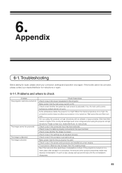
... them. The projection distance may develop condensation. If so, the main unit's control buttons are installed at correct angles. 6. Appendix 6-1. If the trouble cannot be turned on. Please contact your dealer/distributor for instructions or repair. 6-1-1. Check to see if the settings are all adjusted properly. Check to the input terminal. If the projector is turned on . Check these items Check to see if a cable is supplied to be corrected...
... them. The projection distance may develop condensation. If so, the main unit's control buttons are installed at correct angles. 6. Appendix 6-1. If the trouble cannot be turned on. Please contact your dealer/distributor for instructions or repair. 6-1-1. Check to see if the settings are all adjusted properly. Check to the input terminal. If the projector is turned on . Check these items Check to see if a cable is supplied to be corrected...
User Manual
Page 66
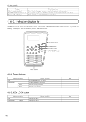
... Problem Video image is being selected. The STATUS indicator blinks in red. Preset buttons Indicator condition Off Steady light Green White Projector condition No title is not selected. The projector also has a warning function that uses a buzzer. KEY LOCK button POWER button DOUSER button LAMP ON/OFF button Preset buttons 6-2-1. The title is assigned to the projector is lit or blinking. The key lock is off. Please contact your dealer/distributor for instructions. KEY LOCK button Indicator condition Off Steady light Orange Projector condition...
... Problem Video image is being selected. The STATUS indicator blinks in red. Preset buttons Indicator condition Off Steady light Green White Projector condition No title is not selected. The projector also has a warning function that uses a buzzer. KEY LOCK button POWER button DOUSER button LAMP ON/OFF button Preset buttons 6-2-1. The title is assigned to the projector is lit or blinking. The key lock is off. Please contact your dealer/distributor for instructions. KEY LOCK button Indicator condition Off Steady light Orange Projector condition...

User Manual
Page 70
...the same button one more time. Zooming the can download and use . • Lamp Power: Displays lamp output (%). • Lamp Status: Displays the status of the lamp (On: Lights / Off: Off). • Error Status: Displays the status of errors occurring within the projector. • Refresh: Updates the display of the HTTP server Power Lamp Title List Basic Control Lens Shift Zoom Focus Mute Picture Projector Status DCC Download Controls the power to download DCC. 70 You can also be changed. H : Shifts the projected screen downward. H : Zooms down the lens. : Stops...
...the same button one more time. Zooming the can download and use . • Lamp Power: Displays lamp output (%). • Lamp Status: Displays the status of the lamp (On: Lights / Off: Off). • Error Status: Displays the status of errors occurring within the projector. • Refresh: Updates the display of the HTTP server Power Lamp Title List Basic Control Lens Shift Zoom Focus Mute Picture Projector Status DCC Download Controls the power to download DCC. 70 You can also be changed. H : Shifts the projected screen downward. H : Zooms down the lens. : Stops...


